EP4520626A1 - Conteneur roulant - Google Patents
Conteneur roulant Download PDFInfo
- Publication number
- EP4520626A1 EP4520626A1 EP23195863.8A EP23195863A EP4520626A1 EP 4520626 A1 EP4520626 A1 EP 4520626A1 EP 23195863 A EP23195863 A EP 23195863A EP 4520626 A1 EP4520626 A1 EP 4520626A1
- Authority
- EP
- European Patent Office
- Prior art keywords
- base
- side walls
- roll container
- container according
- roll
- Prior art date
- Legal status (The legal status is an assumption and is not a legal conclusion. Google has not performed a legal analysis and makes no representation as to the accuracy of the status listed.)
- Pending
Links
Images


Classifications
-
- B—PERFORMING OPERATIONS; TRANSPORTING
- B62—LAND VEHICLES FOR TRAVELLING OTHERWISE THAN ON RAILS
- B62B—HAND-PROPELLED VEHICLES, e.g. HAND CARTS OR PERAMBULATORS; SLEDGES
- B62B3/00—Hand carts having more than one axis carrying transport wheels; Steering devices therefor; Equipment therefor
- B62B3/002—Hand carts having more than one axis carrying transport wheels; Steering devices therefor; Equipment therefor characterised by a rectangular shape, involving sidewalls or racks
-
- B—PERFORMING OPERATIONS; TRANSPORTING
- B62—LAND VEHICLES FOR TRAVELLING OTHERWISE THAN ON RAILS
- B62B—HAND-PROPELLED VEHICLES, e.g. HAND CARTS OR PERAMBULATORS; SLEDGES
- B62B2205/00—Hand-propelled vehicles or sledges being foldable or dismountable when not in use
- B62B2205/006—Hand-propelled vehicles or sledges being foldable or dismountable when not in use dismountable
-
- B—PERFORMING OPERATIONS; TRANSPORTING
- B62—LAND VEHICLES FOR TRAVELLING OTHERWISE THAN ON RAILS
- B62B—HAND-PROPELLED VEHICLES, e.g. HAND CARTS OR PERAMBULATORS; SLEDGES
- B62B2205/00—Hand-propelled vehicles or sledges being foldable or dismountable when not in use
- B62B2205/20—Catches; Locking or releasing an articulation
Definitions
- the invention relates to a roll container, in particular a roll container, with a base mounted on rollers, and with a grid wall frame arranged on the base in the transport position and detachably connected to the base, comprising at least two opposite side walls, wherein the respective side wall is detachably connected to the base by means of at least one foot-side, rotatably hinged locking element.
- Roll containers are often used in practice to transport items such as food.
- the food is packaged in small containers, ensuring smooth transport. This applies both within logistics centers and, from there, in connection with the loading of trucks, and ultimately for distribution at individual supermarkets and within them.
- the individual roll containers can be easily rolled back and forth by the operating personnel.
- two fixed casters and two rotating casters are usually used on the base.
- four rotating casters on the base can also be used.
- Such roll containers have proven their worth because they facilitate transport and thus the handling of goods. Furthermore, such roll containers are inexpensive, generally easy to clean, and are suitable for a closed-loop system, meaning that the unloaded roll containers can be transported, for example, from the retail store back to the logistics center. Various approaches are being pursued in practice.
- roll containers are often nested upside down for empty transport. This allows two roll containers to be stacked so that they only take up the space of one roll container.
- the teaching of the EP 3 015 340 B1 A locking mechanism is provided which, in an open position, allows the side wall to be inserted into a recess in the base. In a closed position, the side wall, which is inserted into the recess along a path of movement, can be anchored relative to the base.
- the locking mechanism is a rotary latch that can be rotated about an axis of rotation. The locking mechanism can be moved between the open and closed positions by rotating the rotary latch about the axis of rotation. The weight of the side wall locks the rotary latch.
- the rotary latch or locking mechanism is rotatably connected to the base.
- such generic roll containers which have been in widespread use for a long time, are characterized by DE 29 37 420 A1 It is characterized by a simple locking mechanism, often referred to as a drop bar.
- a simple locking mechanism often referred to as a drop bar.
- the locking element engages automatically or when the operator applies pressure (with their foot), and the release can also be initiated by the operator using their foot.
- the locking element is DE 29 37 420 A1 around a clamp or bracket that is pivoted around a horizontal axis on the side wall. The end of the bracket is bent so that it grips underneath the base in the transport position.
- the locking element is a component of the side wall.
- the locking element is designed as part of the base.
- the transport position corresponds to the fact that the opposing side walls defining the grid wall frame are connected to the base and stand on the base (vertically and at the edges). In this way, the interior of the grid wall frame or between the The space available on the opposite side walls can be used for the objects described above, in particular food containers for transport.
- the so-called and in the generic state of the art according to the DE 29 37 420 A1 The storage position discussed means that the roll container is stored empty and/or transported back for refilling.
- the invention is based on the technical problem of further developing such a roll container such that its volume, particularly in the storage position, is reduced compared to previous approaches. Furthermore, a corresponding combination of the roll container in question in its transport position and at least one other roll container in the corresponding storage position is to be provided.
- a generic (and in transport position) roll container and in particular a roll container within the scope of the invention is characterized in that the base is provided with at least one recess for receiving the respective locking element one or more side walls placed inside the grid wall frame and on the base in their storage position.
- the invention therefore initially relies on a specially designed base, which is equipped with at least one recess, usually in the center.
- a recess can be easily incorporated into the base, because the base is generally a plastic injection-molded part.
- the recess therefore only requires a corresponding adjustment of the injection mold.
- An additional rotatable mounting of the locking element, as in the EP 3 015 340 B1 is unnecessary because, according to the invention, the locking element is rotatably mounted on the side wall. This is usually done in such a way that the recess in the base is designed as a rectangular recess.
- the rectangular recess in question usually runs transversely to the longitudinal extension of the side walls connected to the base and standing perpendicularly thereto in the transport position of the roll container.
- This recess accommodates at least one side wall placed on the base in the storage position.
- the side wall is housed inside the mesh wall frame, i.e., in the storage position in question, it is located between the two side walls defining the mesh wall frame and connected to the base.
- the side walls placed on the base and inside the mesh wall frame in the storage position are those resulting from other roll containers that have been disassembled for this purpose and are now in their storage position.
- the roll container according to the invention in its transport position, at least two additional, usually three additional and mostly even four additional disassembled roll containers are transported inside the grid wall frame and on the base in their storage position.
- the storage position corresponds to the roll container intended for transport assuming its transport position, i.e. the side walls defining the grid wall frame are connected to the base and rest vertically and on its edges.
- the additional roll containers transported with the aid of the roll container in the transport position assume their storage position, i.e. are disassembled. Disassembly takes place in such a way that the side walls are detached from the base using the locking element. Consequently, the side walls and the base are available as individual components and can then be transported in an empty state using the roll container in the transport position.
- a further advantage is that no specially designed locking elements are required as is the case with the EP 3 015 340 B1 on the base are required, and accordingly, the recesses in the base that are obligatory in this context and accommodate the side walls can be omitted. Rather, the side walls of the rolling container according to the invention are placed on the flat floor or base, respectively, and complicated locking mechanisms are expressly not required.
- the invention operates with the simply constructed locking element that is simply rotatably mounted on the base.
- the locking element is generally pivotally connected to a lower crossbar of the side wall.
- the locking element therefore represents a mostly captive component of the side wall.
- the locking element is usually designed as a tab with an articulated eye.
- the design is such that the locking element at least partially engages underneath the base when the roll container is in the transport position. This fixes the side wall relative to the base on the one hand and ensures that the side wall rests vertically and on the edges of the base on the other. This is further enhanced by the fact that the side wall in question, with its respective corner posts, is accommodated in the receptacles and, in particular, plug-in receptacles of the base.
- the plug-in receptacles are usually provided in the respective corners of the base.
- the locking element can additionally be equipped with an actuating arm. Furthermore, the locking element can be designed and function as described in the generic state of the art according to DE 29 37 420 A1 This means that the roll container according to the invention can be combined with side walls that have been on the market for a long time. Since the side walls are connected to the base are equipped with rotatably hinged locking elements and otherwise have no other special locking features, roll containers already on the market can also be transferred to their storage position in this way and then stored and transported with the roll container according to the invention in its transport position.
- the base is usually equipped with one or more receptacles or plug-in receptacles for holding the side panels placed on the base. This means that the side panels placed on the base for transport can be inserted onto or into the base. Additional locking using the locking elements is not provided in the storage position, as the locking elements hang from the side panel and insert into the recess.
- the side walls can just as easily be placed on the base not with their corner posts facing forward, but rather with their heads facing forward in an inverted configuration. Secure the side walls placed on the base in this way by one or more clamping devices connected to at least one side wall, which close one or both openings between the opposing side walls.
- several bases of the roll containers can also be accommodated inside the mesh wall frame and on the base.
- the procedure is further such that one or more receptacles are provided in the base opposite one another and function as plug-in receptacles for the corner posts of the side walls.
- the procedure is usually such that receptacles are provided in the center of the base for the adjacent plug-in receptacle of two side walls in their storage position. Additional side walls and/or bases of the disassembled roll containers can now be placed on either side of the side walls provided in the center of the base in this way.
- the one or more clamping devices ensure that the disassembled roll containers are received and held inside the mesh wall frame.
- the invention also relates to a combination of the previously described roll container and at least one side wall placed in storage position inside the mesh wall frame and on the base.
- the mesh wall frame usually accommodates a total of eight side walls of four disassembled roll containers inside and on the base, usually in conjunction with the corresponding four bases of the respective disassembled roll containers.
- Roll container This explains why the roll container according to the invention is capable of accommodating four disassembled roll containers within its interior, so that the space of one roll container is occupied by a total of five roll containers, namely four in their storage position and one in the transport position.
- Starting from at least one side wall preferably inserted centrally into the base, side walls placed on both sides of the base and, if necessary, bases can be provided inside the grid wall frame and transported in this way.
- two adjacent side walls are provided in the center of the base, from which the side walls placed on the base and, if necessary, bases are placed inside the grid wall frame on both sides.
- the side walls placed on the base are aligned parallel to the side walls defining the grid wall frame.
- the multiple bases of the disassembled roll containers placed on the base are aligned parallel to the side walls defining the grid wall frame.
- the multiple bases of the disassembled roll containers placed on the base are aligned parallel to the side walls defining the grid wall frame.
- the multiple bases of the disassembled roll containers placed on the base are aligned parallel to the side walls defining the grid wall frame.
- the multiple bases of the disassembled roll containers placed on the base In this way, a particularly high packing density is achieved inside the grid wall frame and, as a maximum, the four roll containers disassembled in their storage position can generally be accommodated and stored inside the grid wall frame and on the base of the roll container according to the invention in its transport position and/or transported back empty, for example, to a logistics center.
- a further advantage is that the roll containers disassembled in their storage position have a largely even weight distribution inside the roll container in the transport position. This means that the roll container
- a grid wall frame 3 is arranged on the base 2 and is detachably connected to the base 2.
- the grid wall frame 3 is composed of at least two opposing side walls 3.
- the side walls or the grid wall frame 3 are detachably connected to the base 2 and, in the manner realized in this way and in the Fig. 1 In the transport position shown, it is positioned vertically on the base 2 and on the edges. In the storage position of the roll container, the side walls 3 are detached from the base 2 and the roll container is disassembled accordingly.
- a recess 6 is provided in the base 2 which connects the respective plug-in receptacles 5 to one another and is curved in cross-section, in which the lower crossbar 3a with the locking element 4 pivotally connected thereto is arranged in the transport position as shown in the Fig. 1
- An additional recess 7 ensures that the locking element 4 in the transport position according to the embodiment is Fig. 1 can releasably engage underneath the base 2. This releasably locks the side wall 3 relative to the base 2 in the transport position.
- the locking element 4 is the already mentioned tab with the hinge eyelet.
- the tab according to the exemplary embodiment is essentially and in side view predominantly rectangular in shape with a largely vertically extending leg 4a, which runs along the edge of the base 2, and a predominantly horizontally aligned leg 4b, which engages under the base 2.
- the locking element 4 according to the exemplary embodiment is also equipped with an actuating arm 4c. Via the actuating arm 4c, the locking element 4 can be moved from its in the side view after the Fig. 2 shown locked state.
- the base 2 in conjunction with the recess 8 serves to receive the respective locking element 4 of one or more side walls 3 placed inside the grid wall frame 3 and on the base 2 in storage position.
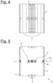
- This can best be seen from the perspective view in the Fig. 1 compared to the supervision on the basis 2 after the Fig. 5
- a transport space or transport volume is provided, which in the Fig. 1 illustrated transport position of the roll container according to the invention is used and intended for receiving, for example, foodstuffs in the form of containers.
- the base 2 additionally has one or more receptacles 9, which serve to plug in the side walls 3 placed on the base 2.
- the respective corner posts 3c of the side walls 3 of the disassembled roll containers can be inserted into the respective and opposite receptacles 9. This is, of course, not mandatory, because the side walls 3 accommodated inside the mesh wall frame 3 can also be placed upside down on the base 2 with their head-end or upper crossbar 3b.
- the receptacles 9 on the base 2 for the side walls 3, which are here transported in a picked-up and disassembled state, are provided opposite one another on the base 2 and are designed as respective plug-in receptacles for the corner posts 3c of the side walls 3.
- the design is usually such that plug-in receptacles or receptacles 9 are provided in the center of the base 2, specifically for the adjacent plug-in receptacle of two side walls 3 in their storage position. This can be seen from the two central and directly adjacent plug-in receptacles 9 of the four plug-in receptacles 9 in the Fig. 5 . This applies This is, of course, only an example and is by no means mandatory.
- the side walls 3 accommodated in the receptacles 9 remain in their storage position unchanged, because the associated locking elements 4 are inserted into the recess 8 and cannot provide additional fixation to the base 2.
- a recess 8 for the locking elements 4 placed in the middle of the side wall 3 in the Fig. 5 is provided.
- the base 2 has a corresponding number of recesses 8, although this is not shown.
- the roll container shown can be combined with at least one side wall 3 placed in storage position inside the grid wall frame 3 and on the base 2.
- the base 2 is used as shown in the Fig. 1
- a total of eight side walls 3 are accommodated, which, starting from the two central side walls 3, are alternately inserted with their corner posts 3c into the corresponding receptacles 9 or plug-in receptacles of the base 2 or, conversely, rest with their head-side crossbar 3b on the base 2.
- the packing volume of the roll containers according to the invention in disassembled state or in their storage position is significantly reduced compared to the prior art.
- roll containers equipped with conventional locking elements 4 as shown can also be picked up and transported in this way. This is because the locking elements 4 are accommodated in the recess or rectangular recess 8 in the center of the base 2 and are located there (see FIG. Fig. 5 ).
- one or more indicated clamping devices 10 can additionally be connected to the relevant side wall 3.
- the clamping devices 10 can be rubber bands, plastic straps, or combinations thereof.
Landscapes
- Engineering & Computer Science (AREA)
- Chemical & Material Sciences (AREA)
- Combustion & Propulsion (AREA)
- Transportation (AREA)
- Mechanical Engineering (AREA)
- Details Of Rigid Or Semi-Rigid Containers (AREA)
Priority Applications (1)
| Application Number | Priority Date | Filing Date | Title |
|---|---|---|---|
| EP23195863.8A EP4520626A1 (fr) | 2023-09-07 | 2023-09-07 | Conteneur roulant |
Applications Claiming Priority (1)
| Application Number | Priority Date | Filing Date | Title |
|---|---|---|---|
| EP23195863.8A EP4520626A1 (fr) | 2023-09-07 | 2023-09-07 | Conteneur roulant |
Publications (1)
| Publication Number | Publication Date |
|---|---|
| EP4520626A1 true EP4520626A1 (fr) | 2025-03-12 |
Family
ID=87971857
Family Applications (1)
| Application Number | Title | Priority Date | Filing Date |
|---|---|---|---|
| EP23195863.8A Pending EP4520626A1 (fr) | 2023-09-07 | 2023-09-07 | Conteneur roulant |
Country Status (1)
| Country | Link |
|---|---|
| EP (1) | EP4520626A1 (fr) |
Citations (8)
| Publication number | Priority date | Publication date | Assignee | Title |
|---|---|---|---|---|
| GB1231841A (fr) * | 1968-01-15 | 1971-05-12 | ||
| GB1253029A (fr) * | 1967-11-09 | 1971-11-10 | ||
| US3628805A (en) * | 1969-04-30 | 1971-12-21 | Peugeot Cycles | Handling truck |
| DE2937420A1 (de) | 1978-10-20 | 1980-04-30 | Reunis Sa Ateliers | Wand fuer einen transportkarren |
| DE2937421A1 (de) | 1979-09-15 | 1981-04-09 | Basf Ag, 6700 Ludwigshafen | Verfahren zur herstellung von 4-amino-5-chlor-1-phenylpyridazon-(6) |
| DE102007033147A1 (de) * | 2007-07-13 | 2009-01-22 | Gebhardt Transport- Und Lagersysteme Gmbh | Stapelbarer Rollbehälter |
| EP3015349A1 (fr) | 2014-10-31 | 2016-05-04 | Yamaha Hatsudoki Kabushiki Kaisha | Véhicule |
| EP3015340B1 (fr) | 2014-10-31 | 2017-08-30 | WALTHER Faltsysteme GmbH | Conteneur roulant dote de paroi laterale amovible |
-
2023
- 2023-09-07 EP EP23195863.8A patent/EP4520626A1/fr active Pending
Patent Citations (8)
| Publication number | Priority date | Publication date | Assignee | Title |
|---|---|---|---|---|
| GB1253029A (fr) * | 1967-11-09 | 1971-11-10 | ||
| GB1231841A (fr) * | 1968-01-15 | 1971-05-12 | ||
| US3628805A (en) * | 1969-04-30 | 1971-12-21 | Peugeot Cycles | Handling truck |
| DE2937420A1 (de) | 1978-10-20 | 1980-04-30 | Reunis Sa Ateliers | Wand fuer einen transportkarren |
| DE2937421A1 (de) | 1979-09-15 | 1981-04-09 | Basf Ag, 6700 Ludwigshafen | Verfahren zur herstellung von 4-amino-5-chlor-1-phenylpyridazon-(6) |
| DE102007033147A1 (de) * | 2007-07-13 | 2009-01-22 | Gebhardt Transport- Und Lagersysteme Gmbh | Stapelbarer Rollbehälter |
| EP3015349A1 (fr) | 2014-10-31 | 2016-05-04 | Yamaha Hatsudoki Kabushiki Kaisha | Véhicule |
| EP3015340B1 (fr) | 2014-10-31 | 2017-08-30 | WALTHER Faltsysteme GmbH | Conteneur roulant dote de paroi laterale amovible |
Similar Documents
| Publication | Publication Date | Title |
|---|---|---|
| EP0612301B1 (fr) | Dispositif de transport et/ou de stockage de marchandises de detail | |
| DE69702821T2 (de) | Zusammenlegbarer Container für Flugzeuge | |
| EP0464700B1 (fr) | Rail de stockage | |
| DE60212268T2 (de) | Schrank zum Befördern von Medizin | |
| DE3344659C1 (de) | Transportgestell fuer Haengefoerderung | |
| DE2155662A1 (de) | Anordnung zum Lagern, Transportieren und Abgeben strömungsfähiger Stoffe | |
| DD202520A5 (de) | Container | |
| DE202010017755U1 (de) | Gitterbox zur Handhabung und Lagerung von Gütern | |
| DE4217329A1 (de) | Siloeinheit | |
| DE102019111950B4 (de) | Stapelbare Lagereinheit und Stapel aus Lagereinheiten | |
| DE2333453A1 (de) | Von hand bewegbarer warenbehaelter | |
| EP4520626A1 (fr) | Conteneur roulant | |
| EP1008535A2 (fr) | Conteneur repliable | |
| DE202005012289U1 (de) | Zusammenlegbarer Behälter | |
| DE1805508A1 (de) | Behaelter fuer den Transport von Waren oder sogenannter Container | |
| DE69415061T2 (de) | Speditions-Behälter für verschiedene Güter, z.B. für Pakete und/oder für auf Bügeln hängende Kleidungsstücke | |
| DE69005939T2 (de) | Vorrichtung zum Blockieren eines faltbaren Kinderbettes in die Gebrauchsstellung. | |
| DE2230803A1 (de) | Gabelstapler-abfallbehaelter und ballenpresse | |
| DE202018104973U1 (de) | Lagersystem für pharmazeutische Zwischenprodukte mit einem faltbaren Lagergestell | |
| DE20012639U1 (de) | Ladegutsicherung für Europaletten | |
| DE2714446C3 (de) | Kastenförmige Kabine zum Reinigen und Entseuchen von Bettgestell u.dgl. | |
| DE4109504A1 (de) | Stapelbare gitterbox | |
| EP0201664B1 (fr) | Présentoir pour la vente de lacets de souliers, d'emballages de lacets de souliers ou d'articles d'assortiment similaires | |
| DE19742024A1 (de) | Baukastensystem für Container und Greifvorrichtung zur Entleerung | |
| DE1536253C (de) | Zusammenlegbarer und zerlegbarer Behälter |
Legal Events
| Date | Code | Title | Description |
|---|---|---|---|
| PUAI | Public reference made under article 153(3) epc to a published international application that has entered the european phase |
Free format text: ORIGINAL CODE: 0009012 |
|
| STAA | Information on the status of an ep patent application or granted ep patent |
Free format text: STATUS: THE APPLICATION HAS BEEN PUBLISHED |
|
| AK | Designated contracting states |
Kind code of ref document: A1 Designated state(s): AL AT BE BG CH CY CZ DE DK EE ES FI FR GB GR HR HU IE IS IT LI LT LU LV MC ME MK MT NL NO PL PT RO RS SE SI SK SM TR |
|
| STAA | Information on the status of an ep patent application or granted ep patent |
Free format text: STATUS: REQUEST FOR EXAMINATION WAS MADE |
|
| 17P | Request for examination filed |
Effective date: 20250814 |