EP4520660A1 - Système de propulsion d'aéronef à soufflante carénée - Google Patents
Système de propulsion d'aéronef à soufflante carénée Download PDFInfo
- Publication number
- EP4520660A1 EP4520660A1 EP24192296.2A EP24192296A EP4520660A1 EP 4520660 A1 EP4520660 A1 EP 4520660A1 EP 24192296 A EP24192296 A EP 24192296A EP 4520660 A1 EP4520660 A1 EP 4520660A1
- Authority
- EP
- European Patent Office
- Prior art keywords
- duct
- propulsion system
- ducted fan
- aircraft
- body portion
- Prior art date
- Legal status (The legal status is an assumption and is not a legal conclusion. Google has not performed a legal analysis and makes no representation as to the accuracy of the status listed.)
- Withdrawn
Links
Images



Classifications
-
- B—PERFORMING OPERATIONS; TRANSPORTING
- B64—AIRCRAFT; AVIATION; COSMONAUTICS
- B64C—AEROPLANES; HELICOPTERS
- B64C27/00—Rotorcraft; Rotors peculiar thereto
- B64C27/20—Rotorcraft characterised by having shrouded rotors, e.g. flying platforms
-
- B—PERFORMING OPERATIONS; TRANSPORTING
- B64—AIRCRAFT; AVIATION; COSMONAUTICS
- B64C—AEROPLANES; HELICOPTERS
- B64C11/00—Propellers, e.g. of ducted type; Features common to propellers and rotors for rotorcraft
- B64C11/001—Shrouded propellers
-
- B—PERFORMING OPERATIONS; TRANSPORTING
- B64—AIRCRAFT; AVIATION; COSMONAUTICS
- B64C—AEROPLANES; HELICOPTERS
- B64C39/00—Aircraft not otherwise provided for
- B64C39/06—Aircraft not otherwise provided for having disc- or ring-shaped wings
- B64C39/062—Aircraft not otherwise provided for having disc- or ring-shaped wings having annular wings
-
- B—PERFORMING OPERATIONS; TRANSPORTING
- B64—AIRCRAFT; AVIATION; COSMONAUTICS
- B64U—UNMANNED AERIAL VEHICLES [UAV]; EQUIPMENT THEREFOR
- B64U30/00—Means for producing lift; Empennages; Arrangements thereof
- B64U30/20—Rotors; Rotor supports
- B64U30/26—Ducted or shrouded rotors
-
- B—PERFORMING OPERATIONS; TRANSPORTING
- B64—AIRCRAFT; AVIATION; COSMONAUTICS
- B64U—UNMANNED AERIAL VEHICLES [UAV]; EQUIPMENT THEREFOR
- B64U50/00—Propulsion; Power supply
- B64U50/10—Propulsion
- B64U50/13—Propulsion using external fans or propellers
- B64U50/14—Propulsion using external fans or propellers ducted or shrouded
-
- B—PERFORMING OPERATIONS; TRANSPORTING
- B64—AIRCRAFT; AVIATION; COSMONAUTICS
- B64U—UNMANNED AERIAL VEHICLES [UAV]; EQUIPMENT THEREFOR
- B64U50/00—Propulsion; Power supply
- B64U50/10—Propulsion
- B64U50/19—Propulsion using electrically powered motors
-
- B—PERFORMING OPERATIONS; TRANSPORTING
- B64—AIRCRAFT; AVIATION; COSMONAUTICS
- B64C—AEROPLANES; HELICOPTERS
- B64C29/00—Aircraft capable of landing or taking-off vertically, e.g. vertical take-off and landing [VTOL] aircraft
- B64C29/0008—Aircraft capable of landing or taking-off vertically, e.g. vertical take-off and landing [VTOL] aircraft having its flight directional axis horizontal when grounded
Definitions
- the disclosure relates to a ducted fan aircraft propulsion system and to an aircraft incorporating such a propulsion system.
- VTOL vertical take-off and landing
- a ducted fan is a thrust-generating mechanical fan or propellor that is mounted within a cylindrical duct or shroud.
- An example of an aircraft with a ducted fan is a coleopter, which uses a ducted fan as the primary fuselage of the aircraft.
- Multiple ducted fans may be employed in manned or unmanned aircraft.
- Advantages of ducted fans include lower noise, improved efficiency (due to reduced rotor tip losses) and a reduced rotor size. This may, however, lead to aircraft with a high disk loading (i.e. the ratio of weight of an aircraft to the total main rotor disc area) or a reduced payload capability and consequent higher power consumption during hover.
- Figure 1 illustrates schematically a relationship between hover lift efficiency in terms of gross weight per unit power (in kg/kW) as a function of disc loading in terms of gross weight per unit thrust area (in kg/m 2 ).
- Helicopters have a relatively low disc loading and a high hover lift efficiency
- VTOL aircraft have a relatively high disc loading and a low hover lift efficiency.
- Other aircraft such as tilt rotor, tilt wing and lift-fan aircraft lie between these extremes.
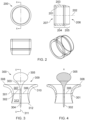
- FIG. 2 illustrates an example straight duct design for a ducted fan.
- the duct 200 has a circular cross section and comprises an inner surface 201 defining a uniform cross-sectional area along a longitudinal axis 202 of the duct 200.
- An outer surface 203 of the duct has a uniform diameter along a first portion 204 of the duct 200 and a tapering diameter along a second portion 205 of the duct 200 towards an outlet end 206.
- a rotor (not shown) provided within the interior of the duct forces airflow through the duct 200 from an inlet 207 to the outlet 206, providing thrust for an aircraft.
- a general problem to be addressed is how to improve the hover lift efficiency of a ducted fan propulsion system.
- a ducted fan aircraft propulsion system comprising:
- the reducing air flow passage encourages a larger volume of air into the duct, which aids lift due to the flared inlet end of the annular wing, thereby improving the hover lift efficiency of the aircraft.
- the duct may comprise an outwardly flared outlet end such that an outlet air flow passage between the central body portion and the inner surface of the duct has a sectional area that increases from the rotor to the outlet end of the duct.
- the increase in sectional area from the rotor to the outlet end of the duct may be smaller than the decrease in sectional area from the inlet end to the rotor.
- the duct may form an annular wing having a decreasing cross-section from the inlet end of the duct to the outlet end of the duct.
- the rotor may be positioned within the duct extending across a minimum of the sectional area of the duct.
- An upper part of an outer surface of the payload portion may define a spheroidal shape.
- the spheroidal shape may for example be an oblate spheroid having a shorter axis along a longitudinal axis of the central body portion.
- a lower part of the outer surface of the payload portion may taper from the spheroidal shape to the central body portion.
- the central body portion may comprise a motor connected to drive the rotor via a rotor shaft.
- the motor may be electric.
- the system may comprise an electric storage unit and an electric power controller configured to provide electric power to the motor.
- an aircraft comprising a ducted fan propulsion system according to the first aspect.
- the aircraft may comprise a single ducted fan propulsion system.
- the duct may form an outer fuselage of the aircraft.
- the aircraft may be a coleopter.
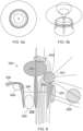
- FIGs 3, 4 , 5a and 5b illustrate an example design for a ducted fan propulsion system 300.
- the system 300 comprises a duct 301 surrounding a central body portion 302.
- the central body portion 302 extends through the duct 301 from a first end 303 to a second end 304.
- a payload portion 305 extends from the first end 303 of the central body portion 302.
- a rotor 306 extends across an internal volume 307 of the duct from the central body portion 302.
- the system 300 is rotationally symmetric about a central axis 311 extending through the central body portion 302.
- the duct 301 comprises an outwardly flared inlet end 308 such that an annular inlet air flow passage 309 between an outer surface of the central body portion 302 and an inner surface 310 of the duct 301 has a sectional area that decreases from the inlet end 308 of the duct 301 to the rotor 306.
- the duct 301 also comprises an outwardly flared outlet end 312 such that an outlet air passage 313 between the central body portion 302 and the inner surface 310 of the duct 301 has a sectional area that increases from the rotor 306 to the outlet end 312.
- the cross-sectional shape of the duct 301 forms an annular wing having a decreasing cross-section from the inlet end 308 of the duct 301 to the outlet end 312 of the duct 301.
- the annular wing shape enhances lift of the propulsion system 300 due to airflow through the duct 301. More thrust can thereby be achieved at lower power values, leading to improved hover efficiency.
- the rotor 306 is positioned in the middle of the duct 301 at a position where the sectional area of the duct 301 is at a minimum.
- the payload portion 305 in Figure 3 has an upper portion with an outer surface that defines a spheroidal shape.
- the spheroidal shape in the illustrated example is an oblate spheroid having a shorter axis along the longitudinal axis 311 of the central body portion 302.
- the payload portion 305 may take other shapes, for example a spherical shape or a prolate spheroidal shape.
- Figure 4 illustrates a sectional view of the system 300, which is taken along section A-A indicated in Figure 3 .
- Figures 5a and 5b illustrate a top view and a side view respectively of the system 300.
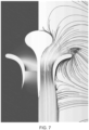
- Figure 6 is a schematic diagram illustrating how the various geometries of the system 300 increase lift and reduce the work done by the rotor or fan 306.
- the outwardly flared inlet 308 encourages a larger volume 601 of air into the fan 306, with a reducing sectional area between the inlet 308 and the fan 306 having reduced obstruction to airflow.
- the shape of the payload body 305 forms an accelerated flow of air 602 over the payload body 305 and into the duct inlet 603.
- the shape of the payload body 305 in combination with the outwardly flared shape of the duct inlet end forms a smooth and compressing flow of air through the duct inlet 603.
- the outwardly flared inlet end 308 maintains a high-pressure volume 604 under annular wing shape of the duct inlet 308, which increases suction over the wing.
- a low-pressure region 605 is created within the duct between the fan 306 and the duct outlet 606, which creates a high pressure underneath the duct body with expansion at the duct outlet 606.
- Airflow 607 around the outer surface of the duct is directed to the inlet 603 and speeded up over the annular wing of the duct. Airflow 608 further away from the duct is not blocked by the annular wing.
- Figure 6 illustrates results from an Ansys Fluent computational fluid dynamics (CFD) model of the duct and central body portion with the payload portion.
- CFD Ansys Fluent computational fluid dynamics
- the left half of the plot illustrates static pressure, while the right half illustrates velocity streamlines. These are illustrated separately, with associated pressure values and velocity magnitudes, in Figures 8 and 9 .
- FIG 10 illustrates schematically an example aircraft 1000 with a propulsion system based on the duct design described above.
- the aircraft 1000 comprises the propulsion system as described above in relation to Figures 3-5 .
- a motor 1001 connected to drive a rotor shaft 1004 connected to the rotor 306.
- the motor 1001 may be an electric motor, which is powered from an electric storage unit 1003 with an electric power controller 1002.
- the electric storage unit 1003 may comprise a battery module.
- the electric power controller 1002 may function to control electric power provided to the motor 1002 and to maintain a required voltage supply using a power converter module that is provided with a DC voltage supply from the storage unit 1003.
- the electric storage unit 1003, controller 1002 and electric motor 1001 may be provided in the payload portion 305, in the central body portion 302 or distributed between the payload portion 305 and the central body portion 302.
- the central body portion 302 and the duct 301 are connected to each other by a plurality of struts 1004 extending between the central body portion 302 and the inner surface 310 of the duct 301.
- the struts 1004 are illustrated in Figure 10 as extending across an inlet end of the duct 301, but may be provided elsewhere, for example towards the outlet end or closer to the rotor 306 on either the inlet or outlet side.
- a single ducted propulsion system forms the aircraft 1000, making the aircraft take the form of a coleopter.
- the aircraft may comprise a plurality of ducted fan propulsion systems linked together. Linking multiple systems together may improve stability of the aircraft, particularly during hover.
- the rotor or fan 306 of the aircraft 1000 may be around 3m in diameter.
- the fan may have a maximum speed of 2000 RPM and with a power consumption of around 1100 kW.
- the duct 301 may have a maximum outer diameter of around 6m.
- the shape of the duct 301 is designed in conjunction with the payload body 305 to increase the vehicle lift efficiency, as described above.
- an outer diameter of the rotor may be between around 2 and 4 metres and a maximum outer diameter of the duct may be between around 5 and 10 metres.
- a total weight of the aircraft may be between around 2 and 10 tonnes.
Landscapes
- Engineering & Computer Science (AREA)
- Aviation & Aerospace Engineering (AREA)
- Chemical & Material Sciences (AREA)
- Combustion & Propulsion (AREA)
- Mechanical Engineering (AREA)
- Structures Of Non-Positive Displacement Pumps (AREA)
Applications Claiming Priority (1)
| Application Number | Priority Date | Filing Date | Title |
|---|---|---|---|
| GBGB2313173.3A GB202313173D0 (en) | 2023-08-30 | 2023-08-30 | Ducted fan aircraft propulsion system |
Publications (1)
| Publication Number | Publication Date |
|---|---|
| EP4520660A1 true EP4520660A1 (fr) | 2025-03-12 |
Family
ID=88237207
Family Applications (1)
| Application Number | Title | Priority Date | Filing Date |
|---|---|---|---|
| EP24192296.2A Withdrawn EP4520660A1 (fr) | 2023-08-30 | 2024-08-01 | Système de propulsion d'aéronef à soufflante carénée |
Country Status (3)
| Country | Link |
|---|---|
| US (1) | US12404007B2 (fr) |
| EP (1) | EP4520660A1 (fr) |
| GB (1) | GB202313173D0 (fr) |
Citations (8)
| Publication number | Priority date | Publication date | Assignee | Title |
|---|---|---|---|---|
| DE944102C (de) * | 1955-06-23 | 1956-06-07 | Gerhard Siegel | Autorotationsfaehiger Hub- und Flugschrauber |
| US3128062A (en) * | 1961-07-19 | 1964-04-07 | Brocard Jean Marie Rene | Aircraft |
| US3135481A (en) * | 1961-07-17 | 1964-06-02 | Helipod Inc | Ducted rotor aircraft |
| GB1540068A (en) * | 1976-01-10 | 1979-02-07 | Benson W | Propulsion apparatus |
| US5295643A (en) * | 1992-12-28 | 1994-03-22 | Hughes Missile Systems Company | Unmanned vertical take-off and landing, horizontal cruise, air vehicle |
| US5996933A (en) * | 1995-10-28 | 1999-12-07 | Schier; Johannes | Aircraft |
| US20110147533A1 (en) * | 2009-12-21 | 2011-06-23 | Honeywell International Inc. | Morphing ducted fan for vertical take-off and landing vehicle |
| CN211810264U (zh) * | 2019-09-11 | 2020-10-30 | 李笑一 | 一种中喷流升空托举装置及基于升空托举装置的飞行器 |
Family Cites Families (23)
| Publication number | Priority date | Publication date | Assignee | Title |
|---|---|---|---|---|
| US1440242A (en) * | 1922-03-02 | 1922-12-26 | Porter James Robertson | Propulsion means for vessels |
| NL110393C (fr) * | 1955-11-29 | 1965-01-15 | Bertin & Cie | |
| US3054578A (en) * | 1957-10-08 | 1962-09-18 | Cie De Rech S Et D Etudes Aero | Annular aircraft with elastic collector ring rim |
| US2967029A (en) * | 1958-07-21 | 1961-01-03 | Charles L Hill | Aircraft vertical lift device |
| US3066888A (en) * | 1959-06-29 | 1962-12-04 | Edmond R Doak | Energy-absorbing protective element for aircraft |
| US3101917A (en) * | 1961-11-27 | 1963-08-27 | Helipod Inc | Ducted rotor with pressure balancing and lift augmenting means |
| US3276723A (en) * | 1964-02-28 | 1966-10-04 | Astro Kinetics Corp | Vtol flight unit |
| US4446696A (en) | 1981-06-29 | 1984-05-08 | General Electric Company | Compound propulsor |
| US4795111A (en) * | 1987-02-17 | 1989-01-03 | Moller International, Inc. | Robotic or remotely controlled flying platform |
| US6698685B2 (en) * | 2002-01-08 | 2004-03-02 | Eric Ronald Walmsley | Circular vertical take off and landing aircraft |
| JP2002337794A (ja) | 2001-05-18 | 2002-11-27 | Tsuneo Kayama | ドーナツ型気球の中心部に回転翼を取付けた飛行機 |
| US7201346B2 (en) * | 2003-04-25 | 2007-04-10 | Brad C Hansen | Circular fixed wing VTOL aircraft |
| JP2009513435A (ja) | 2005-11-01 | 2009-04-02 | アーバン エアロノーティクス リミテッド | 屋根と床の流れ |
| US10450063B1 (en) | 2007-06-05 | 2019-10-22 | American Aviation Technologies, Llc | Aircraft having VTOL, translational and traverse flight |
| WO2011159374A2 (fr) * | 2010-03-08 | 2011-12-22 | The Penn State Research Foundation | Ventilateur à double conduite |
| US20150226086A1 (en) | 2014-02-03 | 2015-08-13 | Devin Glenn Samuelson | Rotational ducted fan (rdf) propulsion system |
| JP6554282B2 (ja) | 2014-12-24 | 2019-07-31 | 川崎重工業株式会社 | 航空機用エンジン装置 |
| US9975633B1 (en) * | 2016-05-10 | 2018-05-22 | Northrop Grumman Systems Corporation | Collapsible ducted fan unmanned aerial system |
| US10676205B2 (en) | 2016-08-19 | 2020-06-09 | General Electric Company | Propulsion engine for an aircraft |
| CN108883826A (zh) * | 2017-08-31 | 2018-11-23 | 深圳市大疆创新科技有限公司 | 动力装置及单旋翼无人飞行器 |
| WO2019190821A1 (fr) * | 2018-03-29 | 2019-10-03 | Walmart Apollo, Llc | Système de protection de sécurité mobile pour hélices de véhicule aérien sans pilote |
| PH12020551665B1 (en) * | 2018-04-24 | 2024-01-31 | Thomas W Melcher | Electric vertical takeoff and landing aircraft |
| US11584509B2 (en) * | 2019-06-27 | 2023-02-21 | Supra Lumina Technologies Inc. | Axial flow ducted fan with a movable section |
-
2023
- 2023-08-30 GB GBGB2313173.3A patent/GB202313173D0/en not_active Ceased
-
2024
- 2024-08-01 EP EP24192296.2A patent/EP4520660A1/fr not_active Withdrawn
- 2024-08-02 US US18/792,688 patent/US12404007B2/en active Active
Patent Citations (8)
| Publication number | Priority date | Publication date | Assignee | Title |
|---|---|---|---|---|
| DE944102C (de) * | 1955-06-23 | 1956-06-07 | Gerhard Siegel | Autorotationsfaehiger Hub- und Flugschrauber |
| US3135481A (en) * | 1961-07-17 | 1964-06-02 | Helipod Inc | Ducted rotor aircraft |
| US3128062A (en) * | 1961-07-19 | 1964-04-07 | Brocard Jean Marie Rene | Aircraft |
| GB1540068A (en) * | 1976-01-10 | 1979-02-07 | Benson W | Propulsion apparatus |
| US5295643A (en) * | 1992-12-28 | 1994-03-22 | Hughes Missile Systems Company | Unmanned vertical take-off and landing, horizontal cruise, air vehicle |
| US5996933A (en) * | 1995-10-28 | 1999-12-07 | Schier; Johannes | Aircraft |
| US20110147533A1 (en) * | 2009-12-21 | 2011-06-23 | Honeywell International Inc. | Morphing ducted fan for vertical take-off and landing vehicle |
| CN211810264U (zh) * | 2019-09-11 | 2020-10-30 | 李笑一 | 一种中喷流升空托举装置及基于升空托举装置的飞行器 |
Also Published As
| Publication number | Publication date |
|---|---|
| US20250074577A1 (en) | 2025-03-06 |
| US12404007B2 (en) | 2025-09-02 |
| GB202313173D0 (en) | 2023-10-11 |
Similar Documents
| Publication | Publication Date | Title |
|---|---|---|
| JP7401545B2 (ja) | 回転翼とその設計方法 | |
| CN109110137B (zh) | 用于航空器的推进系统及其操作方法 | |
| US5150859A (en) | Wingtip turbine | |
| EP2948633B1 (fr) | Ensemble aube pour système non caréné de production de poussée | |
| EP3666645B1 (fr) | Aéronef à ailes en flèche avant à ingestion de couche limite et système de propulsion électrique distribué | |
| US20190256189A1 (en) | Geometric morphing wing with adaptive corrugated structure | |
| EP1056640B1 (fr) | Rotor a vitesse optimale | |
| US6113029A (en) | Aircraft capable of hovering and conventional flight | |
| US20100294878A1 (en) | Flying body | |
| CN107458598A (zh) | 使用叶片桨距固定的马达模块的矩阵的反扭矩控制 | |
| CN111976970B (zh) | 用于飞行器的翼组结构以及具有这种翼组结构的飞行器 | |
| US2730311A (en) | Impeller propelled aerodynamic body | |
| CN111846215B (zh) | 一种尾推式无舵面双涵道无人飞行器 | |
| CN113978703B (zh) | 一种航空用的轮缘驱动式涵道推进器 | |
| EP4520660A1 (fr) | Système de propulsion d'aéronef à soufflante carénée | |
| CN114802733B (zh) | 涵道风扇及飞行装置 | |
| CN110513217B (zh) | 一种无人机涵道风扇动力系统 | |
| CN116176830A (zh) | 高推重比涵道风扇 | |
| KR102949884B1 (ko) | 양력 강화 조립체 | |
| EP3064431B1 (fr) | Hélice de réduction de décrochage | |
| CN211008891U (zh) | 一种无人机涵道风扇动力系统 | |
| CN108163213B (zh) | 一种多级增压无风叶式空气推进方法及推进装置 | |
| CN113443124B (zh) | 采用两级大小叶片的边界层吸入式推进器 | |
| EP4086167B1 (fr) | Aéronef avec des ventilateurs distribués pour une ingestion de la couche limite | |
| US20190101128A1 (en) | Wing or blade design for wingtip device, rotor, propeller, turbine, and compressor blades with energy regeneration |
Legal Events
| Date | Code | Title | Description |
|---|---|---|---|
| PUAI | Public reference made under article 153(3) epc to a published international application that has entered the european phase |
Free format text: ORIGINAL CODE: 0009012 |
|
| STAA | Information on the status of an ep patent application or granted ep patent |
Free format text: STATUS: THE APPLICATION HAS BEEN PUBLISHED |
|
| AK | Designated contracting states |
Kind code of ref document: A1 Designated state(s): AL AT BE BG CH CY CZ DE DK EE ES FI FR GB GR HR HU IE IS IT LI LT LU LV MC ME MK MT NL NO PL PT RO RS SE SI SK SM TR |
|
| STAA | Information on the status of an ep patent application or granted ep patent |
Free format text: STATUS: THE APPLICATION IS DEEMED TO BE WITHDRAWN |
|
| 18D | Application deemed to be withdrawn |
Effective date: 20250913 |