EP4520863A1 - Système de blanchisserie avec fourniture améliorée de vapeur surchauffée - Google Patents
Système de blanchisserie avec fourniture améliorée de vapeur surchauffée Download PDFInfo
- Publication number
- EP4520863A1 EP4520863A1 EP24195928.7A EP24195928A EP4520863A1 EP 4520863 A1 EP4520863 A1 EP 4520863A1 EP 24195928 A EP24195928 A EP 24195928A EP 4520863 A1 EP4520863 A1 EP 4520863A1
- Authority
- EP
- European Patent Office
- Prior art keywords
- hot steam
- laundry
- thermal battery
- heat
- heat exchanger
- Prior art date
- Legal status (The legal status is an assumption and is not a legal conclusion. Google has not performed a legal analysis and makes no representation as to the accuracy of the status listed.)
- Pending
Links
Images



Classifications
-
- D—TEXTILES; PAPER
- D06—TREATMENT OF TEXTILES OR THE LIKE; LAUNDERING; FLEXIBLE MATERIALS NOT OTHERWISE PROVIDED FOR
- D06F—LAUNDERING, DRYING, IRONING, PRESSING OR FOLDING TEXTILE ARTICLES
- D06F95/00—Laundry systems or arrangements of apparatus or machines; Mobile laundries
-
- D—TEXTILES; PAPER
- D06—TREATMENT OF TEXTILES OR THE LIKE; LAUNDERING; FLEXIBLE MATERIALS NOT OTHERWISE PROVIDED FOR
- D06F—LAUNDERING, DRYING, IRONING, PRESSING OR FOLDING TEXTILE ARTICLES
- D06F39/00—Details of washing machines not specific to a single type of machines covered by groups D06F9/00 - D06F27/00
- D06F39/04—Heating arrangements
-
- D—TEXTILES; PAPER
- D06—TREATMENT OF TEXTILES OR THE LIKE; LAUNDERING; FLEXIBLE MATERIALS NOT OTHERWISE PROVIDED FOR
- D06F—LAUNDERING, DRYING, IRONING, PRESSING OR FOLDING TEXTILE ARTICLES
- D06F39/00—Details of washing machines not specific to a single type of machines covered by groups D06F9/00 - D06F27/00
- D06F39/30—Arrangements for energy recovery
-
- D—TEXTILES; PAPER
- D06—TREATMENT OF TEXTILES OR THE LIKE; LAUNDERING; FLEXIBLE MATERIALS NOT OTHERWISE PROVIDED FOR
- D06F—LAUNDERING, DRYING, IRONING, PRESSING OR FOLDING TEXTILE ARTICLES
- D06F39/00—Details of washing machines not specific to a single type of machines covered by groups D06F9/00 - D06F27/00
- D06F39/40—Steam generating arrangements
Definitions
- the invention relates to a laundry system for the energy-reduced treatment of laundry, comprising several laundry treatment machines which are designed to treat the laundry with hot steam.
- the waste heat from laundry processing machines can be in the form of higher-temperature wastewater, while so-called exhaust air from the laundry processing machines can also be collected via the waste heat collection system. If the wastewater and/or exhaust air are fed to a heat exchanger at a higher temperature, the heat contained can be used for other systems.
- a laundry system of the present invention is understood to be an overall system of a laundry facility in which several laundry treatment machines are operated simultaneously or sequentially, but in a network.
- Such laundry systems generally have a superheated steam preparation system operated with conventional combustion systems based on oil or gas to generate the superheated steam from the supplied water.
- Laundry systems are energy-intensive, and the use of photovoltaics, wind power, and hydropower as renewable energy sources makes sense for laundry systems.
- electricity from so-called volatile energy sources should be used as efficiently as possible. without, however, using electricity to permanently heat water directly to generate hot steam.
- the DE 10 2021 113 134 A1 discloses a method for operating, preferably for supplying energy, a laundry with a plurality of laundry treatment machines that can be supplied with energy from at least one network, wherein the at least one network is fed by renewable energy or renewable energies, preferably electrical energy and/or biogas obtained from plants or renewable raw materials and/or hydrogen obtained from renewable energy.
- renewable energy or renewable energies preferably electrical energy and/or biogas obtained from plants or renewable raw materials and/or hydrogen obtained from renewable energy.
- the renewable energies can also be generated from wind power and/or hydropower and/or photovoltaics and/or biomass.
- the object of the invention is to improve a laundry system for the energy-reduced treatment of laundry, so that the laundry system can be operated even better with electricity from renewable energy sources, in particular without or with only a minimal use of fossil fuels.
- the invention provides the technical teaching that a central thermal battery is set up with which hot steam can be provided to the laundry treatment machines, wherein the central thermal battery is independent of the time of the provision of the
- the central thermal battery is designed such that it can be charged independently of the time at which hot steam is drawn from the thermal battery or when hot steam can or should be provided by the thermal battery.
- Charging the thermal battery describes heating a heat accumulator of the thermal battery to temperatures suitable for generating the hot steam required for operating the laundry treatment machines.
- the thermal battery can, for example, be constructed with pipes and a thermal storage material, with the pipes being enclosed by the thermal storage material.
- thermal batteries with pipes encased in thermal concrete are known from Energynest A/S.
- Such thermal batteries can be constructed with a storage medium that flows through the pipes and, under increased pressure, can reach temperatures of up to 450°C or even 500°C.
- the thermal battery can therefore be heated by means of an electric heater, and, for example, through the circulation of the storage medium, the thermal storage material, such as thermal concrete, can reach correspondingly high temperatures.
- the thermal energy present in the thermal storage material can be retained for a long time, so that the time window for charging the thermal battery, i.e., heating the thermal storage material, and the time window for extracting the energy by generating hot steam can differ significantly; for example, 24 hours or more can elapse between the two times.
- the time difference made possible by the thermal battery between charging the thermal battery with thermal energy via the electric heater and extracting the heat to provide hot steam enables the particularly intensive use of renewable energies, which are not always available. If renewable energy is available inexpensively via wind energy, solar energy, or hydropower, for example, the thermal battery can be charged to its maximum using a control device in the laundry system, ensuring that the thermal storage material reaches a maximum temperature. Due to the long storage capacity of the heat, hot steam can also be generated at a much later time using the heat still stored in the thermal battery when the laundry system and laundry treatment machines are put into operation.
- control device is configured to receive availability information about the availability of renewable energy and/or conventional energy via a data line.
- control device can record weather data, particularly regarding wind and/or solar radiation.
- control device can be fed with the operating data and operating times of the laundry system.
- control device can have an AI module, thus enabling or utilizing artificial intelligence.
- the control device is designed, in particular, to control the heat pump and/or the inflow of wastewater and/or exhaust air to the heat pump and/or the transfer of hot steam from the heat pump to the hot steam storage tank and/or the hot steam from the thermal battery to the hot steam storage tank.
- the most important components of the laundry system can be controlled by means of the Control equipment should be operated as energy-efficiently and cost-effectively as possible.
- a valve is installed in the wastewater collection line between the waste heat storage tank and the heat pump, and/or a valve is installed in the steam line between the heat pump and the superheated steam storage tank, and/or a valve is installed in the steam line between the thermal battery and the superheated steam storage tank or the heat exchanger, and/or an electrical switching point is installed in the electrical line between the energy sources, i.e., wind energy, solar energy, hydropower, and/or conventional energy.
- the valves and the electrical switching point are each controllable by the control device. This allows the fluid flows of the superheated steam and the cost-optimized connection of the energy type to be controlled.
- the heat pump can be operated even when the laundry system is not running, in order to empty the waste heat storage tank and fill the hot steam storage tank with hot steam.
- the thermal battery which can be heated with the electric heater, especially when a large proportion of renewable energy is available.
- the control device can adjust the inflow of hot steam from the thermal battery or from the heat pump in such a way that not only minimal costs are incurred for the current operating point of the laundry system, but also, for example, whether a a larger or smaller proportion of renewable energy is available.
- the same can also be tracked, for example, via the electricity price of conventional energy. This is then used when, for example, the electricity price is low and little renewable energy is available.
- This principle can also be learned and progressively optimized by the control device over a longer period of time, for which the control device can have an AI module.
- Solar energy sources, wind energy sources, and/or, depending on the location, hydropower can also be part of the laundry system, for example, in conjunction with building technology.
- the solar energy sources, wind energy sources, and/or hydropower sources can also be public or private providers, with a specified energy mix used for power generation.
- a conventional energy provider can also be used to cover peak loads, for example, if no renewable energy source is currently available.
- the thermal battery can have a water supply via which water can be supplied to the thermal battery, and the thermal battery can be designed to convert the water into hot steam with a temperature of, for example, 135°C to 165°C, and preferably of approximately 150°C.
- Providing superheated steam of, for example, 150°C is also possible if the thermal storage material has been heated to significantly higher temperatures, for example, 400°C to 500°C or higher, using an electric heater.
- Providing superheated steam at a significantly lower temperature can be achieved by appropriate pressure and temperature control of the evaporating water. In this respect, it is possible to supply water directly to the thermal battery, which can flow through the pipes to generate the superheated steam.
- the thermal battery can be filled with a storage medium that reaches the temperature of the thermal storage material, for example, 400°C to 500°C or more, wherein a heat exchanger is set up which is connected to the thermal battery by at least one pipe, so that the storage medium can be guided through the heat exchanger by means of the pipe.
- the heat exchanger can then be operated with water on the heat-absorbing side to generate the hot steam in the heat exchanger.
- the heat exchanger can also be set up as a structural unit with the thermal battery itself, so that water is then also supplied to the thermal battery and the water evaporates on the heat-absorbing side of the heat exchanger, with the storage medium flowing through the heat exchanger on the heat-emitting side.
- the provision of a heat exchanger and the use of a storage medium therefore represents an alternative to the direct evaporation of water to hot steam in the pipes of the thermal battery.
- a hot steam storage for storing the hot steam, and from the hot steam storage the Laundry machines are supplied with superheated steam.
- the superheated steam storage can also be appropriately insulated, allowing the superheated steam to be stored in the superheated steam storage for extended periods of time, ensuring that it still has a sufficiently high temperature for later use by the laundry machines.
- Superheated steam can be supplied to the superheated steam storage directly from the thermal battery, or it can be supplied to the superheated steam storage from the heat exchanger, with the heat exchanger connected to the superheated steam storage via at least one pipe.
- Such time-dependent operation of the laundry system can be controlled by the control unit, which is part of the laundry system.
- the control unit can thus control both the charging of the thermal battery and the filling of the superheated steam storage tank with superheated steam, depending on when and at what price renewable energy sources are available and when or at what time the laundry system needs to be put into operation.
- the use of a conventional energy source based on fossil fuels can also be included in the system, but these energy sources are then only used by the control system to cover peak loads if the available renewable energy sources are not sufficient.
- a central heat pump is configured, which has an evaporator unit and a condenser unit, wherein, in conjunction with the condenser unit, additional superheated steam can be generated.
- the superheated steam generated by the condenser unit can also be fed to the superheated steam storage unit.
- the laundry system has a waste heat collection device, in particular with a waste heat storage device, wherein the evaporator unit of the heat pump is configured in connection with the waste heat collection device and/or with the waste heat storage device.
- the heat pump can in particular also only be put into operation when renewable energy is available, with which the heat pump can be operated to generate hot steam and supply it to the hot steam storage device.
- the waste heat storage device in the waste heat collection device can also be insulated, so that the waste water and/or the exhaust air from the laundry treatment machines can be stored in the waste heat storage device in order to be used to operate the heat pump at a later time, for example when renewable energy is available.
- the control device can also take over the operation of the heat pump and, for example, also monitors the temperature of the waste heat in the waste heat storage device of the waste heat collection device.
- At least one of the laundry treatment machines can have a process chamber in which or in connection with which a heat exchanger is installed, in particular in spatial-structural Unit with the laundry treatment machine.
- the storage medium of the thermal battery can be routed through this heat exchanger in the process chamber of the laundry treatment machine, so that in the heat exchanger, water can be converted directly from a water supply into hot steam, which can be used to operate the laundry treatment machine.
- the storage medium from the thermal battery can have a higher temperature than the required temperature of the hot steam, even if the heating of the thermal battery via the electric heater took place several hours or even days ago.
- the variant with the heat exchangers in the laundry treatment machine eliminates the need for a hot steam storage unit.
- the object of the invention is further achieved by a method for operating a laundry system for the energy-reduced treatment of laundry, comprising a plurality of laundry treatment machines, by means of which the laundry is treated with hot steam, wherein the method comprises at least the following further steps: Setting up a central thermal battery, with which hot steam can be provided to the laundry treatment machines; Charging the central thermal battery at a time when electrical power from renewable energy sources is available and/or usable and providing the hot steam to the laundry treatment machines during their operating time.
- the hot steam can be generated directly in the thermal battery or the thermal battery can be A storage medium, such as silicone oil or the like, is used to transfer thermal energy to the hot steam or water via a heat exchanger, which is then converted into hot steam through subsequent evaporation.
- a storage medium such as silicone oil or the like
- the hot steam is generated directly in the thermal battery and fed into a hot steam storage unit.
- the hot steam generated in the thermal battery can also be fed directly to the at least one laundry treatment machine.
- a heat exchanger can utilize the heat from the storage medium to generate superheated steam.
- the heat exchanger is connected to the thermal battery via a pipe. If water is added to the heat exchanger, it can evaporate in the heat-absorbing side of the heat exchanger and be converted into superheated steam, while the storage medium cools in the heat exchanger.
- the storage medium can, for example, circulate in a circuit between the heat exchanger and the thermal battery.
- the method provides that at least one laundry treatment machine has a process chamber in which or in connection with which a heat exchanger is arranged, wherein the storage medium of the thermal battery is guided via the heat exchanger, and wherein hot steam is generated from a water supply directly in the laundry treatment machine for operating the at least one laundry treatment machine with the heat exchanger.
- the method can provide for setting up a central heat pump which has an evaporator unit and a condenser unit, wherein in connection with the condenser unit additionally Hot steam is generated and/or wherein a waste heat collection device and/or a waste heat storage device is or are set up, wherein the evaporator unit is set up in connection with the waste heat collection device and/or with the waste heat storage device and heat from the waste heat collection device and/or the waste heat storage device is used for the evaporator unit.
- a control device can be set up to which information about the availability of renewable energy, in particular from wind energy, solar energy, hydropower and/or from conventional energy is supplied, and wherein the control device switches the electrical heating of the thermal battery and/or the heat pump on or off in such a way that a maximum of renewable energy sources is used.
- the temperature of the waste heat storage tank, the temperature of the thermal battery, and/or the temperature of the hot steam storage tank can be monitored via appropriate sensors, and the temperature values can be retrieved by the control unit.
- an operating plan for the laundry system can be programmed into the control unit, allowing the controller to plan in advance the use and/or storage, i.e., the future use, of thermal energy from the waste heat storage tank, the hot steam storage tank, and/or the thermal battery.
- weather data can be programmed into the control unit or made available online, allowing the control unit to incorporate future availability of renewable energy sources into the control of the laundry system, particularly the operation of the electrical heating of the thermal battery.
- the control device can, for example, also use the heat still available in the waste heat storage of the waste heat collection device and the current temperature of the thermal battery determine whether the hot steam is generated primarily with the thermal battery or predominantly with the heat pump. For example, if the waste heat storage still contains a significant amount of thermal energy, it may be more energy-efficient not to immediately switch on the thermal battery's electric heating, even if renewable energy is available, but rather to first utilize the remaining heat in the waste heat storage, as this would otherwise be lost.
- the control device can be capable of learning about the resulting energy consumption over a longer period of use, particularly by using artificial intelligence, which is expressed, for example, by optimising the use of heat in the waste heat storage unit, optimising the energy to be kept available in the hot steam storage unit and/or in the thermal battery, and by ensuring that the total energy required to operate the laundry system over a longer period of time is kept to a minimum.
- artificial intelligence which is expressed, for example, by optimising the use of heat in the waste heat storage unit, optimising the energy to be kept available in the hot steam storage unit and/or in the thermal battery, and by ensuring that the total energy required to operate the laundry system over a longer period of time is kept to a minimum.
- FIG. 1 A schematic representation of a laundry system 100 with the features of the invention is shown.
- the illustration shows, by way of example, three laundry treatment machines 10, 11, 12, which include, for example, a mangle, a drum dryer, and a tunnel finisher.
- the laundry treatment machines 10, 11, 12 shown require superheated steam 13 as a process medium for treating the laundry, for example, after a previous washing process.
- the superheated steam 13 can, for example, have an overpressure of 2 bar at a temperature of 135°C to 165°C.
- a pipe network is shown which connects the laundry treatment machines 10, 11, 12 to a central hot steam storage 22 in which the hot steam 13 is stored, and the hot steam 13 reaches the individual laundry treatment machines 10, 11, 12.
- the laundry system 100 comprises a thermal battery 14.
- the thermal battery 14 can store energy in the form of heat that has previously been introduced into the thermal battery 14.
- the thermal battery is distinguished by the fact that it comprises, for example, pipes 15 enclosed in a thermal storage material 16.
- the thermal storage material 16 forms the mass that can be heated and stores the heat due to its very high specific heat capacity, so that a very large amount of heat in joules can be stored in a given volume of the thermal storage material 16.
- this material can store heat in the thermal storage material 16 for a long period of time until, for example, a medium is passed through the pipes 15, which heats up against the thermal storage material 16, thereby simultaneously reducing the heat in the thermal storage material 16 and causing its temperature to drop again.
- Modern thermal batteries 14 can comprise thermal storage materials 16 that can reach temperatures of up to 500°C or even significantly higher. This temperature can be stored for a long period of time due to the good insulation of the thermal storage material 16 of the thermal battery 14. For example, it is conceivable to enclose the thermal storage material 16 with a vacuum jacket, similar to a thermos flask, or to use other highly insulating materials.
- the thermal battery 14 is a non-electrical heat storage device and may comprise a heat storage material and, for example, fluid lines, through which a hot medium can flow in order to heat the heat storage material, for example to several hundred degrees Celsius.
- the heat storage material of the thermal battery 14 can also be heated directly by means of an integrated electric heater.
- the heat storage material is designed and insulated in such a way that it can store the introduced heat over a long period of time, i.e., it maintains the temperature. Via a medium in the fluid lines of the thermal battery 14, the heat once introduced can thus be removed again at a later time, whereby the hot steam 13 can be formed by means of or from the medium.
- the thermal battery 14 may include an electric heater 17.
- This heater may be electrically operated using various energy sources, for example, wind energy 32, solar energy 33, or hydropower 34.
- a conventional energy source 35 may also be available if the renewable energy sources 32, 33, and 34 are temporarily unavailable.
- the operation of the electric heater 17 can be controlled by means of a control device 31, which supplies the electric heater 17 with energy and heats the thermal storage material 16 in particular when a particularly large amount of renewable energy is available, in particular at low cost.
- the exemplary embodiment shows a water supply 18 to the thermal battery 14, via which water can be supplied to the thermal battery 14.
- the supplied water can be converted into hot steam 13 in the thermal battery 14, for example, at a temperature of 150°C, so that this hot steam 13 is then fed into the hot steam storage 22 to be ready for the operation of the laundry treatment machines 10, 11, 12.
- FIG. 2 shows the laundry system 100 with the laundry treatment machines 10, 11, 12, as well as with the thermal battery 14, and the hot steam storage 22 shown stores hot steam 13, which can be provided to the laundry treatment machines 10, 11, 12 via a pipe network.
- a heat exchanger 20 is provided in this exemplary embodiment, which is connected to the thermal battery 14 via pipes 21.
- the storage medium 19 has a considerably higher temperature than the generated hot steam 13, wherein a quantity of storage medium 19 is supplied to the heat exchanger 20 via a control device (not shown in detail), which quantity is determined such that the water can be generated with a correct quantity of hot steam 13 at the correspondingly desired temperature.
- the operation of the electric heater 17 of the thermal battery 14 can be controlled via the control device 31 using wind energy 32, solar energy 33, hydropower 34 or alternatively using conventional energy 35.
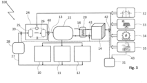
- FIG 3 shows a further exemplary embodiment of the laundry system 100 with a thermal battery 14, with which hot steam 13 can be provided to the hot steam accumulator 22 via the heat exchanger 20 in the manner described above.
- the laundry treatment machines 10, 11 and 12 can be operated with the hot steam 13 from the hot steam accumulator 22.
- the exemplary embodiment shows a waste heat collection device 27 in which a waste heat accumulator 28 is incorporated.
- the waste heat collection device 27 is configured to absorb the waste heat from the operation of the laundry treatment machines 10, 11 and 12, for example in the form of still warm waste water and/or in the form of exhaust air that the laundry treatment machines 10, 11, 12 generate during their operation.
- the waste heat accumulator 28 shown as an example is configured to store the waste water and/or the exhaust air at a correspondingly elevated temperature, typically at 70°C.
- the embodiment further shows a heat pump 24 which is designed to be operated with the waste heat from the operation of the laundry treatment machines 10, 11, 12 as primary heat and to generate hot steam 13 which can also be transferred to the hot steam storage 22.
- the heat pump 24 has, in a manner known per se, an evaporator unit 25 and a condenser unit 26, wherein the evaporator unit 25 can be operated with the waste heat from the waste heat collection device 27 or from the waste heat storage unit 28.
- the condenser unit 26 is designed to generate superheated steam 13 with the addition of water, which is transferred to the superheated steam storage unit 22.
- the heat pump 24 can also be operated with the energy sources shown, for example with wind energy 32, with Solar energy 33, with hydropower 34 or alternatively with conventional energy 35.
- the control device 31 is designed both to control the electrical heating of the thermal battery 14 and to control the operation of the heat pump 24.
- the control device 43 is configured to control the heat pump 24 and/or the inflow of wastewater and/or exhaust air to the heat pump 24 and/or the transfer of the hot steam 13 from the heat pump 24 to the hot steam storage tank 22 and/or the hot steam 13 from the thermal battery 14 to the hot steam storage tank 22.
- a valve 39 is provided in the waste heat collection device 27 between the waste heat accumulator 28 and the heat pump 24 and/or a valve 40 is provided in the steam line between the heat pump 24 and the hot steam accumulator 22 and/or a valve 41 is provided in the steam line between the thermal battery 14 and the hot steam accumulator 33 and/or an electrical switching point 42 is provided in the electrical line between the energy sources 32, 33, 34, 35, wherein the valves 39, 40, 41 and the electrical switching point 42 are each controlled by the control device 43.
Landscapes
- Engineering & Computer Science (AREA)
- Textile Engineering (AREA)
- Accessory Of Washing/Drying Machine, Commercial Washing/Drying Machine, Other Washing/Drying Machine (AREA)
Applications Claiming Priority (1)
| Application Number | Priority Date | Filing Date | Title |
|---|---|---|---|
| DE102023123892.2A DE102023123892A1 (de) | 2023-09-05 | 2023-09-05 | Wäschereisystem mit verbesserter Bereitstellung von Heißdampf |
Publications (1)
| Publication Number | Publication Date |
|---|---|
| EP4520863A1 true EP4520863A1 (fr) | 2025-03-12 |
Family
ID=92538439
Family Applications (1)
| Application Number | Title | Priority Date | Filing Date |
|---|---|---|---|
| EP24195928.7A Pending EP4520863A1 (fr) | 2023-09-05 | 2024-08-22 | Système de blanchisserie avec fourniture améliorée de vapeur surchauffée |
Country Status (2)
| Country | Link |
|---|---|
| EP (1) | EP4520863A1 (fr) |
| DE (1) | DE102023123892A1 (fr) |
Citations (4)
| Publication number | Priority date | Publication date | Assignee | Title |
|---|---|---|---|---|
| DE2117103A1 (de) * | 1971-04-07 | 1972-10-26 | Vitt, Gerhard, 5070 Bergisch Glad bach, Baur, Eduard, Dipl Ing , 5256 Waldbruch | Verfahren und Vorrichtung zum Erzeu gen eines erhitzten Mediums fur Beheizungs zwecke |
| DE102006020003A1 (de) | 2006-04-26 | 2007-10-31 | Herbert Kannegiesser Gmbh | Verfahren zur Rückgewinnung der von Wäschereimaschinen abgegebenen Wärmeenergie |
| DE102013213978A1 (de) * | 2013-07-17 | 2015-01-22 | Siemens Aktiengesellschaft | Abwärmenutzung von Hochtemperaturbatterien |
| DE102021113134A1 (de) | 2021-05-20 | 2022-11-24 | Herbert Kannegiesser Gmbh | Wäscherei und Verfahren zum Betreiben einer Wäscherei |
Family Cites Families (4)
| Publication number | Priority date | Publication date | Assignee | Title |
|---|---|---|---|---|
| DE10342653A1 (de) * | 2003-09-15 | 2005-04-07 | Miliauskaite, Asta, Dr. | Vorrichtung zur Erzeugung elektrischer Energie |
| DE102011109779A1 (de) * | 2011-08-09 | 2013-02-14 | Linde Aktiengesellschaft | Thermoelektrischer Energiespeicher |
| CN107964775B (zh) * | 2017-11-10 | 2019-05-03 | 珠海格力电器股份有限公司 | 一种洗衣房余热回收的供热系统及方法 |
| DE102022204303A1 (de) * | 2022-05-02 | 2023-11-02 | Heuft Besitzgesellschaft Gmbh & Co. Kg | Hochtemperatur-Thermoöl-Wärmespeicher |
-
2023
- 2023-09-05 DE DE102023123892.2A patent/DE102023123892A1/de active Pending
-
2024
- 2024-08-22 EP EP24195928.7A patent/EP4520863A1/fr active Pending
Patent Citations (4)
| Publication number | Priority date | Publication date | Assignee | Title |
|---|---|---|---|---|
| DE2117103A1 (de) * | 1971-04-07 | 1972-10-26 | Vitt, Gerhard, 5070 Bergisch Glad bach, Baur, Eduard, Dipl Ing , 5256 Waldbruch | Verfahren und Vorrichtung zum Erzeu gen eines erhitzten Mediums fur Beheizungs zwecke |
| DE102006020003A1 (de) | 2006-04-26 | 2007-10-31 | Herbert Kannegiesser Gmbh | Verfahren zur Rückgewinnung der von Wäschereimaschinen abgegebenen Wärmeenergie |
| DE102013213978A1 (de) * | 2013-07-17 | 2015-01-22 | Siemens Aktiengesellschaft | Abwärmenutzung von Hochtemperaturbatterien |
| DE102021113134A1 (de) | 2021-05-20 | 2022-11-24 | Herbert Kannegiesser Gmbh | Wäscherei und Verfahren zum Betreiben einer Wäscherei |
Also Published As
| Publication number | Publication date |
|---|---|
| DE102023123892A1 (de) | 2025-03-06 |
Similar Documents
| Publication | Publication Date | Title |
|---|---|---|
| EP2812542B1 (fr) | Centrale d'accumulation d'énergie et procédé de fonctionnement d'une telle centrale | |
| DE102007045888B4 (de) | Verfahren zur Umwandlung und Speicherung von regenerativer Energie | |
| DE102008047219A1 (de) | Verfahren zur Förderung von Bitumen und/oder Schwerstöl aus einer unterirdischen Lagerstätte, zugehörige Anlage und Betriebsverfahren dieser Anlage | |
| EP2224104B1 (fr) | Procédé destiné au fonctionnement d'une centrale | |
| EP0008680A2 (fr) | Procédé de production d'énergie thermique en combinant une unité de puissance thermique avec une pompe à chaleur | |
| EP2811124A1 (fr) | Dispositif d'accumulation d'énergie destinée au préchauffage d'eau d'alimentation | |
| DE2757306A1 (de) | Energiespeicher | |
| DE102018207195A1 (de) | Energiesystem zur Speicherung und Bereitstellung von Strom und Wärme | |
| EP4520863A1 (fr) | Système de blanchisserie avec fourniture améliorée de vapeur surchauffée | |
| EP3511534A1 (fr) | Centrale thermique et procédé de fonctionnement d'une centrale thermique | |
| EP4520865B1 (fr) | Système de blanchisserie et procédé de fonctionnement d'un système de blanchisserie | |
| WO2011045047A2 (fr) | Procédé à cycle (o)rc pour la transformation en énergie électrique de la chaleur produite lors de la combustion de biomasse et dispositif correspondant | |
| DE102017000199A1 (de) | Verfahren und System zur Erzeugung von Wärme, Strom und Wasserstoff mit einer reversiblen Brennstoffzelle und einem Wasserstoffspeicher | |
| DE102011101665B4 (de) | Wärmeeinheit zum Erzeugen elektrischer Energie und Verfahren zur Erzeugung von Strom aus Wärme | |
| DE102023005446A1 (de) | Wäschereisystem | |
| EP2708719A1 (fr) | Centrale à gaz destinée à accumuler de l'énergie | |
| DE202008001386U1 (de) | Heizanlage durch Anordnung eines Verbrennungsmotors mit Generator und Luft-Wasser Wärmepumpe | |
| DE102024102522A1 (de) | Wäschereisystem mit optimierter nutzung eingebrachter energie | |
| DE2732132A1 (de) | Verfahren und vorrichtung zur erzeugung von waerme | |
| EP1764561A1 (fr) | Procédé d'opération d'une installation de production d'énergie thermique | |
| EP4301966B1 (fr) | Centrale à accumulation et procédé pour faire fonctionner une centrale à accumulation | |
| AT523920A4 (de) | Gaserzeugungsvorrichtung zur Umwandlung elektrischer Energie in speicherbares Nutzgas | |
| DE102018214434A1 (de) | Anordnung aus einer Geschirrspülmaschine und einer Brennstoffzelle | |
| WO2011026633A2 (fr) | Procédé et dispositif de production d'énergie notamment à partir de biomasse ou de porteurs d'énergie de biomasse | |
| EP2573472A2 (fr) | Dispositif thermique avec pompe à chaleur et procédé destiné au fonctionnement d'un dispositif thermique avec pompe à chaleur |
Legal Events
| Date | Code | Title | Description |
|---|---|---|---|
| PUAI | Public reference made under article 153(3) epc to a published international application that has entered the european phase |
Free format text: ORIGINAL CODE: 0009012 |
|
| STAA | Information on the status of an ep patent application or granted ep patent |
Free format text: STATUS: THE APPLICATION HAS BEEN PUBLISHED |
|
| AK | Designated contracting states |
Kind code of ref document: A1 Designated state(s): AL AT BE BG CH CY CZ DE DK EE ES FI FR GB GR HR HU IE IS IT LI LT LU LV MC ME MK MT NL NO PL PT RO RS SE SI SK SM TR |
|
| STAA | Information on the status of an ep patent application or granted ep patent |
Free format text: STATUS: REQUEST FOR EXAMINATION WAS MADE |
|
| 17P | Request for examination filed |
Effective date: 20250904 |
|
| RAP1 | Party data changed (applicant data changed or rights of an application transferred) |
Owner name: BRINGEWATT, WILHELM |
|
| RIN1 | Information on inventor provided before grant (corrected) |
Inventor name: KRAEMER, JUERGEN |