EP4520926A1 - Spalt-messung zwischen dichtelementen eines gasturbinenmotors - Google Patents
Spalt-messung zwischen dichtelementen eines gasturbinenmotors Download PDFInfo
- Publication number
- EP4520926A1 EP4520926A1 EP24188107.7A EP24188107A EP4520926A1 EP 4520926 A1 EP4520926 A1 EP 4520926A1 EP 24188107 A EP24188107 A EP 24188107A EP 4520926 A1 EP4520926 A1 EP 4520926A1
- Authority
- EP
- European Patent Office
- Prior art keywords
- stator
- sensor
- knife edges
- gas turbine
- stator assembly
- Prior art date
- Legal status (The legal status is an assumption and is not a legal conclusion. Google has not performed a legal analysis and makes no representation as to the accuracy of the status listed.)
- Pending
Links
Images


Classifications
-
- F—MECHANICAL ENGINEERING; LIGHTING; HEATING; WEAPONS; BLASTING
- F01—MACHINES OR ENGINES IN GENERAL; ENGINE PLANTS IN GENERAL; STEAM ENGINES
- F01D—NON-POSITIVE DISPLACEMENT MACHINES OR ENGINES, e.g. STEAM TURBINES
- F01D11/00—Preventing or minimising internal leakage of working-fluid, e.g. between stages
- F01D11/001—Preventing or minimising internal leakage of working-fluid, e.g. between stages for sealing space between stator blade and rotor
-
- F—MECHANICAL ENGINEERING; LIGHTING; HEATING; WEAPONS; BLASTING
- F01—MACHINES OR ENGINES IN GENERAL; ENGINE PLANTS IN GENERAL; STEAM ENGINES
- F01D—NON-POSITIVE DISPLACEMENT MACHINES OR ENGINES, e.g. STEAM TURBINES
- F01D17/00—Regulating or controlling by varying flow
- F01D17/02—Arrangement of sensing elements
-
- F—MECHANICAL ENGINEERING; LIGHTING; HEATING; WEAPONS; BLASTING
- F01—MACHINES OR ENGINES IN GENERAL; ENGINE PLANTS IN GENERAL; STEAM ENGINES
- F01D—NON-POSITIVE DISPLACEMENT MACHINES OR ENGINES, e.g. STEAM TURBINES
- F01D11/00—Preventing or minimising internal leakage of working-fluid, e.g. between stages
- F01D11/02—Preventing or minimising internal leakage of working-fluid, e.g. between stages by non-contact sealings, e.g. of labyrinth type
-
- F—MECHANICAL ENGINEERING; LIGHTING; HEATING; WEAPONS; BLASTING
- F01—MACHINES OR ENGINES IN GENERAL; ENGINE PLANTS IN GENERAL; STEAM ENGINES
- F01D—NON-POSITIVE DISPLACEMENT MACHINES OR ENGINES, e.g. STEAM TURBINES
- F01D11/00—Preventing or minimising internal leakage of working-fluid, e.g. between stages
- F01D11/08—Preventing or minimising internal leakage of working-fluid, e.g. between stages for sealing space between rotor blade tips and stator
- F01D11/12—Preventing or minimising internal leakage of working-fluid, e.g. between stages for sealing space between rotor blade tips and stator using a rubstrip, e.g. erodible. deformable or resiliently-biased part
- F01D11/122—Preventing or minimising internal leakage of working-fluid, e.g. between stages for sealing space between rotor blade tips and stator using a rubstrip, e.g. erodible. deformable or resiliently-biased part with erodable or abradable material
-
- F—MECHANICAL ENGINEERING; LIGHTING; HEATING; WEAPONS; BLASTING
- F01—MACHINES OR ENGINES IN GENERAL; ENGINE PLANTS IN GENERAL; STEAM ENGINES
- F01D—NON-POSITIVE DISPLACEMENT MACHINES OR ENGINES, e.g. STEAM TURBINES
- F01D11/00—Preventing or minimising internal leakage of working-fluid, e.g. between stages
- F01D11/08—Preventing or minimising internal leakage of working-fluid, e.g. between stages for sealing space between rotor blade tips and stator
- F01D11/14—Adjusting or regulating tip-clearance, i.e. distance between rotor-blade tips and stator casing
-
- F—MECHANICAL ENGINEERING; LIGHTING; HEATING; WEAPONS; BLASTING
- F01—MACHINES OR ENGINES IN GENERAL; ENGINE PLANTS IN GENERAL; STEAM ENGINES
- F01D—NON-POSITIVE DISPLACEMENT MACHINES OR ENGINES, e.g. STEAM TURBINES
- F01D11/00—Preventing or minimising internal leakage of working-fluid, e.g. between stages
- F01D11/08—Preventing or minimising internal leakage of working-fluid, e.g. between stages for sealing space between rotor blade tips and stator
- F01D11/14—Adjusting or regulating tip-clearance, i.e. distance between rotor-blade tips and stator casing
- F01D11/20—Actively adjusting tip-clearance
- F01D11/22—Actively adjusting tip-clearance by mechanically actuating the stator or rotor components, e.g. moving shroud sections relative to the rotor
-
- F—MECHANICAL ENGINEERING; LIGHTING; HEATING; WEAPONS; BLASTING
- F01—MACHINES OR ENGINES IN GENERAL; ENGINE PLANTS IN GENERAL; STEAM ENGINES
- F01D—NON-POSITIVE DISPLACEMENT MACHINES OR ENGINES, e.g. STEAM TURBINES
- F01D21/00—Shutting-down of machines or engines, e.g. in emergency; Regulating, controlling, or safety means not otherwise provided for
- F01D21/003—Arrangements for testing or measuring
-
- G—PHYSICS
- G01—MEASURING; TESTING
- G01B—MEASURING LENGTH, THICKNESS OR SIMILAR LINEAR DIMENSIONS; MEASURING ANGLES; MEASURING AREAS; MEASURING IRREGULARITIES OF SURFACES OR CONTOURS
- G01B7/00—Measuring arrangements characterised by the use of electric or magnetic techniques
- G01B7/14—Measuring arrangements characterised by the use of electric or magnetic techniques for measuring distance or clearance between spaced objects or spaced apertures
-
- F—MECHANICAL ENGINEERING; LIGHTING; HEATING; WEAPONS; BLASTING
- F05—INDEXING SCHEMES RELATING TO ENGINES OR PUMPS IN VARIOUS SUBCLASSES OF CLASSES F01-F04
- F05D—INDEXING SCHEME FOR ASPECTS RELATING TO NON-POSITIVE-DISPLACEMENT MACHINES OR ENGINES, GAS-TURBINES OR JET-PROPULSION PLANTS
- F05D2220/00—Application
- F05D2220/30—Application in turbines
- F05D2220/32—Application in turbines in gas turbines
-
- F—MECHANICAL ENGINEERING; LIGHTING; HEATING; WEAPONS; BLASTING
- F05—INDEXING SCHEMES RELATING TO ENGINES OR PUMPS IN VARIOUS SUBCLASSES OF CLASSES F01-F04
- F05D—INDEXING SCHEME FOR ASPECTS RELATING TO NON-POSITIVE-DISPLACEMENT MACHINES OR ENGINES, GAS-TURBINES OR JET-PROPULSION PLANTS
- F05D2240/00—Components
- F05D2240/10—Stators
- F05D2240/11—Shroud seal segments
-
- F—MECHANICAL ENGINEERING; LIGHTING; HEATING; WEAPONS; BLASTING
- F05—INDEXING SCHEMES RELATING TO ENGINES OR PUMPS IN VARIOUS SUBCLASSES OF CLASSES F01-F04
- F05D—INDEXING SCHEME FOR ASPECTS RELATING TO NON-POSITIVE-DISPLACEMENT MACHINES OR ENGINES, GAS-TURBINES OR JET-PROPULSION PLANTS
- F05D2240/00—Components
- F05D2240/55—Seals
-
- F—MECHANICAL ENGINEERING; LIGHTING; HEATING; WEAPONS; BLASTING
- F05—INDEXING SCHEMES RELATING TO ENGINES OR PUMPS IN VARIOUS SUBCLASSES OF CLASSES F01-F04
- F05D—INDEXING SCHEME FOR ASPECTS RELATING TO NON-POSITIVE-DISPLACEMENT MACHINES OR ENGINES, GAS-TURBINES OR JET-PROPULSION PLANTS
- F05D2260/00—Function
- F05D2260/80—Diagnostics
-
- F—MECHANICAL ENGINEERING; LIGHTING; HEATING; WEAPONS; BLASTING
- F05—INDEXING SCHEMES RELATING TO ENGINES OR PUMPS IN VARIOUS SUBCLASSES OF CLASSES F01-F04
- F05D—INDEXING SCHEME FOR ASPECTS RELATING TO NON-POSITIVE-DISPLACEMENT MACHINES OR ENGINES, GAS-TURBINES OR JET-PROPULSION PLANTS
- F05D2260/00—Function
- F05D2260/83—Testing, e.g. methods, components or tools therefor
-
- F—MECHANICAL ENGINEERING; LIGHTING; HEATING; WEAPONS; BLASTING
- F05—INDEXING SCHEMES RELATING TO ENGINES OR PUMPS IN VARIOUS SUBCLASSES OF CLASSES F01-F04
- F05D—INDEXING SCHEME FOR ASPECTS RELATING TO NON-POSITIVE-DISPLACEMENT MACHINES OR ENGINES, GAS-TURBINES OR JET-PROPULSION PLANTS
- F05D2270/00—Control
- F05D2270/80—Devices generating input signals, e.g. transducers, sensors, cameras or strain gauges
Definitions
- Exemplary embodiments of the present disclosure pertain to the art of gas turbine engines, and more particularly to data collection during operation of a gas turbine engine.
- Testing of operation of gas turbine engines requires the collection of data regarding various components and locations on the gas turbine engine. This data collection often includes the measurement of clearances between components during operation of the gas turbine engine.
- One such location for the measurement of clearances is radial proximity between stator segments and a rotating hub.
- a stator assembly of a gas turbine engine includes a stator including at least a stator vane and a stator inner platform located radially inboard of the stator vane.
- a stator inner airseal is positioned radially inboard of the stator inner platform.
- the stator inner airseal is configured to define a seal arrangement with two or more knife edges of a radially adjacent rotating component.
- a sensor is positioned at the stator inner airseal.
- the sensor includes a sensor body configured to be positioned axially between the knife edges, and configured to detect a radial distance from the sensor to the radially adjacent rotating component.
- the sensor body is sized and positioned such that the sensor body is configured to be positioned axially between the knife edges during all anticipated operating conditions of the gas turbine engine.
- the sensor body is positioned in a trench formed in the stator inner airseal.
- the senor is a capacitance sensor.
- the sensor body has a radial thickness in the range of .005" to .020".
- the senor further includes a signal lead extending from the sensor body to outside of the stator assembly.
- the signal lead extends through an inner platform opening in the stator inner platform.
- the signal lead extends along a stator vane surface of the stator vane.
- the signal lead is secured to the stator vane surface via an adhesive.
- stator further includes a stator outer platform positioned radially outboard of the stator vane, and the signal lead extends through an outer platform opening in the stator outer platform.
- a gas turbine engine in another exemplary embodiment, includes a rotor configured to rotate about an engine central longitudinal axis.
- the rotor includes a rotor body, and two or more knife edges extending radially outwardly from the rotor body.
- a stator assembly is positioned radially outboard of the rotor.
- the stator assembly includes a stator including at least a stator vane and a stator inner platform located radially inboard of the stator vane.
- a stator inner airseal is positioned radially inboard of the stator inner platform.
- the stator inner airseal defines a seal arrangement with the two or more knife edges.
- a sensor is positioned at the stator inner airseal.
- the sensor includes a sensor body positioned axially between the knife edges and configured to detect a radial distance from the sensor to the rotor body.
- the sensor body is sized and positioned such that the sensor body is configured to be positioned axially between the knife edges during all anticipated operating conditions of the gas turbine engine.
- the sensor body is positioned in a trench formed in the stator inner airseal.
- the senor is a capacitance sensor.
- the sensor body has a radial thickness in the range of .005" to .020".
- the senor further includes a signal lead extending from the sensor body to outside of the stator assembly.
- the signal lead extends through an inner platform opening in the stator inner platform.
- the signal lead extends along a stator vane surface of the stator vane.
- the signal lead is secured to the stator vane surface via an adhesive.
- stator further includes a stator outer platform positioned radially outboard of the stator vane, and the signal lead extends through an outer platform opening in the stator outer platform.
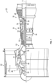
- FIG. 1 schematically illustrates a gas turbine engine 20.
- the gas turbine engine 20 is disclosed herein as a two-spool turbofan that generally incorporates a fan section 22, a compressor section 24, a combustor section 26 and a turbine section 28.
- Alternative engines might include other systems or features.
- the fan section 22 drives air along a bypass flow path B in a bypass duct, while the compressor section 24 drives air along a core flow path C for compression and communication into the combustor section 26 then expansion through the turbine section 28.
- FIG. 1 schematically illustrates a gas turbine engine 20.
- the gas turbine engine 20 is disclosed herein as a two-spool turbofan that generally incorporates a fan section 22, a compressor section 24, a combustor section 26 and a turbine section 28.
- Alternative engines might include other systems or features.
- the fan section 22 drives air along a bypass flow path B in a bypass duct
- the compressor section 24 drives air along a core flow path C for compression and communication into the combustor section 26
- the exemplary engine 20 generally includes a low speed spool 30 and a high speed spool 32 mounted for rotation about an engine central longitudinal axis A relative to an engine static structure 36 via several bearing systems 38. It should be understood that various bearing systems 38 at various locations may alternatively or additionally be provided, and the location of bearing systems 38 may be varied as appropriate to the application.
- the low speed spool 30 generally includes an inner shaft 40 that interconnects a fan 42, a low pressure compressor 44 and a low pressure turbine 46.
- the inner shaft 40 is connected to the fan 42 through a speed change mechanism, which in exemplary gas turbine engine 20 is illustrated as a geared architecture 48 to drive the fan 42 at a lower speed than the low speed spool 30.
- the high speed spool 32 includes an outer shaft 50 that interconnects a high pressure compressor 52 and high pressure turbine 54.
- a combustor 56 is arranged in exemplary gas turbine 20 between the high pressure compressor 52 and the high pressure turbine 54.
- An engine static structure 36 is arranged generally between the high pressure turbine 54 and the low pressure turbine 46.
- the engine static structure 36 further supports bearing systems 38 in the turbine section 28.
- the inner shaft 40 and the outer shaft 50 are concentric and rotate via bearing systems 38 about the engine central longitudinal axis A which is collinear with their longitudinal axes.
- each of the positions of the fan section 22, compressor section 24, combustor section 26, turbine section 28, and fan drive gear system 48 may be varied.
- gear system 48 may be located aft of combustor section 26 or even aft of turbine section 28, and fan section 22 may be positioned forward or aft of the location of gear system 48.
- the engine 20 in one example is a high-bypass geared aircraft engine.
- the engine 20 bypass ratio is greater than about six (6), with an example embodiment being greater than about ten (10)
- the geared architecture 48 is an epicyclic gear train, such as a planetary gear system or other gear system, with a gear reduction ratio of greater than about 2.3 and the low pressure turbine 46 has a pressure ratio that is greater than about five.
- the engine 20 bypass ratio is greater than about ten (10:1)
- the fan diameter is significantly larger than that of the low pressure compressor 44
- the low pressure turbine 46 has a pressure ratio that is greater than about five (5:1).
- Low pressure turbine 46 pressure ratio is pressure measured prior to inlet of low pressure turbine 46 as related to the pressure at the outlet of the low pressure turbine 46 prior to an exhaust nozzle.
- the geared architecture 48 may be an epicycle gear train, such as a planetary gear system or other gear system, with a gear reduction ratio of greater than about 2.3: 1. It should be understood, however, that the above parameters are only exemplary of one embodiment of a geared architecture engine and that the present disclosure is applicable to other gas turbine engines including direct drive turbofans.
- the fan section 22 of the engine 20 is designed for a particular flight condition--typically cruise at about 0.8Mach and about 35,000 feet (10,688 meters).
- 'TSFC' Thrust Specific Fuel Consumption
- Low fan pressure ratio is the pressure ratio across the fan blade alone, without a Fan Exit Guide Vane (“FEGV”) system.
- the low fan pressure ratio as disclosed herein according to one non-limiting embodiment is less than about 1.45.
- the "Low corrected fan tip speed” as disclosed herein according to one non-limiting embodiment is less than about 1150 ft/second (350.5 m/sec).
- the high pressure compressor 52 includes a high pressure compressor rotor 60 located at and rotatable about the engine central longitudinal axis A and a stator 62 located radially outboard of the rotor 60 with respect to the engine central longitudinal axis A.
- a seal arrangement is positioned between the rotating rotor 60 and the rotationally fixed stator 62 to prevent leakage along the flowpath of the high pressure compressor 52.
- the seal arrangement is defined by a two or more knife edges 64 extending radially outwardly from a rotor body 66 of the rotor 60 and circumferentially about the engine central longitudinal axis A.
- the knife edges 64 as illustrated in FIG. 3 , are axially spaced apart by a knife edge spacing 68.
- the knife edges 64 have a radial height 70 greater than an axial thickness 72.
- the knife edges 64 are configured to interact with an inner airseal 74 installed at a radially inner platform 76 of the stator 62.
- the inner airseal 74 includes an abradable seal element 78 defining a radially inner extent of the inner airseal 74, which defines a seal interface with the knife edges 64.
- the abradable seal element 78 is installed in a seal carrier 80, which is installed into the inner platform 76 by, for example, a seal carrier hook 82 engaged with an inner platform hook 84.
- a sensor 86 is installed to the stator 62, and in particular to the inner airseal 74, with the sensor 86 including a sensor body 88 being configured to measure a distance between the sensor body 88 and the rotor body 66 between the knife edges 64, which is indicative of a radial distance between the inner airseal 74 and the rotor body 66.
- the sensor 86 is a capacitance sensor, but one skilled in the art will recognize that other types of sensors 86 may be utilized.
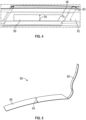
- the sensor body 88 is installed to a radially inner carrier surface 90 of the seal carrier 80, so the sensor body 88 resides, as shown in FIG. 4 , in a trench 92 formed in the seal element 78.
- the sensor body 88 is axially positioned so that an entire axial width 94 of the sensor body 88 is located in the axial knife edge spacing 68 between axially-adj acent knife edges 64. Further, the sensor body 88 is sized and positioned such that even with anticipated axial variation in the knife edge 64 position, the axial width 94 is between the axially adjacent knife edges 64.
- the sensor body 88 is, in a free state, substantially elongated and flat and planar, and thin, in the range of 0.005" to .020" (about 0.13 mm to 0.51 mm) in thickness, resulting in flexibility such that the sensor body 88 can be bent to conform to a shape of the trench 92.
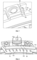
- a signal lead 96 such as an electrical of fiber optic lead, extends from the sensor body 88 and out of the stator 62 as illustrated in FIG. 6 , 7 and 8 . As shown in FIG.
- the signal lead 96 extends through an inner platform opening 98 in the inner platform 76 and extends along a vane surface 100 of a stator vane 102 toward an outer platform 104 of the stator 62.
- the signal lead 96 is fixed to the vane surface 100 by, for example, a glue or other adhesive to stabilize the position of the signal lead 96 and to minimize the obstruction of the signal lead 96 into the flowpath.
- the signal lead 96 extends through an outer platform opening 106 in the outer platform 104 to a back surface 108 of the outer platform 104.
- the signal lead 96 may be further routed along the back surface 108, and through other structure of the stator 62 such as a doghouse 110 and out of the gas turbine engine 20 through a casing (not shown) located radially outboard of the outer platform 104.
- stator 62, the inner airseal 74 and the sensor 86 define a stator assembly, which may be pre-fabricated prior to installation into the gas turbine engine 20. This allows for customization of the stator assembly regarding placement or nonplacement of the sensor 86, and streamlines and improves efficiency of assembly of the gas turbine engine 20.
- the senor 86 is configured for operation in temperatures less than 500 degrees Fahrenheit, but one skilled in the art will appreciate that in some embodiments sensors 86 with other temperature capabilities may be used.
- the sensor 86 is a "wand" sensor 86, which is capacitance based and is made from, for example, printed Kapton ® and thin copper traces. The copper is arranged such that it makes up a center conductor and a guard, which mimics a traditional metallic capacitance-based proximity probe.
- the Kapton ® is the electrical insulator keeping both the center conductor and guard insulated from the ground plane.
- a sensor 86 with a relatively small signal lead 96, allows for the egress out of a component to an area where a standard coaxial cable can be attached thereto.
- the coaxial cable can then be used with traditional signal conditioning. If the sensor 86 is designed to fit into-and be built into-the stator 62, the impact to the system can be minimized.
- the thickness of the sensor 86 allows the sensor body 88 and the signal lead 96 to be bent and formed to fit the surfaces of the stator 62, thereby minimizing the aerodynamic impact to the system.
Landscapes
- Engineering & Computer Science (AREA)
- Mechanical Engineering (AREA)
- General Engineering & Computer Science (AREA)
- Physics & Mathematics (AREA)
- General Physics & Mathematics (AREA)
- Turbine Rotor Nozzle Sealing (AREA)
Applications Claiming Priority (1)
| Application Number | Priority Date | Filing Date | Title |
|---|---|---|---|
| US18/464,792 US20250084770A1 (en) | 2023-09-11 | 2023-09-11 | Proximity measurement between seal elements of a gas turbine engine |
Publications (1)
| Publication Number | Publication Date |
|---|---|
| EP4520926A1 true EP4520926A1 (de) | 2025-03-12 |
Family
ID=91924421
Family Applications (1)
| Application Number | Title | Priority Date | Filing Date |
|---|---|---|---|
| EP24188107.7A Pending EP4520926A1 (de) | 2023-09-11 | 2024-07-11 | Spalt-messung zwischen dichtelementen eines gasturbinenmotors |
Country Status (2)
| Country | Link |
|---|---|
| US (1) | US20250084770A1 (de) |
| EP (1) | EP4520926A1 (de) |
Citations (3)
| Publication number | Priority date | Publication date | Assignee | Title |
|---|---|---|---|---|
| EP1031702B1 (de) * | 1997-12-08 | 2003-09-24 | Mitsubishi Heavy Industries, Ltd. | Automatische Regelvorrichtung für das Statorschaufelspiel einer Gasturbine |
| US20190078869A1 (en) * | 2017-09-12 | 2019-03-14 | United Technologies Corporation | Low profile embedded blade tip clearance sensor |
| US20190186285A1 (en) * | 2017-12-19 | 2019-06-20 | United Technologies Corporation | Capacitance based wear indicator |
Family Cites Families (7)
| Publication number | Priority date | Publication date | Assignee | Title |
|---|---|---|---|---|
| US6903541B2 (en) * | 2001-05-25 | 2005-06-07 | Tyco Electronics Corporation | Film-based microwave and millimeter-wave circuits and sensors |
| US8344741B2 (en) * | 2008-10-16 | 2013-01-01 | General Electric Company | Systems, methods, and apparatus for monitoring clearance in a rotary machine |
| FR2971020B1 (fr) * | 2011-01-28 | 2013-02-08 | Snecma | Soufflante ou compresseur de turbomachine |
| US10240909B2 (en) * | 2016-10-17 | 2019-03-26 | The Boeing Company | Three-dimensional gap measurement systems and methods |
| US11686577B2 (en) * | 2018-09-20 | 2023-06-27 | Raytheon Technologies Corporation | Anti-rotation method for angled face cap probe |
| US11156455B2 (en) * | 2018-09-26 | 2021-10-26 | General Electric Company | System and method for measuring clearance gaps between rotating and stationary components of a turbomachine |
| US11635750B2 (en) * | 2019-10-30 | 2023-04-25 | General Electric Company | System and method for removably inserting a sensor assembly into a compressor casing |
-
2023
- 2023-09-11 US US18/464,792 patent/US20250084770A1/en active Pending
-
2024
- 2024-07-11 EP EP24188107.7A patent/EP4520926A1/de active Pending
Patent Citations (3)
| Publication number | Priority date | Publication date | Assignee | Title |
|---|---|---|---|---|
| EP1031702B1 (de) * | 1997-12-08 | 2003-09-24 | Mitsubishi Heavy Industries, Ltd. | Automatische Regelvorrichtung für das Statorschaufelspiel einer Gasturbine |
| US20190078869A1 (en) * | 2017-09-12 | 2019-03-14 | United Technologies Corporation | Low profile embedded blade tip clearance sensor |
| US20190186285A1 (en) * | 2017-12-19 | 2019-06-20 | United Technologies Corporation | Capacitance based wear indicator |
Also Published As
| Publication number | Publication date |
|---|---|
| US20250084770A1 (en) | 2025-03-13 |
Similar Documents
| Publication | Publication Date | Title |
|---|---|---|
| EP3454033B1 (de) | Elektrischer axialverschiebungs-verschleissanzeigesensor bei nahezu vollem reifen | |
| EP3660281B1 (de) | Verschleissüberwachungssystem, gasturbinentriebwerk und verfahren zum herstellen eines verschleissüberwachungssystems | |
| EP3760838B1 (de) | Verstellbares schaufelsystem von gasturbinenmotoren und verfahren | |
| EP3789588B1 (de) | Hydrostatische dichtung ausgerichtet mit der rotordrehrichtung | |
| EP3789589B1 (de) | Hydrostatische dichtung | |
| EP3366889B1 (de) | Sonde einer gasturbinen-gebläsehülle und verfahren | |
| EP3744951B1 (de) | Winkelmessung einer leitschaufel | |
| EP3772570A1 (de) | Hydrostatische dichtung mit verlängertem trägerarm | |
| EP3517738B1 (de) | Schaufelaussendeckband für ein gasturbinentriebwerk | |
| EP3739171A2 (de) | Vordere leitschaufelschiene für eine gasturbinentriebwerksanordnung | |
| EP4520926A1 (de) | Spalt-messung zwischen dichtelementen eines gasturbinenmotors | |
| EP3569821B1 (de) | Gasturbinentriebwerkstatoranordnung mit einer verbindung mit anderen bauteilen, die leckage reduziert | |
| EP3816466B1 (de) | Drahtlose in-situ-überwachung von motorlagern | |
| EP3477061B1 (de) | Umlaufende spaltdichtung für statorsegment | |
| EP3611358B1 (de) | Entlüftungsventilbetätigungssystem | |
| EP4556684A1 (de) | Schieberdichtung für gasturbinenmotor | |
| EP4524370A1 (de) | Verdrehsicherungsfunktion für die instrumentierung eines gasturbinenmotors | |
| EP4332353A1 (de) | Thermische konditionierung eines flansches mit sekundärströmung | |
| EP3428404B1 (de) | Leitschaufelanordnung für einen gasturbinenmotor | |
| EP4372208A1 (de) | Dichtung für gasturbinenmotor | |
| WO2014035621A1 (en) | Blade outer air seal | |
| EP3859125B1 (de) | Gasturbinenmotor mit einem dichtungselement | |
| EP3550113A2 (de) | Gasturbinenmotor mit freitragenden statoren mit dichtungselementen |
Legal Events
| Date | Code | Title | Description |
|---|---|---|---|
| PUAI | Public reference made under article 153(3) epc to a published international application that has entered the european phase |
Free format text: ORIGINAL CODE: 0009012 |
|
| STAA | Information on the status of an ep patent application or granted ep patent |
Free format text: STATUS: THE APPLICATION HAS BEEN PUBLISHED |
|
| AK | Designated contracting states |
Kind code of ref document: A1 Designated state(s): AL AT BE BG CH CY CZ DE DK EE ES FI FR GB GR HR HU IE IS IT LI LT LU LV MC ME MK MT NL NO PL PT RO RS SE SI SK SM TR |
|
| STAA | Information on the status of an ep patent application or granted ep patent |
Free format text: STATUS: REQUEST FOR EXAMINATION WAS MADE |
|
| 17P | Request for examination filed |
Effective date: 20250912 |