EP4520946A2 - Ensemble tuyère d'échappement pour système de propulsion d'aéronef - Google Patents
Ensemble tuyère d'échappement pour système de propulsion d'aéronef Download PDFInfo
- Publication number
- EP4520946A2 EP4520946A2 EP24199799.8A EP24199799A EP4520946A2 EP 4520946 A2 EP4520946 A2 EP 4520946A2 EP 24199799 A EP24199799 A EP 24199799A EP 4520946 A2 EP4520946 A2 EP 4520946A2
- Authority
- EP
- European Patent Office
- Prior art keywords
- nozzle
- skin
- fairing
- seal
- fairing skin
- Prior art date
- Legal status (The legal status is an assumption and is not a legal conclusion. Google has not performed a legal analysis and makes no representation as to the accuracy of the status listed.)
- Pending
Links
Images






Classifications
-
- F—MECHANICAL ENGINEERING; LIGHTING; HEATING; WEAPONS; BLASTING
- F02—COMBUSTION ENGINES; HOT-GAS OR COMBUSTION-PRODUCT ENGINE PLANTS
- F02K—JET-PROPULSION PLANTS
- F02K1/00—Plants characterised by the form or arrangement of the jet pipe or nozzle; Jet pipes or nozzles peculiar thereto
- F02K1/38—Introducing air inside the jet
- F02K1/386—Introducing air inside the jet mixing devices in the jet pipe, e.g. for mixing primary and secondary flow
-
- B—PERFORMING OPERATIONS; TRANSPORTING
- B64—AIRCRAFT; AVIATION; COSMONAUTICS
- B64D—EQUIPMENT FOR FITTING IN OR TO AIRCRAFT; FLIGHT SUITS; PARACHUTES; ARRANGEMENT OR MOUNTING OF POWER PLANTS OR PROPULSION TRANSMISSIONS IN AIRCRAFT
- B64D33/00—Arrangement in aircraft of power plant parts or auxiliaries not otherwise provided for
- B64D33/04—Arrangement in aircraft of power plant parts or auxiliaries not otherwise provided for of exhaust outlets or jet pipes
-
- F—MECHANICAL ENGINEERING; LIGHTING; HEATING; WEAPONS; BLASTING
- F02—COMBUSTION ENGINES; HOT-GAS OR COMBUSTION-PRODUCT ENGINE PLANTS
- F02C—GAS-TURBINE PLANTS; AIR INTAKES FOR JET-PROPULSION PLANTS; CONTROLLING FUEL SUPPLY IN AIR-BREATHING JET-PROPULSION PLANTS
- F02C7/00—Features, components parts, details or accessories, not provided for in, or of interest apart form groups F02C1/00 - F02C6/00; Air intakes for jet-propulsion plants
- F02C7/24—Heat or noise insulation
- F02C7/25—Fire protection or prevention
-
- F—MECHANICAL ENGINEERING; LIGHTING; HEATING; WEAPONS; BLASTING
- F02—COMBUSTION ENGINES; HOT-GAS OR COMBUSTION-PRODUCT ENGINE PLANTS
- F02K—JET-PROPULSION PLANTS
- F02K1/00—Plants characterised by the form or arrangement of the jet pipe or nozzle; Jet pipes or nozzles peculiar thereto
- F02K1/46—Nozzles having means for adding air to the jet or for augmenting the mixing region between the jet and the ambient air, e.g. for silencing
- F02K1/48—Corrugated nozzles
-
- F—MECHANICAL ENGINEERING; LIGHTING; HEATING; WEAPONS; BLASTING
- F02—COMBUSTION ENGINES; HOT-GAS OR COMBUSTION-PRODUCT ENGINE PLANTS
- F02K—JET-PROPULSION PLANTS
- F02K1/00—Plants characterised by the form or arrangement of the jet pipe or nozzle; Jet pipes or nozzles peculiar thereto
- F02K1/78—Other construction of jet pipes
- F02K1/80—Couplings or connections
- F02K1/805—Sealing devices therefor, e.g. for movable parts of jet pipes or nozzle flaps
-
- F—MECHANICAL ENGINEERING; LIGHTING; HEATING; WEAPONS; BLASTING
- F02—COMBUSTION ENGINES; HOT-GAS OR COMBUSTION-PRODUCT ENGINE PLANTS
- F02K—JET-PROPULSION PLANTS
- F02K1/00—Plants characterised by the form or arrangement of the jet pipe or nozzle; Jet pipes or nozzles peculiar thereto
- F02K1/78—Other construction of jet pipes
- F02K1/82—Jet pipe walls, e.g. liners
- F02K1/827—Sound absorbing structures or liners
-
- F—MECHANICAL ENGINEERING; LIGHTING; HEATING; WEAPONS; BLASTING
- F05—INDEXING SCHEMES RELATING TO ENGINES OR PUMPS IN VARIOUS SUBCLASSES OF CLASSES F01-F04
- F05D—INDEXING SCHEME FOR ASPECTS RELATING TO NON-POSITIVE-DISPLACEMENT MACHINES OR ENGINES, GAS-TURBINES OR JET-PROPULSION PLANTS
- F05D2230/00—Manufacture
- F05D2230/20—Manufacture essentially without removing material
- F05D2230/23—Manufacture essentially without removing material by permanently joining parts together
- F05D2230/232—Manufacture essentially without removing material by permanently joining parts together by welding
-
- F—MECHANICAL ENGINEERING; LIGHTING; HEATING; WEAPONS; BLASTING
- F05—INDEXING SCHEMES RELATING TO ENGINES OR PUMPS IN VARIOUS SUBCLASSES OF CLASSES F01-F04
- F05D—INDEXING SCHEME FOR ASPECTS RELATING TO NON-POSITIVE-DISPLACEMENT MACHINES OR ENGINES, GAS-TURBINES OR JET-PROPULSION PLANTS
- F05D2230/00—Manufacture
- F05D2230/20—Manufacture essentially without removing material
- F05D2230/23—Manufacture essentially without removing material by permanently joining parts together
- F05D2230/232—Manufacture essentially without removing material by permanently joining parts together by welding
- F05D2230/236—Diffusion bonding
-
- F—MECHANICAL ENGINEERING; LIGHTING; HEATING; WEAPONS; BLASTING
- F05—INDEXING SCHEMES RELATING TO ENGINES OR PUMPS IN VARIOUS SUBCLASSES OF CLASSES F01-F04
- F05D—INDEXING SCHEME FOR ASPECTS RELATING TO NON-POSITIVE-DISPLACEMENT MACHINES OR ENGINES, GAS-TURBINES OR JET-PROPULSION PLANTS
- F05D2240/00—Components
- F05D2240/55—Seals
-
- F—MECHANICAL ENGINEERING; LIGHTING; HEATING; WEAPONS; BLASTING
- F05—INDEXING SCHEMES RELATING TO ENGINES OR PUMPS IN VARIOUS SUBCLASSES OF CLASSES F01-F04
- F05D—INDEXING SCHEME FOR ASPECTS RELATING TO NON-POSITIVE-DISPLACEMENT MACHINES OR ENGINES, GAS-TURBINES OR JET-PROPULSION PLANTS
- F05D2250/00—Geometry
- F05D2250/10—Two-dimensional
- F05D2250/11—Two-dimensional triangular
-
- F—MECHANICAL ENGINEERING; LIGHTING; HEATING; WEAPONS; BLASTING
- F05—INDEXING SCHEMES RELATING TO ENGINES OR PUMPS IN VARIOUS SUBCLASSES OF CLASSES F01-F04
- F05D—INDEXING SCHEME FOR ASPECTS RELATING TO NON-POSITIVE-DISPLACEMENT MACHINES OR ENGINES, GAS-TURBINES OR JET-PROPULSION PLANTS
- F05D2250/00—Geometry
- F05D2250/20—Three-dimensional
- F05D2250/28—Three-dimensional patterned
- F05D2250/283—Three-dimensional patterned honeycomb
-
- F—MECHANICAL ENGINEERING; LIGHTING; HEATING; WEAPONS; BLASTING
- F05—INDEXING SCHEMES RELATING TO ENGINES OR PUMPS IN VARIOUS SUBCLASSES OF CLASSES F01-F04
- F05D—INDEXING SCHEME FOR ASPECTS RELATING TO NON-POSITIVE-DISPLACEMENT MACHINES OR ENGINES, GAS-TURBINES OR JET-PROPULSION PLANTS
- F05D2260/00—Function
- F05D2260/96—Preventing, counteracting or reducing vibration or noise
Definitions
- This disclosure relates generally to an aircraft propulsion system and, more particularly, to an exhaust nozzle assembly for the aircraft propulsion system.
- An aircraft propulsion system directs combustion products through an exhaust outlet between an exhaust nozzle and an exhaust center body. Sounds waves (e.g., noise) generated during propulsion system operation may be reduced using a chevron ring at the exhaust outlet.
- Sounds waves e.g., noise
- chevron rings e.g., chevron rings
- Various exhaust nozzle assemblies with chevron rings are known in the art. While these known exhaust nozzle assemblies have various benefits, there is still room in the art for improvement.
- an apparatus for an aircraft propulsion system.
- This apparatus includes an exhaust nozzle, a fire seal, a plurality of studs and a plurality of nuts.
- the exhaust nozzle includes a chevron ring and a fairing skin.
- the chevron ring extends axially along an axis to and forms a downstream trailing edge of the exhaust nozzle.
- the chevron ring includes a plurality of chevrons arranged circumferentially about the axis along the downstream trailing edge of the exhaust nozzle.
- the fairing skin is disposed radially outboard of and is attached to the chevron ring.
- the fairing skin projects axially along the axis away from the chevron ring, in an axial upstream direction axially away from the downstream trailing edge of the exhaust nozzle, to an upstream distal end of the fairing skin.
- the fire seal is disposed radially outboard of the fairing skin.
- the fire seal axially and circumferentially overlaps the fairing skin.
- the fire seal includes a plurality of seal apertures.
- the studs are arranged circumferentially about the axis and are mounted to the fairing skin.
- Each of the studs projects longitudinally out from the fairing skin, through a respective one of the seal apertures, to a respective distal stud end.
- Each of the nuts is threaded onto a respective one of the studs at the respective distal stud end.
- the fire seal is clamped radially between the fairing skin and the nuts.
- an apparatus for an aircraft propulsion system.
- This apparatus includes an exhaust nozzle, a fire seal, a plurality of studs and a plurality of nuts.
- the exhaust nozzle includes a nozzle wall, a nozzle ring and a fairing skin.
- the nozzle wall extends axially along an axis from an upstream end of the nozzle wall to a downstream end of the nozzle wall.
- the nozzle wall extends circumferentially around the axis.
- An inner side of the nozzle wall forms an outer peripheral boundary of a propulsion system flowpath axially along the nozzle wall.
- the nozzle ring forms a downstream trailing edge of the exhaust nozzle.
- the nozzle ring projects axially out from the downstream end of the nozzle wall to the downstream trailing edge of the exhaust nozzle to form another outer peripheral boundary of the propulsion system flowpath axially along the nozzle ring.
- the fairing skin is disposed radially outboard of and is attached to the nozzle ring.
- the fairing skin projects axially along the axis away from the nozzle ring, in an axial upstream direction axially away from the downstream trailing edge of the exhaust nozzle, to an upstream distal end of the fairing skin.
- the fire seal is disposed radially outboard of the fairing skin.
- the fire seal axially and circumferentially overlaps the fairing skin.
- the studs are arranged circumferentially about the axis and mounted to the fairing skin.
- Each of the studs projects longitudinally out from the fairing skin, through the fire seal, to a respective distal stud end.
- Each of the nuts is threaded onto a respective one of the studs at the respective distal stud end.
- the fire seal is clamped radially between the fairing skin and the nuts.
- a manufacturing method for an aircraft propulsion system includes: arranging a fairing skin with a chevron ring, the fairing skin disposed radially outboard of the chevron ring, the chevron ring extending axially along an axis to and forming a downstream trailing edge of an exhaust nozzle, and the chevron ring including a ring base and a plurality of chevrons arranged circumferentially about the axis along the downstream trailing edge of the exhaust nozzle; attaching the fairing skin to the ring base; arranging a fire seal with the fairing skin; and attaching the fire seal to the fairing skin using a plurality of studs and a plurality of nuts.
- the studs are arranged circumferentially about the axis and mounted to the fairing skin.
- Each of the studs projects longitudinally out from the fairing skin, through the fire seal, to a respective distal stud end.
- Each of the nuts is threaded onto a respective one of the studs at the respective distal stud end. The fire seal is clamped radially between the fairing skin and the nuts.
- the apparatus may also include a plurality of stud plates mounted to the fairing skin at an inner side of the fairing skin.
- Each of the studs may be fixed to a respective one of the stud plates.
- Each of the studs may project longitudinally out from the respective one of the stud plates, through a respective one of a plurality of skin apertures in the fairing skin and the respective one of the seal apertures, to the respective distal stud end.
- Each of the stud plates may be riveted to the fairing skin.
- Each of the stud plates may be mechanically fastened to the fairing skin.
- the apparatus may also include a stud plate mounted to the fairing skin at an inner side of the fairing skin.
- Each of the studs may be fixed to the stud plate.
- Each of the studs may project longitudinally out from the stud plate, through a respective one of a plurality of skin apertures in the fairing skin and the respective one of the seal apertures, to the respective distal stud end.
- Each of the stud plates may be riveted to the fairing skin.
- Each of the stud plates may be mechanically fastened to the fairing skin.
- the fire seal may include a seal base and a spring seal.
- the seal base may be mounted to the fairing skin by the studs and the nuts.
- the seal spring may project axially out from the seal base, in the axial upstream direction, to a distal end of the fire seal.
- the seal spring may be radially spaced from the fairing skin by an air gap axially from the seal base to the distal end of the fire seal.
- the fire seal may be formed by a stack of axially and circumferentially overlapping leaf spring seals.
- the apparatus may also include an inner support member clamped radially between the seal base and the fairing skin.
- Each of the studs may project longitudinally through a respective one of an inner member apertures in the inner support member.
- the apparatus may also include an outer support member.
- the seal base may be clamped radially between the outer support member and the inner support member.
- Each of the studs may project longitudinally through a respective one of a plurality of outer member apertures in the outer support member.
- the apparatus may also include an outer support member.
- the seal base may be clamped radially between the outer support member and the fairing skin.
- Each of the studs may project longitudinally through a respective one of a plurality of outer member apertures in the outer support member.
- the exhaust nozzle may also include a nozzle wall extending axially along the axis from an upstream end of the nozzle wall to a downstream end of the nozzle wall.
- the nozzle wall may extend circumferentially around the axis.
- An inner side of the nozzle wall may form an outer peripheral boundary of a propulsion system flowpath axially along the nozzle wall to the chevron ring.
- the chevron ring may be attached to the nozzle wall at the downstream end of the nozzle wall.
- the fairing skin may axially and circumferentially overlap the nozzle wall.
- the fairing skin may be radially spaced from the nozzle wall by an air gap.
- the nozzle wall may include an inner skin, an outer skin and a cellular core radially between and bonded to the inner skin and the outer skin.
- the inner skin may form the inner side of the nozzle wall.
- the nozzle wall may be configured as or otherwise include an acoustic panel.
- the apparatus may also include an exhaust center body and a flowpath exhaust.
- the exhaust nozzle may be spaced radially outboard from and circumscribe the exhaust center body.
- the flowpath exhaust may be formed by and extend radially between the exhaust center body and the chevron ring.
- the apparatus may also include an engine core and a propulsion system flowpath.
- the engine core may include a compressor section, a combustor section and a turbine section.
- the propulsion system flowpath may extend sequentially through the compressor section, the combustor section and the turbine section to an exhaust.
- the exhaust nozzle may form a radial outer peripheral boundary of the exhaust.
- the present disclosure may include any one or more of the individual features disclosed above and/or below alone or in any combination thereof.
- FIG. 1 illustrates an aircraft propulsion system 20 for an aircraft.
- the aircraft may be an airplane, a drone (e.g., an unmanned aerial vehicle (UAV)) or any other manned or unmanned aerial vehicle or system.
- the aircraft propulsion system 20 of FIG. 1 includes a gas turbine engine 22 and a nacelle 24.
- the turbine engine 22 is configured to power operation of the aircraft propulsion system 20.
- the turbine engine 22 is generally described below as a turbofan engine such as a high-bypass turbofan engine.
- the turbine engine 22 of FIG. 1 includes a fan section 26, a compressor section 27, a combustor section 28 and a turbine section 29.
- the compressor section 27 may include a low pressure compressor (LPC) section 27A and a high pressure compressor (HPC) section 27B.
- the turbine section 29 may include a high pressure turbine (HPT) section 29A and a low pressure turbine (LPT) section 29B.
- LPC low pressure compressor
- HPC high pressure compressor
- LPT high pressure turbine
- LPT low pressure turbine
- the aircraft propulsion system 20 extends axially along an axis 30 from a forward, upstream end of the aircraft propulsion system 20 to an aft, downstream end of the aircraft propulsion system 20.
- the engine sections 26-29B of FIG. 1 are arranged sequentially along the axis 30 within a housing 32 of the aircraft propulsion system 20.
- the axis 30 may be a centerline axis of the turbine engine 22, the propulsion system housing 32 and/or, more generally, the aircraft propulsion system 20.
- the axis 30 may also or alternatively be a centerline axis and/or a rotational axis of one or more rotating members of the turbine engine 22.
- the propulsion system housing 32 of FIG. 1 includes an outer housing structure 34 and an inner housing structure 36.
- the outer housing structure 34 includes an outer case 38 (e.g., a fan case, a containment case, etc.) and an outer structure of the nacelle 24 - an outer nacelle structure 40.
- the outer case 38 houses at least the fan section 26.
- the outer nacelle structure 40 houses and provides an aerodynamic cover over the outer case 38.
- the outer nacelle structure 40 also covers a portion of an inner structure of the nacelle 24 - an inner nacelle structure 42.
- the outer nacelle structure 40 of FIG. 1 for example, axially overlaps and extends circumferentially about (e.g., completely around) the inner nacelle structure 42.
- the outer nacelle structure 40 and the inner nacelle structure 42 thereby at least partially or completely form a bypass flowpath 44; e.g., a D-duct, C-duct or O-duct bypass flowpath.
- This bypass flowpath 44 extends axially along the axis 30 within the aircraft propulsion system 20 to a bypass exhaust 46 (e.g., a bypass outlet orifice).
- the bypass flowpath 44 is formed by and extends radially between the outer nacelle structure 40 and the inner nacelle structure 42.
- the inner housing structure 36 includes an inner case 48 (e.g., a core case) and the inner nacelle structure 42, which inner nacelle structure 42 may also be referred to as or include an inner fixed structure.
- the inner case 48 houses one or more of the engine sections 27A-29B, where at least (or only) the engine sections 27A-29B may collectively form a core of the turbine engine 22.
- the inner nacelle structure 42 houses and provides an aerodynamic cover for the inner case 48.
- a downstream / aft portion of the inner housing structure 36 such as, for example, a (e.g., tubular) core exhaust nozzle 50 of the inner nacelle structure 42 also covers at least a portion of an (e.g., conical) exhaust center body 52.
- the inner nacelle structure 42 and its exhaust nozzle 50 axially overlap and extend circumferentially about (e.g., completely around) the exhaust center body 52.
- the exhaust nozzle 50 and the exhaust center body 52 thereby collectively form a downstream / aft portion of a core flowpath 54 (e.g., an annular core flowpath) within the turbine engine 22 and its engine core.
- This core flowpath 54 extends axially within the aircraft propulsion system 20, sequentially through the engine core and its engine sections 27A-29B, to a core exhaust 55 (e.g., an annular core outlet orifice) at and/or towards a downstream / aft end of the aircraft propulsion system 20.
- Each of the engine sections 26-29B of FIG. 1 includes a respective bladed engine rotor 56-60.
- Each of these engine rotors 56-60 includes a plurality of rotor blades arranged circumferentially around and connected to one or more respective rotor disks.
- the fan rotor 56 and the LPC rotor 57 are connected to and driven by the LPT rotor 60 through a low speed shaft 62.
- the HPC rotor 58 is connected to and driven by the HPT rotor 59 through a high speed shaft 64.
- the engine shafts 62 and 64 are rotatably supported by a plurality of bearings (not shown). Each of these bearings is connected to the propulsion system housing 32 by at least one stationary structure such as, for example, an annular support strut.
- the air entering the core flowpath 54 may be referred to as core air.
- the air within the bypass flowpath 44 may be referred to as bypass air.
- the core air is compressed by the LPC rotor 57 and the HPC rotor 58 and directed into a combustion chamber of a combustor in the combustor section 28.
- Fuel is injected into the combustion chamber and mixed with the compressed core air to provide a fuel-air mixture.
- This fuel air mixture is ignited and combustion products thereof flow through and sequentially drive rotation of the HPT rotor 59 and the LPT rotor 60.
- the rotation of the HPT rotor 59 and the LPT rotor 60 respectively drive rotation of the HPC rotor 58 and the LPC rotor 57 and, thus, compression of the air received from an airflow inlet into the engine core.
- the rotation of the LPT rotor 60 also drives rotation of the fan rotor 56. This rotation of the fan rotor 56 propels bypass air through the bypass flowpath 44 and out of the aircraft propulsion system 20 through the bypass exhaust 46.
- the propulsion of the bypass air may account for a majority of thrust generated by the turbine engine 22.
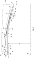
- FIG. 2 illustrates an exhaust nozzle assembly 68 for the aircraft propulsion system 20.
- This exhaust nozzle assembly 68 includes the exhaust nozzle 50 and one or more fire seals; e.g., an axial forward, upstream fire seal 70 and an axial aft, downstream fire seal 72.
- the exhaust nozzle 50 extends axially along the axis 30 from an axial forward, upstream end 74 of the exhaust nozzle 50 to an axial aft, downstream trailing edge 76 of the exhaust nozzle 50.
- the exhaust nozzle 50 of FIG. 2 includes an exhaust nozzle wall 78, an exhaust nozzle ring 80 and an exhaust nozzle fairing skin 82. Referring to FIG.
- the exhaust nozzle 50 and each of its members 78, 80 and 82 extend circumferentially about (e.g., completely around) the axis 30.
- the exhaust nozzle 50 and its members 78, 80 and 82 may thereby each have a full-hoop (e.g., tubular and/or annular) geometry around the axis 30.
- the nozzle wall 78 extends axially along the axis 30 from the nozzle upstream end 74 to an axial aft, downstream end 84 of the nozzle wall 78; see also FIG. 6 .
- the nozzle upstream end 74 of FIG. 2 is also an axial forward, upstream end of the nozzle wall 78.
- the nozzle wall 78 extends radially from a radial inner side 86 of the exhaust nozzle 50 and its nozzle wall 78 to a radial outer side 88 of the nozzle wall 78.
- the nozzle wall 78 of FIG. 2 includes a structured panel (e.g., an acoustic panel) and an exhaust nozzle mounting structure 90.
- FIGS. 4 and 5 includes a fluid permeable (e.g., perforated) radial inner skin 92, a fluid impermeable (e.g., non-perforated) radial outer skin 94 and a cellular core 96; see also FIGS. 4 and 5 .
- a fluid permeable (e.g., perforated) radial inner skin 92 includes a fluid permeable (e.g., perforated) radial inner skin 92, a fluid impermeable (e.g., non-perforated) radial outer skin 94 and a cellular core 96; see also FIGS. 4 and 5 .
- the nozzle inner skin 92 may be constructed from a relatively thin sheet or layer of material; e.g., sheet metal.
- the nozzle inner skin 92 extends axially along the axis 30 from the nozzle upstream end 74 to (or about) the wall downstream end 84.
- the nozzle inner skin 92 projects axially (e.g., slightly) past the wall downstream end 84 to axially overlap the nozzle ring 80 as described below in further detail.
- the nozzle inner skin 92 extends circumferentially about (e.g., completely around) the axis 30.
- the nozzle inner skin 92 may thereby form an axial forward, upstream section of the nozzle inner side 86 from the nozzle upstream end 74 to the nozzle ring 80.
- This nozzle inner skin 92 and its inner side upstream section also form a radial outer peripheral boundary of the core flowpath 54 axially along the exhaust nozzle 50 and its nozzle wall 78 from the nozzle upstream end 74 to the nozzle ring 80.
- the nozzle inner skin 92 includes a plurality of inner skin perforations 98; e.g., apertures such as through-holes. Each of these inner skin perforations 98 extends (e.g., radially) through the nozzle inner skin 92 thereby piercing the nozzle inner side 86 along the core flowpath 54.
- the nozzle outer skin 94 may be constructed from a relatively thin sheet or layer of material; e.g., sheet metal.
- the nozzle outer skin 94 of FIG. 2 extends axially along the axis 30 from about the nozzle upstream end 74 to (or about) the wall downstream end 84.
- the nozzle outer skin 94 projects axially (e.g., slightly) past the wall downstream end 84 to axially overlap the nozzle ring 80 as described below in further detail.
- the nozzle outer skin 94 extends circumferentially about (e.g., completely around) the axis 30.
- the nozzle outer skin 94 thereby axially overlaps and extends circumferentially about (e.g., circumscribes) the nozzle inner skin 92.
- the nozzle outer skin 94 of FIG. 4 is configured as a continuous, uninterrupted and/or non-perforated skin; e.g., a skin without any perforations at least along internal cavities of the nozzle wall 78.
- the nozzle core 96 is disposed radially between the nozzle inner skin 92 and the nozzle outer skin 94.
- the nozzle core 96 of FIG. 4 has a radial thickness 100 that extends radially from the nozzle inner skin 92 to the nozzle outer skin 94.
- a radial inner side of the nozzle core 96 may be radially abutted against or otherwise engage the nozzle inner skin 92.
- a radial outer side of the nozzle core 96 is radially abutted against or otherwise engage the nozzle outer skin 94.
- the nozzle core 96 extends axially along the axis 30 from the nozzle mounting structure 90 to the nozzle ring 80.
- the nozzle core 96 extends circumferentially about (e.g., completely around) the axis 30.
- the core thickness 100 of FIG. 4 may be substantially larger than a radial thickness 102 of the nozzle inner skin 92 and/or a radial thickness 104 of the nozzle outer skin 94.
- the core thickness 100 may be at least two to ten times (2-10x), or more, larger than the inner skin thickness 102 and/or the outer skin thickness 104.
- the nozzle wall 78 of the present disclosure is not limited to such an exemplary dimensional relationship and the core thickness 100 may vary based on sound attenuation requirements, space requirements, etc.
- each core cavity 106 of FIG. 4 extends radially within / through the nozzle core 96 from the nozzle inner skin 92 to the nozzle outer skin 94.
- One or more or all of the core cavities 106 may thereby each overlap and be fluidly coupled with a respective set of one or more of the inner skin perforations 98.
- each of the core cavities 106 has a cross-sectional geometry (e.g., shape, size, etc.) when viewed in a reference plane; e.g., a plane perpendicular to a centerline 110 of the respective core cavity 106.
- This cavity cross-sectional geometry may have a polygonal shape such as a hexagonal shape.
- various other types of cellular cores including various other types of honeycomb cores are known in the art, and the present disclosure is not limited to any particular ones thereof.
- the nozzle mounting structure 90 is configured to support the exhaust nozzle 50 at the nozzle upstream end 74.
- the nozzle mounting structure 90 is also configured to mount the exhaust nozzle 50 and its members to a component of the inner housing structure 36 (see FIG. 1 ) such as a turbine exhaust case (TEC).
- TEC turbine exhaust case
- the nozzle mounting structure 90 extends axially along the axis 30 in an axial forward, upstream direction (e.g., axially away from nozzle trailing edge 76) from the nozzle core 96 to the nozzle upstream end 74.
- the nozzle mounting structure 90 of FIG. 2 includes a forward, upstream closeout ring 112, an extension arm 114 and an attach flange 116.
- the nozzle mounting structure 90 and each of its members 112, 114 and 116 extend circumferentially about (e.g., completely around) the axis 30.
- the closeout ring 112 is axially abutted against an axial forward, upstream end 118 of the nozzle core 96.
- the closeout ring 112 is disposed and extends radially between the nozzle inner skin 92 and the nozzle outer skin 94.
- the closeout ring 112 is also bonded (e.g., diffusion bonded) or otherwise attached to the nozzle inner skin 92 and the nozzle outer skin 94.
- the extension arm 114 projects axially along the nozzle inner skin 92 out from the closeout ring 112 to the attach flange 116.
- the extension arm 114 is also bonded (e.g., diffusion bonded) or otherwise attached to the nozzle inner skin 92.
- the attach flange 116 is disposed at the nozzle upstream end 74 and projects radially outward, away from the nozzle inner skin 92 and the extension arm 114, to a radial outer distal end of the attach flange 116.
- the attach flange 116 is also bonded (e.g., diffusion bonded) or otherwise attached to the nozzle inner skin 92.
- the nozzle mounting structure 90 is thereby formed as an integrated part of the nozzle wall 78 along with the nozzle core 96.
- the nozzle mounting structure 90 and its members 112, 114 and 116 axially and circumferentially overlap the nozzle inner skin 92.
- the nozzle outer skin 94 axially and circumferentially overlaps the nozzle mounting structure 90 and its closeout ring 112.
- the present disclosure is not limited to such an exemplary integration of the nozzle mounting structure 90 into the nozzle wall 78.
- the nozzle ring 80 is configured to form the nozzle trailing edge 76.
- the nozzle ring 80 of FIG. 2 extends axially along the axis 30 out form an axial forward, upstream end 120 of the nozzle ring 80 to the nozzle trailing edge 76.
- the nozzle trailing edge 76 of FIG. 2 is also an axial aft, downstream trailing edge of the nozzle ring 80.
- the nozzle ring 80 extends radially from the radial inner side 86 of the exhaust nozzle 50 and its nozzle ring 80 to a radial outer side 122 of the exhaust nozzle 50 and its nozzle ring 80.
- the nozzle ring 80 may thereby form (a) an axial aft, downstream section of the nozzle inner side 86 from the nozzle wall 78 to the nozzle trailing edge 76 and (b) an axial aft, downstream section of the nozzle outer side 122 from the nozzle wall 78 to the nozzle trailing edge 76.
- the nozzle ring 80 and its inner side downstream section also form another radial outer peripheral boundary of the core flowpath 54 axially along the exhaust nozzle 50 and its nozzle ring 80 from the nozzle wall 78 to the nozzle trailing edge 76.
- the nozzle ring 80 may be configured as an exhaust nozzle chevron ring.
- the nozzle ring 80 of FIG. 3 for example, includes a nozzle ring base 124 and one or more chevrons 126.
- the ring base 124 is disposed at the ring upstream end 120.
- the ring base 124 of FIG. 2 extends axially along the axis 30 from the ring upstream end 120 to an axial aft, downstream end 128 of the ring base 124.
- the ring base 124 extends radially between and to the nozzle inner side 86 and the nozzle outer side 122.
- the ring base 124 extends circumferentially about (e.g., completely around) the axis 30; e.g., see also FIG. 3 .
- Each of the recesses 130-132 projects axially in an axial aft, downstream direction (e.g., axially towards the nozzle trailing edge 76) partially into the ring base 124 to an axial end of the respective recess 130-132.
- Each of these recesses 130-132 may extend within the ring base 124 circumferentially about (e.g., completely around) the axis 30.
- Each of the recesses 130-132 may thereby have an annular geometry around the axis 30.
- the chevrons 126 are arranged and may (or may not) be equispaced circumferentially about the axis 30 in an annular or an arcuate array along the nozzle trailing edge 76.
- Each of these chevrons 126 is connected to the ring base 124 at its base downstream end 128 (see FIG. 2 ).
- Each of the chevrons 126 projects axially out from the ring base 124 to a tip 134 of the respective chevron 126 at the nozzle trailing edge 76.
- Each of these chevrons 126 may have a substantially triangular or otherwise tapered geometry when viewed, for example, in a reference plane tangent to the nozzle ring 80 at the respective chevron 126.
- Each of the chevrons 126 of FIG. 3 has a width 136 that extends lateral (e.g., circumferential) between opposing lateral sides 138 of the respective chevron 126.
- This chevron width 136 decreases as the respective chevron 126 extends axially from (or about) the ring base 124 to the respective chevron tip 134, where the chevron sides 138 laterally converge and meet at the chevron tip 134.
- each circumferentially neighboring (e.g., adjacent) pair of the chevrons 126 and their respective circumferential circumferentially neighboring chevron sides 138 may meet and form an inter-chevron trough 140.
- the chevron tips 134, the chevron sides 138 and the inter-chevron troughs 140 may collectively form the nozzle trailing edge 76.
- the nozzle trailing edge 76 of FIG. 3 thereby has an axially undulating (e.g., wavy, sinusoidal, sawtooth, etc.) geometry around the axis 30.
- the nozzle ring 80 of FIGS. 2 and 3 is formed as a monolithic body; e.g., a metal body.
- the ring base 124 and the chevrons 126 may be cast, forged, milled, machined, additively manufactured and/or otherwise formed as a single, unitary body.
- a non-monolithic body includes a plurality of members which are discretely formed and subsequently attached together. The present disclosure, however, is not limited to the foregoing exemplary nozzle ring formation techniques.
- the nozzle ring 80 may be integrated with the nozzle wall 78 at or about the wall downstream end 84.
- the ring base 124 of FIG. 6 is axially abutted against and/or otherwise engaged with the nozzle core 96.
- the nozzle inner skin 92 projects axially in the axial downstream direction away from the nozzle core 96 and into the inner skin recess 130.
- An axial aft, downstream end portion 142 of the nozzle inner skin 92 is disposed (e.g., seated) in the inner skin recess 130 radially against the inner skin land.
- the inner skin end portion 142 thereby extends axially and circumferentially along the nozzle ring 80 and its ring base 124.
- This inner skin end portion 142 is also bonded (e.g., diffusion bonded) to the nozzle ring 80 and its ring base 124.
- the nozzle outer skin 94 projects axially in the axial downstream direction away from the nozzle core 96 and into the outer skin recess 132.
- An axial aft, downstream end portion 144 of the nozzle outer skin 94 is disposed (e.g., seated) in the outer skin recess 132 radially against the outer skin land. The outer skin end portion 144 thereby extends axially and circumferentially along the nozzle ring 80 and its ring base 124.
- This outer skin end portion 144 is also bonded (e.g., diffusion bonded) to the nozzle ring 80 and its ring base 124.
- the nozzle ring 80 and its ring base 124 are disposed radially between the nozzle inner skin 92 and the nozzle outer skin 94.
- the nozzle ring 80 may be connected to the nozzle wall 78 without use of any fasteners; e.g., bolts, rivets, etc.
- the nozzle ring 80 and its ring base 124 may also form an axial aft, downstream closeout for the nozzle wall 78.
- the nozzle ring 80 may be bonded to the nozzle inner skin 92 and the nozzle outer skin 94 concurrently with the nozzle core 96.
- the nozzle ring 80 and its ring base 124 may be tack welded (e.g., resistance tack welded) to the nozzle core 96.
- This tack welded structure may then be arranged with the nozzle inner skin 92 and the nozzle outer skin 94 to facilitate (e.g., concurrent) bonding of the nozzle inner skin 92 and the nozzle outer skin 94 to the nozzle core 96 and the ring base 124.
- the nozzle core 96 may also be diffusion bonded to the nozzle ring 80 and its ring base 124 as well.
- the nozzle inner skin 92 and the nozzle outer skin 94 may each partially axially overlap the nozzle ring 80 and its ring base 124. It is contemplated, however, that the nozzle inner skin 92 and/or the nozzle outer skin 94 may alternatively completely axially overlap the nozzle ring 80.
- the nozzle inner skin 92 of FIG. 7 may extend along an axial extent of the nozzle ring 80 to the nozzle trailing edge 76. With such an arrangement, the exhaust nozzle 50 may be configured with fewer interruptions along its nozzle inner side 86.
- the nozzle fairing skin 82 extends axially along the axis 30 from an axial forward, upstream end 146 of the nozzle fairing skin 82 to an axial aft, downstream end 148 of the nozzle fairing skin 82.
- the nozzle fairing skin 82 extends radially from a radial inner side of the nozzle fairing skin 82 to the radial outer side 122 of the exhaust nozzle 50 and its nozzle fairing skin 82.
- the nozzle fairing skin 82 may thereby form an axial forward, upstream section of the nozzle outer side 122 from the fairing skin upstream end 146 to the nozzle ring 80.
- the nozzle fairing skin 82 may be constructed from a relatively thin sheet or layer of material; e.g., sheet metal.
- the nozzle fairing skin 82 is disposed radially outboard of the nozzle wall 78 and the nozzle ring 80. Referring to FIG. 8 , the nozzle fairing skin 82 is attached to the nozzle ring 80 and its ring base 124 at the fairing skin downstream end 148.
- the nozzle fairing skin 82 of FIG. 8 projects axially in the axial downstream direction into the fairing skin recess 131.
- An axial aft, downstream end portion 150 of the nozzle fairing skin 82 is disposed (e.g., seated) in the fairing skin recess 131 radially against the fairing skin land.
- the fairing skin end portion 150 may (or may not) also lay radially against the outer skin end portion 144.
- the fairing skin end portion 150 thereby extends axially and circumferentially along the nozzle ring 80 and its ring base 124 as well as optionally the outer skin end portion 144.
- This nozzle fairing skin 82 may be mechanically fastened to the nozzle ring 80, for example independent of the downstream fire seal 72.
- the nozzle fairing skin 82 and its fairing skin end portion 150 of FIG. 8 are mechanically attached to the nozzle ring 80 and its ring base 124 by a plurality of fairing skin-nozzle ring fasteners 152 (one visible in FIG. 8 ).
- These fairing skin-nozzle ring fasteners 152 are arranged and may (or may not) be equispaced circumferentially about the axis 30.
- Each of the fairing skin-nozzle ring fasteners 152 may be configured as a rivet; e.g., a double flush solid rivet.
- a shank 154 of each of the fairing skin-nozzle ring fasteners 152 extends radially between an inner head 156 of the respective fairing skin-nozzle ring fastener 152 and an outer head 158 of the respective fairing skin-nozzle ring fastener 152.
- the fastener inner head 156 may be recessed into the nozzle ring 80 and the nozzle inner side 86.
- the fastener outer head 158 may be recessed into the nozzle fairing skin 82 at the nozzle outer side 122.
- the downstream fire seal 72 may thereby be disposed radially outboard of the fairing skin-nozzle ring fasteners 152 as described below in further detail.
- the nozzle fairing skin 82 of FIG. 8 radially engages the nozzle ring 80 and its ring base 124
- the nozzle fairing skin 82 of FIG. 2 is radially spaced from the nozzle wall 78.
- the nozzle fairing skin 82 may radially diverge away from the nozzle wall 78.
- the nozzle fairing skin 82 may thereby be substantially or completely radially spaced from the nozzle wall 78 and its nozzle outer skin 94 by an air gap.
- the downstream fire seal 72 extends circumferentially about the axis 30 between circumferentially opposing ends 160 of the downstream fire seal 72.
- the downstream fire seal 72 extends axially along the axis 30 from an axial forward, upstream end 162 of the downstream fire seal 72 to an axial aft, downstream end 164 of the downstream fire seal 72.
- the downstream fire seal 72 of FIG. 9 includes a downstream seal base 166 and a downstream seal spring 168 (e.g., a cantilevered spring seal element).
- the downstream seal spring 168 projects axially out from the downstream seal base 166 in the axial downstream direction to an axial unsupported distal end of the downstream seal spring 168; here, the downstream seal downstream end 164.
- the downstream seal spring 168 is angularly offset from the downstream seal base 166, at least at an interface between the downstream fire seal members 166 and 168, by an offset angle 170.
- This downstream seal offset angle 170 may be a non-zero acute offset angle between, for example, ten degrees (10°) and seventy degrees (70°) inclusive; e.g., between twenty-five degrees (25°) and thirty-five degrees (35°) inclusive.
- downstream seal spring 168 may turn radially inward to provide the downstream fire seal 72 with a land 172 for interfacing with a pylon structure 174 for the aircraft propulsion system 20; e.g., see FIG. 6 .
- the downstream fire seal 72 of FIG. 9 may be formed by a stack of axially and circumferentially overlapping (e.g., parallel) leaf spring seals 176. Each of these leaf spring seals 176 may be constructed from a formed relatively thin sheet of resilient material; e.g., metal. The present disclosure, however, is not limited to such an exemplary downstream fire seal configuration.
- the downstream fire seal 72 is disposed radially outboard of the nozzle ring 80 and the nozzle fairing skin 82.
- an arcuate downstream inner support member 178 e.g., a radial spacer and/or a radial gasket element
- An arcuate downstream outer support member 180 e.g., a radial clamping member
- the downstream seal base 166 is clamped radially between the downstream inner support member 178 and the downstream outer support member 180.
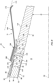
- the downstream fire seal 72 of FIG. 6 as well as the downstream inner support member 178 and the downstream outer support member 180 are mechanically attached to the nozzle ring 80 and its ring base 124 by a plurality of downstream seal-nozzle ring fasteners 182; e.g., bolts. These downstream seal-nozzle ring fasteners 182 are arranged and may (or may not) be equispaced circumferentially about the axis 30 and along the downstream fire seal 72.
- Each of the downstream seal-nozzle ring fasteners 182 includes a downstream fastener head 184 and a downstream fastener shank 186. The downstream fastener head 184 is radially abutted against or otherwise engaged with the downstream outer support member 180.
- the downstream fastener shank 186 projects longitudinally (e.g., generally radially inward) out from the downstream fastener head 184, sequentially through apertures (e.g., through-holes) in the respective members 180, 72, 178 and 82, and is threaded into a respective threaded blind aperture 188 in the nozzle ring 80 and its ring base 124.
- This blind aperture 188 projects partially longitudinally (e.g., generally radially inward) into the ring base 124 towards the axis 30 to a distal bottom end of the blind aperture 188.
- the blind aperture 188 may be formed by a threaded insert 190 (e.g., a helical coil, etc.) nested within a (e.g., unthreaded) blind hole 192 projecting longitudinally into the ring base 124 towards the axis 30.
- a threaded insert 190 e.g., a helical coil, etc.
- a blind hole 192 projecting longitudinally into the ring base 124 towards the axis 30.
- the respective members 180, 72, 178 and 82 are radially sandwiched and clamped between each downstream fastener head 184 and the nozzle ring 80 and its ring base 124.
- the downstream fire seal 72 may be disassembled and removed / replaced without also removing the nozzle fairing skin 82.
- the upstream fire seal 70 extends circumferentially about the axis 30 between circumferentially opposing ends 194 of the upstream fire seal 70.
- the upstream fire seal 70 extends axially along the axis 30 from an axial forward, upstream end 196 of the upstream fire seal 70 to an axial aft, downstream end 198 of the upstream fire seal 70.
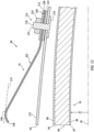
- the upstream fire seal 70 of FIG. 10 includes an upstream seal base 200 and an upstream seal spring 202 (e.g., a cantilevered spring seal element).
- the upstream seal spring 202 projects axially out from the upstream seal base 200 in the axial upstream direction to an axial unsupported distal end of the upstream seal spring 202; here, the upstream seal upstream end 196.
- the upstream seal spring 202 is angularly offset from the upstream seal base 200, at least at an interface between the upstream fire seal members 200 and 202, by an offset angle 204.
- This upstream seal offset angle 204 may be a non-zero acute offset angle between, for example, ten degrees (10°) and seventy degrees (70°) inclusive; e.g., between twenty-five degrees (25°) and thirty-five degrees (35°) inclusive.
- the upstream seal spring 202 may turn radially inward to provide the upstream fire seal 70 with a land 206 for interfacing with the pylon structure 174 for the aircraft propulsion system 20; e.g., see FIG. 11 .
- the upstream fire seal 70 of FIG. 10 may be formed by a stack of axially and circumferentially overlapping (e.g., parallel) leaf spring seals 208. Each of these leaf spring seals 208 may be constructed from a formed relatively thin sheet of resilient material; e.g., metal. The present disclosure, however, is not limited to such an exemplary upstream fire seal configuration.
- the upstream fire seal 70 is disposed radially outboard of the nozzle fairing skin 82 at, for example, an axial intermediate location between the fairing skin upstream end 146 and the downstream fire seal 72 (see FIG. 2 ).
- an arcuate upstream inner support member 210 e.g., a radial spacer and/or a radial gasket element
- An arcuate upstream outer support member 212 e.g., a radial clamping member
- the upstream seal base 200 is clamped radially between the upstream inner support member 210 and the upstream outer support member 212.
- the upstream fire seal 70 of FIG. 11 as well as the upstream inner support member 210 and the upstream outer support member 212 are mechanically attached to the nozzle fairing skin 82 by a plurality of upstream seal-fairing skin fastener assemblies 214.
- These upstream seal-fairing skin fastener assemblies 214 are arranged and may (or may not) be equispaced circumferentially about the axis 30 and along the downstream fire seal 72.
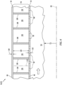
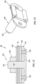
- Each of the upstream seal-fairing skin fastener assemblies 214 includes a stud plate 216, a threaded stud 218 and a nut 220.
- the stud plate 216 is disposed radially inboard of the nozzle fairing skin 82, and is radially spaced out from the nozzle wall 78.
- the stud plate 216 is radially abutted against or otherwise engages the nozzle fairing skin 82, and the stud plate 216 may be mounted to the nozzle fairing skin 82.
- the threaded stud 218 projects longitudinally (e.g., generally radially outwards) out from the respective stud plate 216, sequentially through apertures (e.g., through-holes) in the respective members 82, 210, 70 and 212, and to a distal stud end 222 of the threaded stud 218.
- the nut 220 is threaded onto the respective threaded stud 218 at its distal stud end 222.
- the nut 220 is disposed radially outboard of and is radially abutted against or otherwise engages the nozzle fairing skin 82.
- the respective members 82, 210, 70 and 212 are radially sandwiched and clamped between each stud plate 216 and the respective nut 220.
- an axial height of the respective upstream seal-fairing skin fastener assembly 214 inward of the nozzle fairing skin 82 may be minimized.
- each stud plate 216 may be mounted to the nozzle fairing skin 82 by one or more fasteners 224.
- fasteners 224 include, but are not limited to, rivets.
- each threaded stud 218 may be formed integral with or otherwise bonded to the respective stud plate 216. In other embodiments, referring to FIG. 13 , a head of each threaded stud 218 may be clamped to the respective stud plate 216.
- each stud plate 216 may be associated with a single respective one of the threaded studs 218. In other embodiments, referring to FIG. 14 , each stud plate 216 may be associated with multiple of the threaded studs 218.
- the exhaust nozzle 50 may be included in various gas turbine engines other than the one described above.
- the exhaust nozzle 50 for example, may be included in a geared gas turbine engine where a gear train connects one or more shafts to one or more rotors in a fan section, a compressor section and/or any other engine section.
- the exhaust nozzle 50 may be included in a direct drive gas turbine engine configured without a gear train.
- the exhaust nozzle 50 may be included in a gas turbine engine configured with a single spool, with two spools (e.g., see FIG. 1 ), or with more than two spools.
- the gas turbine engine may be configured as a turbofan engine, a turbojet engine, a propfan engine, a pusher fan engine or any other type of gas turbine engine with an exhaust nozzle.
- the present disclosure therefore is not limited to any particular types or configurations of gas turbine engines.
Landscapes
- Engineering & Computer Science (AREA)
- Chemical & Material Sciences (AREA)
- Combustion & Propulsion (AREA)
- Mechanical Engineering (AREA)
- General Engineering & Computer Science (AREA)
- Aviation & Aerospace Engineering (AREA)
- Turbine Rotor Nozzle Sealing (AREA)
- Gasket Seals (AREA)
- Jet Pumps And Other Pumps (AREA)
Applications Claiming Priority (1)
| Application Number | Priority Date | Filing Date | Title |
|---|---|---|---|
| US202363537682P | 2023-09-11 | 2023-09-11 |
Publications (2)
| Publication Number | Publication Date |
|---|---|
| EP4520946A2 true EP4520946A2 (fr) | 2025-03-12 |
| EP4520946A3 EP4520946A3 (fr) | 2025-06-25 |
Family
ID=92762101
Family Applications (3)
| Application Number | Title | Priority Date | Filing Date |
|---|---|---|---|
| EP24199799.8A Pending EP4520946A3 (fr) | 2023-09-11 | 2024-09-11 | Ensemble tuyère d'échappement pour système de propulsion d'aéronef |
| EP24199738.6A Pending EP4520945A3 (fr) | 2023-09-11 | 2024-09-11 | Ensemble tuyère d'échappement pour système de propulsion d'aéronef |
| EP24199863.2A Pending EP4520947A3 (fr) | 2023-09-11 | 2024-09-11 | Ensemble tuyère d'échappement pour système de propulsion d'aéronef |
Family Applications After (2)
| Application Number | Title | Priority Date | Filing Date |
|---|---|---|---|
| EP24199738.6A Pending EP4520945A3 (fr) | 2023-09-11 | 2024-09-11 | Ensemble tuyère d'échappement pour système de propulsion d'aéronef |
| EP24199863.2A Pending EP4520947A3 (fr) | 2023-09-11 | 2024-09-11 | Ensemble tuyère d'échappement pour système de propulsion d'aéronef |
Country Status (2)
| Country | Link |
|---|---|
| US (2) | US20250083828A1 (fr) |
| EP (3) | EP4520946A3 (fr) |
Family Cites Families (28)
| Publication number | Priority date | Publication date | Assignee | Title |
|---|---|---|---|---|
| US4013210A (en) * | 1972-08-21 | 1977-03-22 | Czeslaw Deminet | Method of diffusion bonding |
| GB8905894D0 (en) * | 1989-03-15 | 1989-04-26 | Rolls Royce Plc | Fluid-tight joints |
| US5143292A (en) | 1991-05-09 | 1992-09-01 | General Electric Company | Cooled leaf seal |
| US5524846A (en) * | 1993-12-21 | 1996-06-11 | The Boeing Company | Fire protection system for airplanes |
| US5560198A (en) | 1995-05-25 | 1996-10-01 | United Technologies Corporation | Cooled gas turbine engine augmentor fingerseal assembly |
| US5592813A (en) * | 1995-07-06 | 1997-01-14 | Avaero | Hush kit for jet engine |
| US5906097A (en) * | 1997-03-28 | 1999-05-25 | The Boeing Company | Engine flow control device |
| US6532729B2 (en) | 2001-05-31 | 2003-03-18 | General Electric Company | Shelf truncated chevron exhaust nozzle for reduction of exhaust noise and infrared (IR) signature |
| US7305817B2 (en) | 2004-02-09 | 2007-12-11 | General Electric Company | Sinuous chevron exhaust nozzle |
| RU2310766C1 (ru) | 2006-02-06 | 2007-11-20 | Открытое акционерное общество "Авиадвигатель" | Шевронное реактивное сопло газотурбинного двигателя |
| DE102006019299B3 (de) | 2006-04-26 | 2007-11-08 | Deutsches Zentrum für Luft- und Raumfahrt e.V. | Ummanteltes Turbofan-Flugzeugtriebwerk |
| US7926285B2 (en) * | 2007-07-18 | 2011-04-19 | General Electric Company | Modular chevron exhaust nozzle |
| US20090165926A1 (en) * | 2007-10-24 | 2009-07-02 | United Technologies Corporation | Method and assembly for bonding metal layers in a gas turbine engine using a polyimide adhesive |
| US8671693B2 (en) * | 2008-01-11 | 2014-03-18 | George C. P. Straza | Thermally conductive structure |
| BRPI0822611B1 (pt) * | 2008-04-22 | 2020-07-21 | Tecnomagnete S.P.A. | aparelho magnético monolítico e processo para fabricar o dito aparelho magnético monolítico |
| US20100193605A1 (en) | 2009-01-30 | 2010-08-05 | Michael Robert Johnson | Thermally balanced aero structures |
| US8356468B2 (en) | 2009-06-12 | 2013-01-22 | The Boeing Company | Gas turbine engine nozzle configurations |
| US9643733B2 (en) * | 2014-06-17 | 2017-05-09 | The Boeing Company | Fire seal for an aircraft |
| WO2016000673A1 (fr) | 2014-06-30 | 2016-01-07 | Rudolf Ganz | Tuyère à chevrons |
| EP3165778B1 (fr) * | 2015-11-05 | 2020-01-01 | MTU Aero Engines GmbH | Systeme de liaison d'elements de turbomachine |
| FR3047768B1 (fr) | 2016-02-17 | 2019-02-01 | Safran Power Units | Dispositif de liaison et d'etancheite entre deux modules d'un conduit d'echappement d'une turbomachine |
| US10364748B2 (en) | 2016-08-19 | 2019-07-30 | United Technologies Corporation | Finger seal flow metering |
| DE102016217033A1 (de) * | 2016-09-07 | 2018-03-08 | Rolls-Royce Deutschland Ltd & Co Kg | Mischerbaugruppe für ein Turbofan-Triebwerk |
| FR3074148B1 (fr) * | 2017-11-30 | 2020-11-06 | Safran Nacelles | Panneau acoustique pour nacelle de turboreacteur d’aeronef et procede de fabrication d’un element d’une nacelle |
| FR3100845B1 (fr) | 2019-09-13 | 2022-07-08 | Safran Nacelles | Organe de tuyère extérieur pour turbomachine |
| US11535390B2 (en) * | 2020-02-28 | 2022-12-27 | Rohr, Inc. | Structural panel with integrated coupler |
| US12292014B2 (en) * | 2020-12-21 | 2025-05-06 | Rohr, Inc. | Gas turbine engine exhaust chevrons |
| US20230175458A1 (en) * | 2021-12-06 | 2023-06-08 | Rohr, Inc. | Multi-core acoustic panel for an aircraft propulsion system |
-
2024
- 2024-09-11 EP EP24199799.8A patent/EP4520946A3/fr active Pending
- 2024-09-11 US US18/882,286 patent/US20250083828A1/en active Pending
- 2024-09-11 US US18/882,328 patent/US12576982B2/en active Active
- 2024-09-11 EP EP24199738.6A patent/EP4520945A3/fr active Pending
- 2024-09-11 EP EP24199863.2A patent/EP4520947A3/fr active Pending
Also Published As
| Publication number | Publication date |
|---|---|
| EP4520947A3 (fr) | 2025-06-25 |
| US20250083828A1 (en) | 2025-03-13 |
| EP4520945A3 (fr) | 2025-07-09 |
| US12576982B2 (en) | 2026-03-17 |
| EP4520946A3 (fr) | 2025-06-25 |
| EP4520945A2 (fr) | 2025-03-12 |
| US20250083829A1 (en) | 2025-03-13 |
| EP4520947A2 (fr) | 2025-03-12 |
Similar Documents
| Publication | Publication Date | Title |
|---|---|---|
| US9200537B2 (en) | Gas turbine exhaust case with acoustic panels | |
| US12000300B2 (en) | Exhaust cone for a turbomachine | |
| EP4206448B1 (fr) | Panneau acoustique multicoeur pour système de propulsion d'aéronef | |
| EP4191040A1 (fr) | Panneau acoustique multicoeur pour système de propulsion d'aéronef | |
| US20250214712A1 (en) | Acoustic panel for an aircraft propulsion system | |
| US20250214713A1 (en) | Acoustic panel for an aircraft propulsion system | |
| EP3273013A1 (fr) | Ensemble pour un moteur à turbine | |
| US12576982B2 (en) | Exhaust nozzle assembly for aircraft propulsion system | |
| EP4015812A1 (fr) | Chevrons d'échappement de moteur à turbine à gaz | |
| US11371351B2 (en) | Multi-disk bladed rotor assembly for rotational equipment | |
| US11401814B2 (en) | Rotor assembly with internal vanes | |
| US11339673B2 (en) | Rotor assembly with internal vanes | |
| US12559249B2 (en) | Engine exhaust center body with acoustic attenuation | |
| EP4332364A1 (fr) | Tuyère d'échappement de moteur à atténuation acoustique | |
| EP4534509A2 (fr) | Ensemble rotor à aubes à disques multiples pour équipement rotatif | |
| EP4524366A2 (fr) | Buse d'injecteur multi-pièce pour turbomachine | |
| EP4575213A1 (fr) | Corps central d'échappement de moteur acoustique à peau interne effilée | |
| US12515807B2 (en) | Bolted connection between mounting bracket and aircraft engine case(s) | |
| EP4678901A2 (fr) | Moteur à turbine à gaz avec système d'actionnement intégré | |
| EP4600947A1 (fr) | Panneau acoustique ayant différentes configurations de cellules | |
| EP4148291A2 (fr) | Arbre de moteur à turbine à gaz avec structure de support à lobes | |
| EP4621193A1 (fr) | Centrale électrique d'aéronef avec protection d'articulation | |
| EP4692511A1 (fr) | Agencements pour un moteur à turbine | |
| EP4528078A2 (fr) | Paroi de trajet d'écoulement à matériaux multiples pour moteur à turbine | |
| US20210222567A1 (en) | Rotor blade and method for forming a rotor blade |
Legal Events
| Date | Code | Title | Description |
|---|---|---|---|
| PUAI | Public reference made under article 153(3) epc to a published international application that has entered the european phase |
Free format text: ORIGINAL CODE: 0009012 |
|
| STAA | Information on the status of an ep patent application or granted ep patent |
Free format text: STATUS: THE APPLICATION HAS BEEN PUBLISHED |
|
| AK | Designated contracting states |
Kind code of ref document: A2 Designated state(s): AL AT BE BG CH CY CZ DE DK EE ES FI FR GB GR HR HU IE IS IT LI LT LU LV MC ME MK MT NL NO PL PT RO RS SE SI SK SM TR |
|
| PUAL | Search report despatched |
Free format text: ORIGINAL CODE: 0009013 |
|
| AK | Designated contracting states |
Kind code of ref document: A3 Designated state(s): AL AT BE BG CH CY CZ DE DK EE ES FI FR GB GR HR HU IE IS IT LI LT LU LV MC ME MK MT NL NO PL PT RO RS SE SI SK SM TR |
|
| RIC1 | Information provided on ipc code assigned before grant |
Ipc: F02K 1/38 20060101AFI20250521BHEP |
|
| STAA | Information on the status of an ep patent application or granted ep patent |
Free format text: STATUS: REQUEST FOR EXAMINATION WAS MADE |
|
| 17P | Request for examination filed |
Effective date: 20251224 |