EP4534509A2 - Ensemble rotor à aubes à disques multiples pour équipement rotatif - Google Patents
Ensemble rotor à aubes à disques multiples pour équipement rotatif Download PDFInfo
- Publication number
- EP4534509A2 EP4534509A2 EP25159515.3A EP25159515A EP4534509A2 EP 4534509 A2 EP4534509 A2 EP 4534509A2 EP 25159515 A EP25159515 A EP 25159515A EP 4534509 A2 EP4534509 A2 EP 4534509A2
- Authority
- EP
- European Patent Office
- Prior art keywords
- rotor
- disk
- attachment
- rotor disk
- Prior art date
- Legal status (The legal status is an assumption and is not a legal conclusion. Google has not performed a legal analysis and makes no representation as to the accuracy of the status listed.)
- Pending
Links
Images













Classifications
-
- F—MECHANICAL ENGINEERING; LIGHTING; HEATING; WEAPONS; BLASTING
- F01—MACHINES OR ENGINES IN GENERAL; ENGINE PLANTS IN GENERAL; STEAM ENGINES
- F01D—NON-POSITIVE DISPLACEMENT MACHINES OR ENGINES, e.g. STEAM TURBINES
- F01D5/00—Blades; Blade-carrying members; Heating, heat-insulating, cooling or antivibration means on the blades or the members
- F01D5/02—Blade-carrying members, e.g. rotors
- F01D5/06—Rotors for more than one axial stage, e.g. of drum or multiple disc type; Details thereof, e.g. shafts, shaft connections
-
- F—MECHANICAL ENGINEERING; LIGHTING; HEATING; WEAPONS; BLASTING
- F01—MACHINES OR ENGINES IN GENERAL; ENGINE PLANTS IN GENERAL; STEAM ENGINES
- F01D—NON-POSITIVE DISPLACEMENT MACHINES OR ENGINES, e.g. STEAM TURBINES
- F01D5/00—Blades; Blade-carrying members; Heating, heat-insulating, cooling or antivibration means on the blades or the members
- F01D5/30—Fixing blades to rotors; Blade roots ; Blade spacers
- F01D5/3069—Fixing blades to rotors; Blade roots ; Blade spacers between two discs or rings
-
- F—MECHANICAL ENGINEERING; LIGHTING; HEATING; WEAPONS; BLASTING
- F01—MACHINES OR ENGINES IN GENERAL; ENGINE PLANTS IN GENERAL; STEAM ENGINES
- F01D—NON-POSITIVE DISPLACEMENT MACHINES OR ENGINES, e.g. STEAM TURBINES
- F01D21/00—Shutting-down of machines or engines, e.g. in emergency; Regulating, controlling, or safety means not otherwise provided for
- F01D21/04—Shutting-down of machines or engines, e.g. in emergency; Regulating, controlling, or safety means not otherwise provided for responsive to undesired position of rotor relative to stator or to breaking-off of a part of the rotor, e.g. indicating such position
- F01D21/045—Shutting-down of machines or engines, e.g. in emergency; Regulating, controlling, or safety means not otherwise provided for responsive to undesired position of rotor relative to stator or to breaking-off of a part of the rotor, e.g. indicating such position special arrangements in stators or in rotors dealing with breaking-off of part of rotor
-
- F—MECHANICAL ENGINEERING; LIGHTING; HEATING; WEAPONS; BLASTING
- F01—MACHINES OR ENGINES IN GENERAL; ENGINE PLANTS IN GENERAL; STEAM ENGINES
- F01D—NON-POSITIVE DISPLACEMENT MACHINES OR ENGINES, e.g. STEAM TURBINES
- F01D5/00—Blades; Blade-carrying members; Heating, heat-insulating, cooling or antivibration means on the blades or the members
- F01D5/02—Blade-carrying members, e.g. rotors
- F01D5/08—Heating, heat-insulating or cooling means
- F01D5/085—Heating, heat-insulating or cooling means cooling fluid circulating inside the rotor
- F01D5/087—Heating, heat-insulating or cooling means cooling fluid circulating inside the rotor in the radial passages of the rotor disc
-
- F—MECHANICAL ENGINEERING; LIGHTING; HEATING; WEAPONS; BLASTING
- F01—MACHINES OR ENGINES IN GENERAL; ENGINE PLANTS IN GENERAL; STEAM ENGINES
- F01D—NON-POSITIVE DISPLACEMENT MACHINES OR ENGINES, e.g. STEAM TURBINES
- F01D5/00—Blades; Blade-carrying members; Heating, heat-insulating, cooling or antivibration means on the blades or the members
- F01D5/12—Blades
- F01D5/28—Selecting particular materials; Particular measures relating thereto; Measures against erosion or corrosion
- F01D5/282—Selecting composite materials, e.g. blades with reinforcing filaments
-
- F—MECHANICAL ENGINEERING; LIGHTING; HEATING; WEAPONS; BLASTING
- F01—MACHINES OR ENGINES IN GENERAL; ENGINE PLANTS IN GENERAL; STEAM ENGINES
- F01D—NON-POSITIVE DISPLACEMENT MACHINES OR ENGINES, e.g. STEAM TURBINES
- F01D5/00—Blades; Blade-carrying members; Heating, heat-insulating, cooling or antivibration means on the blades or the members
- F01D5/12—Blades
- F01D5/28—Selecting particular materials; Particular measures relating thereto; Measures against erosion or corrosion
- F01D5/284—Selection of ceramic materials
-
- F—MECHANICAL ENGINEERING; LIGHTING; HEATING; WEAPONS; BLASTING
- F01—MACHINES OR ENGINES IN GENERAL; ENGINE PLANTS IN GENERAL; STEAM ENGINES
- F01D—NON-POSITIVE DISPLACEMENT MACHINES OR ENGINES, e.g. STEAM TURBINES
- F01D5/00—Blades; Blade-carrying members; Heating, heat-insulating, cooling or antivibration means on the blades or the members
- F01D5/30—Fixing blades to rotors; Blade roots ; Blade spacers
- F01D5/3084—Fixing blades to rotors; Blade roots ; Blade spacers the blades being made of ceramics
-
- F—MECHANICAL ENGINEERING; LIGHTING; HEATING; WEAPONS; BLASTING
- F05—INDEXING SCHEMES RELATING TO ENGINES OR PUMPS IN VARIOUS SUBCLASSES OF CLASSES F01-F04
- F05D—INDEXING SCHEME FOR ASPECTS RELATING TO NON-POSITIVE-DISPLACEMENT MACHINES OR ENGINES, GAS-TURBINES OR JET-PROPULSION PLANTS
- F05D2220/00—Application
- F05D2220/30—Application in turbines
- F05D2220/32—Application in turbines in gas turbines
-
- F—MECHANICAL ENGINEERING; LIGHTING; HEATING; WEAPONS; BLASTING
- F05—INDEXING SCHEMES RELATING TO ENGINES OR PUMPS IN VARIOUS SUBCLASSES OF CLASSES F01-F04
- F05D—INDEXING SCHEME FOR ASPECTS RELATING TO NON-POSITIVE-DISPLACEMENT MACHINES OR ENGINES, GAS-TURBINES OR JET-PROPULSION PLANTS
- F05D2240/00—Components
- F05D2240/10—Stators
- F05D2240/12—Fluid guiding means, e.g. vanes
- F05D2240/126—Baffles or ribs
-
- F—MECHANICAL ENGINEERING; LIGHTING; HEATING; WEAPONS; BLASTING
- F05—INDEXING SCHEMES RELATING TO ENGINES OR PUMPS IN VARIOUS SUBCLASSES OF CLASSES F01-F04
- F05D—INDEXING SCHEME FOR ASPECTS RELATING TO NON-POSITIVE-DISPLACEMENT MACHINES OR ENGINES, GAS-TURBINES OR JET-PROPULSION PLANTS
- F05D2240/00—Components
- F05D2240/20—Rotors
- F05D2240/24—Rotors for turbines
-
- F—MECHANICAL ENGINEERING; LIGHTING; HEATING; WEAPONS; BLASTING
- F05—INDEXING SCHEMES RELATING TO ENGINES OR PUMPS IN VARIOUS SUBCLASSES OF CLASSES F01-F04
- F05D—INDEXING SCHEME FOR ASPECTS RELATING TO NON-POSITIVE-DISPLACEMENT MACHINES OR ENGINES, GAS-TURBINES OR JET-PROPULSION PLANTS
- F05D2250/00—Geometry
- F05D2250/10—Two-dimensional
- F05D2250/14—Two-dimensional elliptical
-
- F—MECHANICAL ENGINEERING; LIGHTING; HEATING; WEAPONS; BLASTING
- F05—INDEXING SCHEMES RELATING TO ENGINES OR PUMPS IN VARIOUS SUBCLASSES OF CLASSES F01-F04
- F05D—INDEXING SCHEME FOR ASPECTS RELATING TO NON-POSITIVE-DISPLACEMENT MACHINES OR ENGINES, GAS-TURBINES OR JET-PROPULSION PLANTS
- F05D2250/00—Geometry
- F05D2250/10—Two-dimensional
- F05D2250/18—Two-dimensional patterned
- F05D2250/183—Two-dimensional patterned zigzag
-
- F—MECHANICAL ENGINEERING; LIGHTING; HEATING; WEAPONS; BLASTING
- F05—INDEXING SCHEMES RELATING TO ENGINES OR PUMPS IN VARIOUS SUBCLASSES OF CLASSES F01-F04
- F05D—INDEXING SCHEME FOR ASPECTS RELATING TO NON-POSITIVE-DISPLACEMENT MACHINES OR ENGINES, GAS-TURBINES OR JET-PROPULSION PLANTS
- F05D2250/00—Geometry
- F05D2250/20—Three-dimensional
- F05D2250/23—Three-dimensional prismatic
-
- F—MECHANICAL ENGINEERING; LIGHTING; HEATING; WEAPONS; BLASTING
- F05—INDEXING SCHEMES RELATING TO ENGINES OR PUMPS IN VARIOUS SUBCLASSES OF CLASSES F01-F04
- F05D—INDEXING SCHEME FOR ASPECTS RELATING TO NON-POSITIVE-DISPLACEMENT MACHINES OR ENGINES, GAS-TURBINES OR JET-PROPULSION PLANTS
- F05D2260/00—Function
- F05D2260/30—Retaining components in desired mutual position
- F05D2260/31—Retaining bolts or nuts
-
- F—MECHANICAL ENGINEERING; LIGHTING; HEATING; WEAPONS; BLASTING
- F05—INDEXING SCHEMES RELATING TO ENGINES OR PUMPS IN VARIOUS SUBCLASSES OF CLASSES F01-F04
- F05D—INDEXING SCHEME FOR ASPECTS RELATING TO NON-POSITIVE-DISPLACEMENT MACHINES OR ENGINES, GAS-TURBINES OR JET-PROPULSION PLANTS
- F05D2260/00—Function
- F05D2260/30—Retaining components in desired mutual position
- F05D2260/36—Retaining components in desired mutual position by a form fit connection, e.g. by interlocking
-
- F—MECHANICAL ENGINEERING; LIGHTING; HEATING; WEAPONS; BLASTING
- F05—INDEXING SCHEMES RELATING TO ENGINES OR PUMPS IN VARIOUS SUBCLASSES OF CLASSES F01-F04
- F05D—INDEXING SCHEME FOR ASPECTS RELATING TO NON-POSITIVE-DISPLACEMENT MACHINES OR ENGINES, GAS-TURBINES OR JET-PROPULSION PLANTS
- F05D2300/00—Materials; Properties thereof
- F05D2300/60—Properties or characteristics given to material by treatment or manufacturing
- F05D2300/603—Composites; e.g. fibre-reinforced
- F05D2300/6033—Ceramic matrix composites [CMC]
-
- Y—GENERAL TAGGING OF NEW TECHNOLOGICAL DEVELOPMENTS; GENERAL TAGGING OF CROSS-SECTIONAL TECHNOLOGIES SPANNING OVER SEVERAL SECTIONS OF THE IPC; TECHNICAL SUBJECTS COVERED BY FORMER USPC CROSS-REFERENCE ART COLLECTIONS [XRACs] AND DIGESTS
- Y02—TECHNOLOGIES OR APPLICATIONS FOR MITIGATION OR ADAPTATION AGAINST CLIMATE CHANGE
- Y02T—CLIMATE CHANGE MITIGATION TECHNOLOGIES RELATED TO TRANSPORTATION
- Y02T50/00—Aeronautics or air transport
- Y02T50/60—Efficient propulsion technologies, e.g. for aircraft
Definitions
- This disclosure relates generally to rotational equipment and, more particularly, to rotor blades and associated rotor assemblies.
- Gas turbine engine designers are continually being challenged to provide gas turbine engines with improved performance at reduced weights.
- One design metric being pushed to provide improved performance is increasing turbine rotational speed.
- rotor disk bores also increase in size in order to accommodate increasing centrifugal loading. This can result in bore widths that are so large that heat treating the center of a bore may become challenging.
- Rotor disk sizing may also be impacted by rim pull which includes the mass of airfoils and interrupted (circumferentially discontinuous) features created by axially or angled airfoil attachment features.
- the airfoil projects radially out from the platform.
- the neck extends radially between and connects the platform and the attachment.
- a first end portion of the attachment projects axially along the rotational axis away from the neck and into a first pocket in the first rotor disk.
- a second end portion of the attachment projects axially along the rotational axis away from the neck and into a second pocket in the second rotor disk.
- the rotor blades may also include a second rotor blade.
- the second rotor blade may include a second attachment projecting axially along the rotational axis into a third pocket in the first rotor disk and a fourth pocket in the second rotor disk.
- a second portion of the first rotor disk may extend circumferentially across and thereby circumferentially cover the second attachment.
- the second rotor blade may circumferentially neighbor the first rotor blade.
- a portion of the second rotor disk may extend circumferentially across and thereby circumferentially cover the attachment.
- the first rotor blade may be configured from or otherwise include ceramic.
- the first rotor blade may be configured from or otherwise include metal.
- the first rotor blade may be configured from or otherwise include intermetallic material.
- the rotor assembly may also include a plurality of disk mounts connecting the first rotor disk and the second rotor disk together.
- the rotor assembly may also include a reinforcing ring located axially between and rotatable with the first rotor disk and the second rotor disk.
- the rotor assembly may also include a first reinforcing ring and/or a second reinforcing ring.
- the first reinforcing ring may be connected to an exterior of the first rotor disk.
- the second reinforcing ring may be connected to an exterior of the second rotor disk.
- the present disclosure may include any one or more of the individual features disclosed above and/or below alone or in any combination thereof.
- FIG. 1 illustrates a bladed rotor assembly 100 for rotational equipment with an axial centerline 102, which centerline 102 may be or may be coaxial with an axis of rotation (e.g., a rotational axis) of the rotor assembly 100.
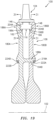
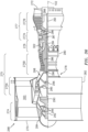
- An example of such rotational equipment is a gas turbine engine for an aircraft propulsion system, an exemplary embodiment of which is described below in further detail with respect to FIG. 36 .
- the rotor assembly 100 of the present disclosure is not limited to such an aircraft application nor a gas turbine engine application.
- the rotor assembly 100 may alternatively be configured with rotational equipment such as an industrial gas turbine engine, a wind turbine, a water turbine or any other apparatus which includes a bladed rotor.
- the rotor assembly 100 of FIG. 1 includes a plurality of rotor blades 104 and a rotor disk assembly 106.
- each of the rotor blades 104 may be configured as a rotor blade singlet; e.g., a rotor blade that only includes a single airfoil.
- the present disclosure is not limited to such an exemplary rotor blade configuration.
- one or more or each of the rotor blades 104 may alternatively be configured as a rotor blade doublet with a pair of airfoils.
- each rotor blade 104 includes a rotor blade mount 108 and a rotor blade airfoil 110.
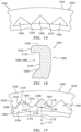
- the rotor blade mount 108 of FIGS. 2 and 3 includes a mount platform 112, a mount neck 114 and a mount attachment 116.
- the mount platform 112 is configured to form a portion of an inner peripheral boarder of a gas path 118 (e.g., a core gas path) that extends axially along the axial centerline 102 across the rotor assembly 100; e.g., a gas path into which the airfoils 110 radially extend.
- the mount platform 112 for example, extends radially relative to the axial centerline 102 between a platform inner end 120 and a platform outer end 122.
- the platform outer end 122 carriers a gas path surface 124, which forms the respective inner peripheral boarder portion of the gas path 118. As best seen in FIG.
- the gas path surface 124 extends axially between a platform first (e.g., forward and/or upstream) side 126 and a platform second (e.g., aft and/or downstream) side 128. As best seen in FIG. 2 , the gas path surface 124 extends laterally (e.g., circumferentially or tangentially) between opposing platform lateral sides 130 and 132.
- the mount platform 112 is configured with one or more lateral platform overhangs 134 and 136; e.g., wings, flanges, projections, etc.
- One or both of these platform overhangs 134 and 136 may have a tapered geometry.
- a radial thickness of the mount platform 112 of FIG. 2 decreases (e.g., tapers) as the mount platform 112 and its first platform overhang 134 extend laterally from a laterally intermediate location towards or to the first lateral side 130. This change in thickness provides the first platform overhang 134 with its tapered geometry.
- the radial thickness of the mount platform 112 of FIG. 2 also decreases as the mount platform 112 and its second platform overhang 136 extend laterally from the laterally intermediate location towards or to the second lateral side 132. This change in thickness provides the second platform overhang 136 with its tapered geometry.
- the mount neck 114 is located radially beneath the mount platform 112.
- the mount neck 114 extends radially between and is connected (e.g., directly) to the mount platform 112 and the mount attachment 116.
- the mount neck 114 extends laterally between opposing neck lateral sides 138 and 140.
- the neck first lateral side 138 is laterally recessed inward from the platform first lateral side 130 such that the first platform overhang 134 projects laterally out from the mount neck 114.
- the neck second lateral side 140 is laterally recessed inward from the platform second lateral side 132 such that the second platform overhang 136 projects laterally out from the mount neck 114.
- the mount neck 114 extends axially along the axial centerline 102 between a neck first (e.g., forward and/or upstream) side 142 and a neck second (e.g., aft and/or downstream) side 144.
- the neck first side 142 is axially recessed inward from the platform first side 126 such that the mount platform 112 and its elements 134 and 136 project axially out from the mount neck 114.
- the neck second side 144 is axially recessed inward from the platform second side 128 such that the mount platform 112 and its elements 134 and 136 project axially out from the mount neck 114.
- the mount attachment 116 is located radially beneath the mount neck 114.
- the mount attachment 116 of FIGS. 2 and 3 is configured as a dovetail attachment; e.g., a flared attachment, a delta attachment, etc.
- the mount attachment 116 extends axially along the axial centerline 102 between an attachment first (e.g., forward and/or upstream) axial side 146 and an attachment second (e.g., aft and/or downstream) axial side 148.
- the mount attachment 116 extends laterally between opposing attachment lateral sides 150 and 152.
- the mount attachment 116 includes one or more attachment pressure surfaces 154 and 156 (e.g., engagement surfaces) and a bottom surface 158.
- the first attachment pressure surface 154 is arranged to the first lateral side 150 of the mount attachment 116 and the second attachment pressure surface 156 is arranged to the second lateral side 152 of the mount attachment 116.
- the first and the second attachment pressure surfaces 154 and 156 may meet (e.g., be joined) at an outer peak of the mount attachment 116.
- the first and the second attachment pressure surfaces 154 and 156 may also respectively meet the neck lateral sides 138 and 140 at interfaces between the mount attachment 116 and the mount neck 114; see also FIG. 3 .
- Each of the attachment pressure surfaces 154, 156 of FIGS. 2 and 3 is a substantially planar surface.
- the first attachment pressure surface 154 and/or the second attachment pressure surface 156 may have a non-planar (e.g., curved and/or compound angled) geometry.
- the attachment pressure surfaces 154, 156 are angularly offset from one another by an included angle 160. This angle 160 may be greater than sixty degrees (60°) and less than one hundred and forty degrees (140°). The present disclosure, however, is not limited to such exemplary angles.
- the bottom surface 158 of FIG. 2 extends laterally between respective radial inner ends of the attachment pressure surfaces 154 and 156.
- the first attachment pressure surface 154 extends radially between the bottom surface 158 and the first neck lateral side 138.
- the second attachment pressure surface 156 extends radially between the bottom surface 158 and the second neck lateral side 140.
- an axial first end portion 162 (e.g., a cantilevered projection) of the mount attachment 116 projects axially out from the neck first side 142.
- the rotor blade mount 108 is thereby configured with a first gap 164 (e.g., a recess, a notch, etc.) axially adjacent the mount neck 114, which first gap 164 extends radially between the axial first end portion 162 of the mount attachment 116 and the mount platform 112.
- an axial second end portion 166 (e.g., a cantilevered projection) of the mount attachment 116 projects axially out from the neck second side 144.
- the rotor blade mount 108 is thereby configured with a second gap 168 (e.g., a recess, a notch, etc.) axially adjacent the mount neck 114, which second gap 168 extends radially between the axial second end portion 166 of the mount attachment 116 and the mount platform 112.
- a second gap 168 e.g., a recess, a notch, etc.
- the rotor disk assembly 106 includes a plurality of rotor disks such as a first (e.g., upstream / forward) rotor disk 180A and a second (e.g., downstream / aft) rotor disk 180B.
- Each rotor disk 180A, 180B (generally referred to as "180") extends circumferentially about (e.g., complete around) the axial centerline 102 to provide that rotor disk 180 with a full hoop, annular body.
- This annular body may be a monolithic body.
- the annular body may be formed from a plurality of interconnected arcuate circumferential segments; e.g., disk halves, disk thirds, disk quarters, etc.
- one or more or each of the first disk mount apertures 194A may have a non-circular geometry (e.g., an elliptical cross-sectional geometry, a polygonal (e.g., rectilinear) cross-sectional geometry, etc.) or any other geometry selected to accommodate a respective one of the disk mounts 188B as described below.
- a non-circular geometry e.g., an elliptical cross-sectional geometry, a polygonal (e.g., rectilinear) cross-sectional geometry, etc.
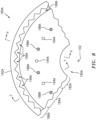
- the first rim 186A is configured with one or more first disk pockets 196A located at (e.g., on, adjacent or proximate) an outer end of the first rim 186A. These first disk pockets 196A are arranged circumferentially around the axial centerline 102 in an annular array.
- the first disk pockets 196A of FIG. 8 are circumferentially interconnected so as to form an (e.g., serrated) annular groove 198A in the first rim 186A.
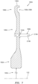
- the first disk pockets 196A may be discrete from one another and separated by divider portions 200A of the first rim 186A as shown, for example, in FIG. 9 .
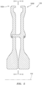
- each of the first disk pockets 196A projects axially along the axial centerline 102 partially into first rim 186A from an axial interior side 202A of the first rotor disk 180A to a first disk pocket end surface 204A.
- each of the first disk pockets 196A extends radially within the first rim 186A from a first disk pocket inner (e.g., bottom) surface 206A to a pair of first disk pressure surfaces 208A and 210A.
- Each of the first disk pockets 196A extends laterally within the first rim 186A between the pair of first disk pressure surfaces 208A and 210A as well as between circumferentially neighboring first disk pockets 196A.
- the first disk pocket end surface 204A extends radially between the first disk pocket inner surface 206A and the pair of first disk pressure surfaces 208A and 210A.
- the first disk pocket end surface 204A extends laterally between the pair of first disk pressure surfaces 208A and 210A.
- the first disk pocket end surface 204A also extends laterally between pressure surfaces 208A, 210A of circumferentially neighboring first disk pockets 196A.
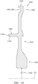
- the first disk pocket end surface 204A thereby may axially enclose an axial end of a respect first disk pocket 196A; see FIG. 10 .
- the first disk pressure surface 208A is arranged to a first lateral side of the first disk pocket 196A and the first disk pressure surface 210A is arranged to a second lateral side of the first disk pocket 196A.
- the first disk pressure surfaces 208A and 210A may meet (e.g., be joined) at an outer peak 212A of the first disk pocket 196A.
- the first disk pressure surfaces 208A and 210A may thereby radially enclose the respective first disk pocket 196A within the first rim 186A.
- Each of the first disk pressure surfaces 208A and 210A of FIG. 11 is a substantially planar surface.
- the first disk pressure surface 208A and/or the first disk pressure surface 208B may have a non-planar (e.g., curved and/or compound angled) geometry.
- the first disk pressure surfaces 208A and 210A are angularly offset from one another by an included angle 214A. This angle 214A may be greater than sixty degrees (60°) and less than one hundred and forty degrees (140°). The present disclosure, however, is not limited to such exemplary angles.
- the disk pressure surfaces 208A and 210A are configured to compliment the attachment pressure surfaces 154 and 156 to facilitate engagement between the mount attachments 116 and the first rotor disk 180A as described below in further detail; however, such a correspondence is not required. Furthermore, while an angle 215A between the first disk pressure surface 208A and a ray 217A from the centerline 102 and an angle 219A between the first disk pressure surface 210A and the ray 217A are shown as equal in FIG.
- the angle 215A may alternatively be different (e.g., greater or less) than the angle 219A (e.g., the first disk pocket 196A may be an asymmetric first disk pocket) in other embodiments.
- the first disk mounts 188A are arranged circumferentially around the axial centerline 102 in an annular array and are interposed with the first disk mount apertures 194A as described above.
- the first disk mounts 188A are radially aligned with the first disk mount apertures 194A; see also FIG. 7 .
- Each first disk mount 188A of FIG. 6 is connected to (e.g., formed integral with) the first web 184A.
- Each first disk mount 188A projects axially out from and is cantilevered from the first web 184A in a first axial direction (e.g., an aft / downstream direction) to a distal first disk mount end 216A.
- the second web 184B is configured with one or more second disk mount apertures 194B (e.g., through-holes). These second disk mount apertures 194B may be radially intermediately located between the second hub 182B and the second rim 186B. Note, the second disk mount 188B in FIG. 13 is shown out of plane for reference in order to illustrate the relative positioning of aperture second disk mount apertures 194B.
- each of the second disk pockets 196B projects axially along the axial centerline 102 partially into second rim 186B from an axial interior side 202B of the second rotor disk 180B to a second disk pocket end surface 204B.
- each of the second disk pockets 196B extends radially within the second rim 186B from a second disk pocket inner (e.g., bottom) surface 206B to a pair of second disk pressure surfaces 208B and 210B.
- Each of the second disk pockets 196B extends laterally within the second rim 186B between the pair of second disk pressure surfaces 208B and 210B as well as between circumferentially neighboring second disk pockets 196B.
- the angle 215B may alternatively be different (e.g., greater or less) than the angle 219B (e.g., the second disk pocket 196B may be an asymmetric second disk pocket) in other embodiments.
- the second disk mounts 188B are arranged circumferentially around the axial centerline 102 in an annular array and are interposed with the second disk mount apertures 194B as described above.
- the second disk mounts 188B are radially aligned with the second disk mount apertures 194B; see also FIG. 13 .
- Each second disk mount 188B of FIG. 12 is connected to (e.g., formed integral with) the second web 184B.
- Each rotor disks 180 and its various components may be configured as a monolithic body.
- the present disclosure is not limited to such an exemplary configuration.
- the disk mounts 188A, 188B (generally referred to as "188") may be discrete from (e.g., removable from) each of the rotor disks 180 as described below in further detail.
- These reinforcing ring(s) 400 are configured to assist the respective rotor disks 180 in carrying loads induced by rotation of the disk 180 and rotor assembly 100.
- These reinforcing ring(s) 400 may be integral with one or more disk elements (e.g., bonded into a pocket 402, 404 in or on the disk 180, bonded to a flange 406 on the disk 180) or mechanically attached with disk element(s).
- Each reinforcing ring 400 may be located within a respective rotor disk 180 (e.g., within the internal pocket 404; see FIG. 43 ), axially between the rotor disks 180 (e.g., in the pocket 402 and trapped between the webs 184; see FIG.
- the rotor blades 104 are mated with the first rotor disk 180A and the second rotor disk 180B.
- the rotor blades 104 for example, are arranged circumferentially around the axial centerline 102 in an annular array, and captured between and mounted to the first rim 186A and the second rim 186B.
- each mount attachment 116 is mated with a respective one of the first disk pockets 196A.
- the axial first end portion 162 of each mount attachment 116 projects axially (in the second axial direction) into the respective first disk pocket 196A.
- the attachment first axial side 146 is axially adjacent and may be abutted against (e.g., contact or otherwise engage) the first disk pocket end surface 204A.
- a portion of the first rotor disk 180A thereby extends laterally across and thereby laterally covers the respective mount attachment 116 and its axial first end portion 162.
- the attachment pressure surface 154 is arranged adjacent and configured to engage (e.g., contact) the first disk pressure surface 208A.
- the attachment pressure surface 156 is arranged adjacent and configured to engage the first disk pressure surface 210A.
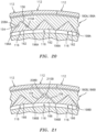
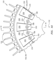
- a portion 220A of the first rotor disk 180A projects axially into the first gap 164.
- the first disk portion 220A is thereby disposed radially between the axial first end portion 162 of the respective mount attachment 116 and the respective mount platform 112; see also FIG. 20 .
- the first rotor disk 180A may substantially (e.g., completely) radially and circumferentially cover the mount attachments 116 and the mount necks 114.
- This configuration reduces fluid leakage paths across the first rotor disk 180A and, thus, may eliminate or significantly reduce the need for additional sealing devices such as, but not limited to, a rotor disk cover plate for covering attachment slots.
- each mount attachment 116 is mated with a respective one of the second disk pockets 196B.
- the axial second end portion 166 of each mount attachment 116 projects axially (in the first axial direction) into the respective second disk pocket 196B.
- the attachment second axial side 148 is axially adjacent and may be abutted against (e.g., contact or otherwise engage) the second disk pocket end surface 204B.
- a portion of the second rotor disk 180B thereby extends laterally across and thereby laterally covers the respective mount attachment 116 and its axial second end portion 166.
- the attachment pressure surface 154 is arranged adjacent and configured to engage (e.g., contact) the second disk pressure surface 208B.
- the attachment pressure surface 156 is arranged adjacent and configured to engage the second disk pressure surface 210B.
- a portion 220B of the second rotor disk 180B projects axially into the second gap 168.
- the second disk portion 220B is thereby disposed radially between the axial second end portion 166 of the respective mount attachment 116 and the respective mount platform 112; see also FIG. 21 .
- the second rotor disk 180B may substantially (e.g., completely) radially and circumferentially cover the mount attachments 116 and the mount necks 114.
- This configuration reduces fluid leakage paths across the second rotor disk 180B and, thus, may eliminate or significantly reduce the need for additional sealing devices such as, but not limited to, a rotor disk cover plate for covering attachment slots.
- first rotor disk 180A and the second rotor disk 180B are mated together.
- Each of the first disk mounts 188A may be aligned with a respective one of the second disk mount apertures 194B; see FIG. 19 .
- Each of the second disk mounts 188B may be aligned with a respective one of the first disk mount apertures 194A; see FIG. 18 .
- the first rotor disk 180A and the second rotor disk 180B may then be moved (e.g., translated) axially towards one another such that (A) the first disk mounts 188A respectively project axially through the second disk mount apertures 194B and (B) the second disk mounts 188B respectively project axially through the first disk mount apertures 194A.
- a first retention element 222A e.g., a retention ring such as, but not limited to, a split ring
- the second disk mounts 188B may be configured with the first rotor disk 180A such that all of the disk mounts are connected to (e.g., integral with) and project out from the first rotor disk 180A; e.g., similar to as shown in FIG. 6 .
- the second rotor disk 180B may be configured without any integral disk mounts (e.g., 188B) and may just include the second disk mount apertures 194B.
- the first disk mounts 188A may be configured with the second rotor disk 180B such that all of the disk mounts are connected to (e.g., integral with) and project out from the second rotor disk 180B; e.g., similar to as shown in FIG. 12 .
- the first rotor disk 180A may be configured without any integral disk mounts (e.g., 188A) and may just include the first disk mount apertures 194A.
- each standoff 230A is configured to axially engage (e.g., contact) a respective one of the standoffs 230B.
- each standoff 230A may directly axially engage the second web 184B and each standoff 230B may directly axially engage the first web 184A.
- the first rotor disk 180A or the second rotor disk 180B may be configured with out the standoffs 230.
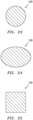
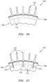
- one or more or each of the disk mounts 188 may be configured with a circular cross-sectional geometry when viewed in a plane perpendicular to the axial centerline 102.
- one or more or each of the disk mounts 188 may be configured with an elongated (e.g., oval, elliptical, etc.) cross-sectional geometry when viewed in a plane perpendicular to the axial centerline 102.
- referring to FIG. 23 one or more or each of the disk mounts 188 may be configured with a circular cross-sectional geometry when viewed in a plane perpendicular to the axial centerline 102.
- an elongated cross-sectional geometry when viewed in a plane perpendicular to the axial centerline 102.
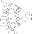
- some of the internal vanes 234 may be connected to the first web 184A and may axially engage the second web 184B, and the remaining internal vanes 234 may be connected to the second web 184B and may axially engage the first web 184A.
- the vanes 234 connected to the first web 184A may be interposed with the vanes 234 connected to the second web 184B.
- One or more or each of the internal vanes 234 may be formed integral with a respective one of the rotor disks 180 as described above.
- the rotor disk 180 and the respective internal vanes 234 may be formed together from a single mass of material.
- the internal vanes 234 may be permanently bonded to the rotor disk 180 using one or more of the techniques described above, for example.
- one or more of the internal vanes 234 may be removably mounted to the rotor disk assembly 106.
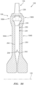
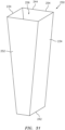
- the internal vanes 234 may be configured into a plurality of tubular structures 250 that are removably attached to one or each of the rotor disks 180.
- the internal vanes 234 are interposed with the disk mounts 188 in a similar fashion as described above.
- a respective one of the disk mounts 188 may be located circumferentially between each circumferentially neighboring pair of the tubular structures 250.
- a respective one of the disk mounts 188 may project axially through the first sidewall 252 and the second sidewall 254 of each tubular structure 250.
- the disk mounts 188 may only be positioned in the gap between neighboring tubular structures 250.
- the disk mounts 188 may only be aligned with and, thus, project axially through the tubular structures 250.
- the axial first side and the first sidewall 252 of the tubular structure 250 is located at (e.g., abutted axially against or otherwise axially engaged with) the first web 184A.
- the axial second side and the second sidewall 254 of the tubular structure 250 is located at (e.g., abutted axially against or otherwise axially engaged with) the second web 184B.
- a second flange located at the distal radial outer end of the tubular structure 250.
- This second flange projects axially (in the first axial direction) into a second groove 266 in the second rotor disk 180B; e.g., in the second web 184B.
- each of the distal ends 316, 318 may be located at (e.g., on, adjacent or proximate) and may thereby form a portion of the rotor blade tip 170.
- one or each of the distal ends 316, 318 may be located radially inward of the rotor blade tip 170.
- one or more third sheets of material 326 are layered over the second sheet(s) of material 320 to form another (e.g., lateral side) portion of the rotor blade mount 108 (e.g., 112, 114 and/or 116); e.g., see FIG. 39 .
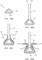
- the third sheets of material 326 may be configured from one or more layers of woven material, or one or one or more layers of braided material. Exemplary embodiments of the third sheets of material 326 are illustrated in FIG. 38D .
- Each third sheet of material 326 of FIG. 38D extends longitudinally along a length thereof between opposing distal ends 328 and 330, where the distal ends 328 and 330 are arranged on a common side of the attachment preform 304.
- the first distal end 328 of FIG. 39 is configured to be aligned with (or proximate to) the platform lateral side 130 and/or the overhang 134.
- the second distal end 330 is configured to be aligned with (e.g., overlap), or be adjacent to, the attachment pressure surface 154.
- the third sheet(s) of material 326 may thereby provide a reinforced interface between the mount attachment 116, the mount neck 114 and the mount platform 112 and its overhang 134.
- the third sheet of material 326 may be stitched or sewn or connected via other techniques with similar or complementary fibers in order to connect one or more surfaces or regions, for example, at the distal ends 328 and 330. In one embodiment, the location of this connection would be in the thinned region 337 below the platform 112.
- one or more fourth sheets of material 332 are layered over the second sheet(s) of material 320 to form another (e.g., lateral side) portion of the rotor blade mount 108 (e.g., 112, 114 and/or 116); e.g., see FIG. 39 .
- the fourth sheets of material 332 may be configured from one or more layers of woven material, or one or one or more layers of braided material. Exemplary embodiments of the fourth sheets of material 332 are illustrated in FIG. 38D . Each fourth sheet of material 332 of FIG.
- the 38D extends longitudinally along a length thereof between opposing distal ends 334 and 336, where the distal ends 334 and 336 are arranged on a common side of the attachment preform 304 that is opposite the side of the third sheet(s) of material 326.
- the first distal end 334 of FIG. 39 is configured to be aligned with (or proximate to) the platform lateral side 132 and/or the overhang 136.
- the second distal end 336 is configured to be aligned with (e.g., overlap), or be adjacent to, the attachment pressure surface 156.
- the fourth sheet(s) of material 332 may thereby provide a reinforced interface between the mount attachment 116, the mount neck 114 and the mount platform 112 and its overhang 136.
- the fourth sheet of material 332 may be stitched or sewn or connected via other techniques with similar or complementary fibers in order to connect one or more surfaces or regions, for example, at the distal ends 334 and 336. In one embodiment the location of this connection would be in the thinned region 337 below the platform 112.
- the various materials 306, 308, 314, 320, 326 and 332 are bonded together to form a monolithic rotor blade body.
- the matrix may be cured.
- the various materials 306, 308, 314, 320, 326 and 332 or some of those materials may be impregnated with / disposed within the matrix and then cured.
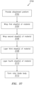
- the method 3700 may include additional step other than those described above.
- the method 3700 may include one or more surface machining steps and/or one or more coating steps in order to provide the final rotor blade 104.
- the foregoing materials 306, 308, 314, 320, 326, 332 and any fibers used for stitching, sewing, etc. may be selected to be a common material; e.g., have the same material makeup. Alternatively, one or more of the foregoing materials 306, 308, 314, 320, 326, 332 and any fibers used for stitching, sewing, etc. may be different than one or more of the other materials 306, 308, 314, 320, 326 and 332.
Landscapes
- Engineering & Computer Science (AREA)
- Mechanical Engineering (AREA)
- General Engineering & Computer Science (AREA)
- Chemical & Material Sciences (AREA)
- Materials Engineering (AREA)
- Ceramic Engineering (AREA)
- Composite Materials (AREA)
- Turbine Rotor Nozzle Sealing (AREA)
- Structures Of Non-Positive Displacement Pumps (AREA)
Applications Claiming Priority (8)
| Application Number | Priority Date | Filing Date | Title |
|---|---|---|---|
| US202062962640P | 2020-01-17 | 2020-01-17 | |
| US202062962628P | 2020-01-17 | 2020-01-17 | |
| US202062962635P | 2020-01-17 | 2020-01-17 | |
| US202062962620P | 2020-01-17 | 2020-01-17 | |
| US202062962636P | 2020-01-17 | 2020-01-17 | |
| US16/796,205 US11286781B2 (en) | 2020-01-17 | 2020-02-20 | Multi-disk bladed rotor assembly for rotational equipment |
| EP21152129.9A EP3851635B1 (fr) | 2020-01-17 | 2021-01-18 | Ensemble rotor pour un moteur à turbine à gaz |
| EP23172441.0A EP4234516B1 (fr) | 2020-01-17 | 2021-01-18 | Agencement de rotor pour un moteur à turbine à gaz |
Related Parent Applications (2)
| Application Number | Title | Priority Date | Filing Date |
|---|---|---|---|
| EP23172441.0A Division EP4234516B1 (fr) | 2020-01-17 | 2021-01-18 | Agencement de rotor pour un moteur à turbine à gaz |
| EP21152129.9A Division EP3851635B1 (fr) | 2020-01-17 | 2021-01-18 | Ensemble rotor pour un moteur à turbine à gaz |
Publications (2)
| Publication Number | Publication Date |
|---|---|
| EP4534509A2 true EP4534509A2 (fr) | 2025-04-09 |
| EP4534509A3 EP4534509A3 (fr) | 2025-06-18 |
Family
ID=74187182
Family Applications (3)
| Application Number | Title | Priority Date | Filing Date |
|---|---|---|---|
| EP25159515.3A Pending EP4534509A3 (fr) | 2020-01-17 | 2021-01-18 | Ensemble rotor à aubes à disques multiples pour équipement rotatif |
| EP23172441.0A Active EP4234516B1 (fr) | 2020-01-17 | 2021-01-18 | Agencement de rotor pour un moteur à turbine à gaz |
| EP21152129.9A Active EP3851635B1 (fr) | 2020-01-17 | 2021-01-18 | Ensemble rotor pour un moteur à turbine à gaz |
Family Applications After (2)
| Application Number | Title | Priority Date | Filing Date |
|---|---|---|---|
| EP23172441.0A Active EP4234516B1 (fr) | 2020-01-17 | 2021-01-18 | Agencement de rotor pour un moteur à turbine à gaz |
| EP21152129.9A Active EP3851635B1 (fr) | 2020-01-17 | 2021-01-18 | Ensemble rotor pour un moteur à turbine à gaz |
Country Status (2)
| Country | Link |
|---|---|
| US (1) | US11286781B2 (fr) |
| EP (3) | EP4534509A3 (fr) |
Families Citing this family (1)
| Publication number | Priority date | Publication date | Assignee | Title |
|---|---|---|---|---|
| CN114542191A (zh) * | 2022-03-28 | 2022-05-27 | 南昌航空大学 | 一种具有高承载导流结构的双辐板涡轮盘 |
Family Cites Families (58)
| Publication number | Priority date | Publication date | Assignee | Title |
|---|---|---|---|---|
| US1362074A (en) * | 1919-05-03 | 1920-12-14 | British Westinghouse Electric | Turbine |
| US2401826A (en) * | 1941-11-21 | 1946-06-11 | Dehavilland Aircraft | Turbine |
| US2657008A (en) * | 1947-08-07 | 1953-10-27 | Atkinson Joseph | Turbine or like rotor |
| US2641440A (en) * | 1947-11-18 | 1953-06-09 | Chrysler Corp | Turbine blade with cooling means and carrier therefor |
| US2819869A (en) * | 1950-05-02 | 1958-01-14 | Jr Andre J Meyer | Mounting arrangement for turbine or compressor blading |
| US2918252A (en) * | 1954-12-24 | 1959-12-22 | Rolls Royce | Turbine rotor disc structure |
| FR1245518A (fr) * | 1957-04-19 | 1960-11-10 | Perfectionnements apportés aux turbines à fluide gazeux chaud | |
| GB848465A (en) | 1957-06-14 | 1960-09-14 | Napier & Son Ltd | Rotors of multi-stage axial flow compressors or turbines |
| US2988325A (en) * | 1957-07-18 | 1961-06-13 | Rolls Royce | Rotary fluid machine with means supplying fluid to rotor blade passages |
| US2994507A (en) * | 1959-01-23 | 1961-08-01 | Westinghouse Electric Corp | Blade locking structure |
| GB1036739A (en) * | 1965-04-02 | 1966-07-20 | Rolls Royce | Rotor and blade assemblies |
| US3742706A (en) * | 1971-12-20 | 1973-07-03 | Gen Electric | Dual flow cooled turbine arrangement for gas turbine engines |
| US3832090A (en) * | 1972-12-01 | 1974-08-27 | Avco Corp | Air cooling of turbine blades |
| SE375583B (fr) * | 1973-05-22 | 1975-04-21 | United Turbine Ab & Co | |
| US3982852A (en) * | 1974-11-29 | 1976-09-28 | General Electric Company | Bore vane assembly for use with turbine discs having bore entry cooling |
| US4102603A (en) | 1975-12-15 | 1978-07-25 | General Electric Company | Multiple section rotor disc |
| US4097194A (en) * | 1976-03-22 | 1978-06-27 | The United States Of America As Represented By The Administrator Of The National Aeronautics And Space Administration | Redundant disc |
| US4098559A (en) | 1976-07-26 | 1978-07-04 | United Technologies Corporation | Paired blade assembly |
| US4171930A (en) * | 1977-12-28 | 1979-10-23 | General Electric Company | U-clip for boltless blade retainer |
| US4595340A (en) * | 1984-07-30 | 1986-06-17 | General Electric Company | Gas turbine bladed disk assembly |
| FR2608674B1 (fr) | 1986-12-17 | 1991-04-19 | Snecma | Roue de turbine a aubes ceramique |
| DE3718678A1 (de) * | 1987-06-04 | 1988-12-22 | Mtu Muenchen Gmbh | Fasertechnische verdichterschaufel |
| FR2666623B1 (fr) * | 1990-09-11 | 1993-05-07 | Turbomeca | Roue de turbomachine a pales rapportees. |
| US5135354A (en) | 1990-09-14 | 1992-08-04 | United Technologies Corporation | Gas turbine blade and disk |
| US5197857A (en) * | 1991-06-06 | 1993-03-30 | General Electric Company | Multiple rotor disk assembly |
| US5435694A (en) * | 1993-11-19 | 1995-07-25 | General Electric Company | Stress relieving mount for an axial blade |
| US5961287A (en) | 1997-09-25 | 1999-10-05 | United Technologies Corporation | Twin-web rotor disk |
| US6267553B1 (en) | 1999-06-01 | 2001-07-31 | Joseph C. Burge | Gas turbine compressor spool with structural and thermal upgrades |
| US6213720B1 (en) * | 1999-06-11 | 2001-04-10 | Alliedsignal, Inc. | High strength composite reinforced turbomachinery disk |
| DE10159670A1 (de) | 2001-12-05 | 2003-06-18 | Rolls Royce Deutschland | Wirbelgleichrichter im Hochdruckverdichter einer Gasturbine |
| DE10326719A1 (de) | 2003-06-06 | 2004-12-23 | Rolls-Royce Deutschland Ltd & Co Kg | Verdichterschaufelfuß für Triebwerksschaufeln von Flugzeugtriebwerken |
| US7278821B1 (en) | 2004-11-04 | 2007-10-09 | General Electric Company | Methods and apparatus for assembling gas turbine engines |
| GB0815475D0 (en) | 2008-08-27 | 2008-10-01 | Rolls Royce Plc | A blade |
| US8435008B2 (en) * | 2008-10-17 | 2013-05-07 | United Technologies Corporation | Turbine blade including mistake proof feature |
| US8231354B2 (en) | 2009-12-15 | 2012-07-31 | Siemens Energy, Inc. | Turbine engine airfoil and platform assembly |
| GB201000982D0 (en) * | 2010-01-22 | 2010-03-10 | Rolls Royce Plc | A rotor disc |
| US8636470B2 (en) * | 2010-10-13 | 2014-01-28 | Honeywell International Inc. | Turbine blades and turbine rotor assemblies |
| FR2976968B1 (fr) | 2011-06-21 | 2015-06-05 | Snecma | Piece de turbomachine formant redresseur de compresseur ou distributeur de turbine et procede pour sa fabrication |
| US9212560B2 (en) | 2011-06-30 | 2015-12-15 | United Technologies Corporation | CMC blade with integral 3D woven platform |
| US9598967B2 (en) | 2012-12-18 | 2017-03-21 | United Technologies Corporation | Airfoil member and composite platform having contoured endwall |
| FR3008131B1 (fr) | 2013-07-02 | 2016-09-30 | Snecma | Etage de turbine ou de compresseur comprenant une piece d'interface en materiau ceramique |
| US10145245B2 (en) | 2013-09-24 | 2018-12-04 | United Technologies Corporation | Bonded multi-piece gas turbine engine component |
| US10458257B2 (en) * | 2013-12-23 | 2019-10-29 | Safran Aircraft Engines | Blade comprising a shank, provided with a depressed portion |
| US9932902B2 (en) | 2014-07-15 | 2018-04-03 | United Technologies Corporation | Turbine section support for a gas turbine engine |
| UY36272A (es) | 2014-08-13 | 2016-02-29 | Eolas Therapeutics Inc | Difluoropirrolidinas como moduladores de los receptores de orexinas |
| US20200300174A1 (en) * | 2014-08-15 | 2020-09-24 | General Electric Company | Power train architectures with low-loss lubricant bearings and low-density materials |
| EP3239469B1 (fr) | 2014-11-20 | 2019-01-09 | Rolls-Royce North American Technologies, Inc. | Lames composites pour moteurs à turbine à gaz |
| KR101643476B1 (ko) * | 2014-12-24 | 2016-07-27 | 두산중공업 주식회사 | 터빈의 교체용 버켓 조립체 및 이의 교체방법 |
| US9970302B2 (en) * | 2015-06-15 | 2018-05-15 | General Electric Company | Hot gas path component trailing edge having near wall cooling features |
| US10273813B2 (en) * | 2015-10-29 | 2019-04-30 | General Electric Company | Ceramic matrix composite component and process of producing a ceramic matrix composite component |
| US10814445B2 (en) | 2016-05-09 | 2020-10-27 | Raytheon Technologies Corporation | Airfoil machining |
| US10577939B2 (en) | 2016-11-01 | 2020-03-03 | Rolls-Royce Corporation | Turbine blade with three-dimensional CMC construction elements |
| GB2559325A (en) * | 2017-01-25 | 2018-08-08 | Rolls Royce Plc | Bladed disc and method of manufacturing the same |
| US11168702B2 (en) | 2017-08-10 | 2021-11-09 | Raytheon Technologies Corporation | Rotating airfoil with tip pocket |
| US10533425B2 (en) | 2017-12-28 | 2020-01-14 | United Technologies Corporation | Doublet vane assembly for a gas turbine engine |
| US10767498B2 (en) | 2018-04-03 | 2020-09-08 | Rolls-Royce High Temperature Composites Inc. | Turbine disk with pinned platforms |
| US10787917B2 (en) | 2018-05-04 | 2020-09-29 | Rolls-Royce North American Technologies Inc. | Multi-piece turbine disk for ceramic matrix composite components |
| US10934863B2 (en) * | 2018-11-13 | 2021-03-02 | Rolls-Royce Corporation | Turbine wheel assembly with circumferential blade attachment |
-
2020
- 2020-02-20 US US16/796,205 patent/US11286781B2/en active Active
-
2021
- 2021-01-18 EP EP25159515.3A patent/EP4534509A3/fr active Pending
- 2021-01-18 EP EP23172441.0A patent/EP4234516B1/fr active Active
- 2021-01-18 EP EP21152129.9A patent/EP3851635B1/fr active Active
Also Published As
| Publication number | Publication date |
|---|---|
| US20210222558A1 (en) | 2021-07-22 |
| EP4234516A3 (fr) | 2023-09-13 |
| EP4534509A3 (fr) | 2025-06-18 |
| EP4234516B1 (fr) | 2025-03-26 |
| EP3851635B1 (fr) | 2023-06-14 |
| EP3851635A3 (fr) | 2021-07-28 |
| US11286781B2 (en) | 2022-03-29 |
| EP4234516A2 (fr) | 2023-08-30 |
| EP3851635A2 (fr) | 2021-07-21 |
Similar Documents
| Publication | Publication Date | Title |
|---|---|---|
| US11572796B2 (en) | Multi-material vane for a gas turbine engine | |
| US9915154B2 (en) | Ceramic matrix composite airfoil structures for a gas turbine engine | |
| WO2013141939A2 (fr) | Procédé de fabrication de composant de turbomachine, de profil aérodynamique, et de turbine à gaz | |
| EP3851640B1 (fr) | Ensembles de rotor pour un moteur à turbine à gaz | |
| EP3851636B1 (fr) | Ensembles de rotor pour un moteur à turbine à gaz | |
| EP4234516B1 (fr) | Agencement de rotor pour un moteur à turbine à gaz | |
| EP3851638B1 (fr) | Ensemble de rotor pour un moteur à turbine à gaz | |
| EP3851639B1 (fr) | Aube rotorique et ensemble rotor pour un moteur à turbine à gaz | |
| EP3851637B1 (fr) | Ensemble rotor pour un moteur à turbine à gaz | |
| EP3896254B1 (fr) | Aube multi-matériaux pour un moteur à turbine à gaz | |
| EP3851641B1 (fr) | Dispositif pour un ensemble de rotor avec un axe de rotation et procédé de fabrication | |
| EP4083390B1 (fr) | Ensemble joint à brosse double | |
| US12473835B2 (en) | Vane array structure with recessed stator vanes |
Legal Events
| Date | Code | Title | Description |
|---|---|---|---|
| PUAI | Public reference made under article 153(3) epc to a published international application that has entered the european phase |
Free format text: ORIGINAL CODE: 0009012 |
|
| STAA | Information on the status of an ep patent application or granted ep patent |
Free format text: STATUS: THE APPLICATION HAS BEEN PUBLISHED |
|
| AC | Divisional application: reference to earlier application |
Ref document number: 3851635 Country of ref document: EP Kind code of ref document: P Ref document number: 4234516 Country of ref document: EP Kind code of ref document: P |
|
| AK | Designated contracting states |
Kind code of ref document: A2 Designated state(s): AL AT BE BG CH CY CZ DE DK EE ES FI FR GB GR HR HU IE IS IT LI LT LU LV MC MK MT NL NO PL PT RO RS SE SI SK SM TR |
|
| REG | Reference to a national code |
Ref country code: DE Ref legal event code: R079 Free format text: PREVIOUS MAIN CLASS: C04B0035800000 Ipc: F01D0005300000 |
|
| PUAL | Search report despatched |
Free format text: ORIGINAL CODE: 0009013 |
|
| AK | Designated contracting states |
Kind code of ref document: A3 Designated state(s): AL AT BE BG CH CY CZ DE DK EE ES FI FR GB GR HR HU IE IS IT LI LT LU LV MC MK MT NL NO PL PT RO RS SE SI SK SM TR |
|
| RIC1 | Information provided on ipc code assigned before grant |
Ipc: C04B 35/80 20060101ALN20250512BHEP Ipc: F01D 5/28 20060101ALN20250512BHEP Ipc: F01D 5/30 20060101AFI20250512BHEP |
|
| STAA | Information on the status of an ep patent application or granted ep patent |
Free format text: STATUS: REQUEST FOR EXAMINATION WAS MADE |
|
| 17P | Request for examination filed |
Effective date: 20251218 |