EP4521039A1 - Kühlvorrichtung, umgebungsformungsvorrichtung und kühlverfahren - Google Patents
Kühlvorrichtung, umgebungsformungsvorrichtung und kühlverfahren Download PDFInfo
- Publication number
- EP4521039A1 EP4521039A1 EP24198673.6A EP24198673A EP4521039A1 EP 4521039 A1 EP4521039 A1 EP 4521039A1 EP 24198673 A EP24198673 A EP 24198673A EP 4521039 A1 EP4521039 A1 EP 4521039A1
- Authority
- EP
- European Patent Office
- Prior art keywords
- degree
- temperature
- compressor
- refrigeration
- refrigerant
- Prior art date
- Legal status (The legal status is an assumption and is not a legal conclusion. Google has not performed a legal analysis and makes no representation as to the accuracy of the status listed.)
- Pending
Links
Images




Classifications
-
- F—MECHANICAL ENGINEERING; LIGHTING; HEATING; WEAPONS; BLASTING
- F25—REFRIGERATION OR COOLING; COMBINED HEATING AND REFRIGERATION SYSTEMS; HEAT PUMP SYSTEMS; MANUFACTURE OR STORAGE OF ICE; LIQUEFACTION SOLIDIFICATION OF GASES
- F25B—REFRIGERATION MACHINES, PLANTS OR SYSTEMS; COMBINED HEATING AND REFRIGERATION SYSTEMS; HEAT PUMP SYSTEMS
- F25B1/00—Compression machines, plants or systems with non-reversible cycle
-
- F—MECHANICAL ENGINEERING; LIGHTING; HEATING; WEAPONS; BLASTING
- F24—HEATING; RANGES; VENTILATING
- F24F—AIR-CONDITIONING; AIR-HUMIDIFICATION; VENTILATION; USE OF AIR CURRENTS FOR SCREENING
- F24F11/00—Control or safety arrangements
- F24F11/70—Control systems characterised by their outputs; Constructional details thereof
- F24F11/80—Control systems characterised by their outputs; Constructional details thereof for controlling the temperature of the supplied air
- F24F11/83—Control systems characterised by their outputs; Constructional details thereof for controlling the temperature of the supplied air by controlling the supply of heat-exchange fluids to heat-exchangers
- F24F11/84—Control systems characterised by their outputs; Constructional details thereof for controlling the temperature of the supplied air by controlling the supply of heat-exchange fluids to heat-exchangers using valves
-
- F—MECHANICAL ENGINEERING; LIGHTING; HEATING; WEAPONS; BLASTING
- F24—HEATING; RANGES; VENTILATING
- F24F—AIR-CONDITIONING; AIR-HUMIDIFICATION; VENTILATION; USE OF AIR CURRENTS FOR SCREENING
- F24F5/00—Air-conditioning systems or apparatus not covered by F24F1/00 or F24F3/00, e.g. using solar heat or combined with household units such as an oven or water heater
- F24F5/0007—Air-conditioning systems or apparatus not covered by F24F1/00 or F24F3/00, e.g. using solar heat or combined with household units such as an oven or water heater cooling apparatus specially adapted for use in air-conditioning
- F24F5/001—Compression cycle type
-
- F—MECHANICAL ENGINEERING; LIGHTING; HEATING; WEAPONS; BLASTING
- F25—REFRIGERATION OR COOLING; COMBINED HEATING AND REFRIGERATION SYSTEMS; HEAT PUMP SYSTEMS; MANUFACTURE OR STORAGE OF ICE; LIQUEFACTION SOLIDIFICATION OF GASES
- F25B—REFRIGERATION MACHINES, PLANTS OR SYSTEMS; COMBINED HEATING AND REFRIGERATION SYSTEMS; HEAT PUMP SYSTEMS
- F25B40/00—Subcoolers, desuperheaters or superheaters
- F25B40/02—Subcoolers
-
- F—MECHANICAL ENGINEERING; LIGHTING; HEATING; WEAPONS; BLASTING
- F25—REFRIGERATION OR COOLING; COMBINED HEATING AND REFRIGERATION SYSTEMS; HEAT PUMP SYSTEMS; MANUFACTURE OR STORAGE OF ICE; LIQUEFACTION SOLIDIFICATION OF GASES
- F25B—REFRIGERATION MACHINES, PLANTS OR SYSTEMS; COMBINED HEATING AND REFRIGERATION SYSTEMS; HEAT PUMP SYSTEMS
- F25B41/00—Fluid-circulation arrangements
- F25B41/20—Disposition of valves, e.g. of on-off valves or flow control valves
-
- F—MECHANICAL ENGINEERING; LIGHTING; HEATING; WEAPONS; BLASTING
- F25—REFRIGERATION OR COOLING; COMBINED HEATING AND REFRIGERATION SYSTEMS; HEAT PUMP SYSTEMS; MANUFACTURE OR STORAGE OF ICE; LIQUEFACTION SOLIDIFICATION OF GASES
- F25B—REFRIGERATION MACHINES, PLANTS OR SYSTEMS; COMBINED HEATING AND REFRIGERATION SYSTEMS; HEAT PUMP SYSTEMS
- F25B49/00—Arrangement or mounting of control or safety devices
- F25B49/02—Arrangement or mounting of control or safety devices for compression type machines, plants or systems
-
- F—MECHANICAL ENGINEERING; LIGHTING; HEATING; WEAPONS; BLASTING
- F25—REFRIGERATION OR COOLING; COMBINED HEATING AND REFRIGERATION SYSTEMS; HEAT PUMP SYSTEMS; MANUFACTURE OR STORAGE OF ICE; LIQUEFACTION SOLIDIFICATION OF GASES
- F25B—REFRIGERATION MACHINES, PLANTS OR SYSTEMS; COMBINED HEATING AND REFRIGERATION SYSTEMS; HEAT PUMP SYSTEMS
- F25B2400/00—Component parts or details not otherwise provided for in this subclass
- F25B2400/04—Refrigeration circuit bypassing means
- F25B2400/0409—Refrigeration circuit bypassing means for evaporators
-
- F—MECHANICAL ENGINEERING; LIGHTING; HEATING; WEAPONS; BLASTING
- F25—REFRIGERATION OR COOLING; COMBINED HEATING AND REFRIGERATION SYSTEMS; HEAT PUMP SYSTEMS; MANUFACTURE OR STORAGE OF ICE; LIQUEFACTION SOLIDIFICATION OF GASES
- F25B—REFRIGERATION MACHINES, PLANTS OR SYSTEMS; COMBINED HEATING AND REFRIGERATION SYSTEMS; HEAT PUMP SYSTEMS
- F25B2400/00—Component parts or details not otherwise provided for in this subclass
- F25B2400/04—Refrigeration circuit bypassing means
- F25B2400/0411—Refrigeration circuit bypassing means for expansion valves or capillary tubes
-
- F—MECHANICAL ENGINEERING; LIGHTING; HEATING; WEAPONS; BLASTING
- F25—REFRIGERATION OR COOLING; COMBINED HEATING AND REFRIGERATION SYSTEMS; HEAT PUMP SYSTEMS; MANUFACTURE OR STORAGE OF ICE; LIQUEFACTION SOLIDIFICATION OF GASES
- F25B—REFRIGERATION MACHINES, PLANTS OR SYSTEMS; COMBINED HEATING AND REFRIGERATION SYSTEMS; HEAT PUMP SYSTEMS
- F25B2700/00—Sensing or detecting of parameters; Sensors therefor
- F25B2700/19—Pressures
- F25B2700/193—Pressures of the compressor
- F25B2700/1933—Suction pressures
-
- F—MECHANICAL ENGINEERING; LIGHTING; HEATING; WEAPONS; BLASTING
- F25—REFRIGERATION OR COOLING; COMBINED HEATING AND REFRIGERATION SYSTEMS; HEAT PUMP SYSTEMS; MANUFACTURE OR STORAGE OF ICE; LIQUEFACTION SOLIDIFICATION OF GASES
- F25B—REFRIGERATION MACHINES, PLANTS OR SYSTEMS; COMBINED HEATING AND REFRIGERATION SYSTEMS; HEAT PUMP SYSTEMS
- F25B2700/00—Sensing or detecting of parameters; Sensors therefor
- F25B2700/21—Temperatures
- F25B2700/2115—Temperatures of a compressor or the drive means therefor
- F25B2700/21151—Temperatures of a compressor or the drive means therefor at the suction side of the compressor
Definitions
- the changing unit 105 changes the target value of the degree of superheat with respect to the saturation temperature corresponding to the suction pressure of the compressor 1 according to the refrigeration request degree, but alternatively, the target value of the degree of superheat may be changed according to the opening degree of the expansion valve 3.
- the target value of the degree of superheat changes according to the opening degree of the expansion valve 3, and the valve opening degree of the flow rate adjusting valve 11 is adjusted accordingly. That is, since the opening degree of the expansion valve 3 is adjusted to the opening degree according to the refrigeration request degree, the target value of the degree of superheat is changed according to the opening degree of the expansion valve 3, whereby the valve opening degree of flow rate adjusting valve 11 is adjusted to the opening degree according to the refrigeration request degree.
- the upper limit value of the superheating degree target value changes according to the in-freezer temperature, but is not limited thereto.
- a region where the upper limit value of the superheating degree target value decreases as the outlet temperature of the evaporator 4 or the evaporation temperature of the refrigerant decreases, instead of the in-freezer temperature, may be provided.
- the upper limit value of the superheating degree target value may be set to be smaller as these temperatures are lower. Even in these cases, the cooling effect of the compressor 1 can be easily obtained.
- the upper limit value of the superheating degree target value may be set to decrease as the detection temperature by the bypass temperature detector 21 (that is, the temperature on the outlet side of the flow rate adjusting valve 11 in the bypass flow path 16) decreases, instead of the in-freezer temperature. That is, since the detection temperature of the bypass temperature detector 21 depends on the suction pressure to the compressor 1 (or low pressure in the main circuit 15), the detection temperature of the bypass temperature detector 21 decreases as the opening degree of the expansion valve 3 decreases.
- the upper limit value of the superheating degree target value may be set to decrease when a value obtained as a result of predetermined processing (for example, average processing) of the plurality of temperatures decreases.
- the superheating degree calculation unit 103 derives a difference value between the temperature detected by the suction temperature detector 22 and the temperature detected by the bypass temperature detector 21 as the degree of superheat of the refrigerant suctioned into the compressor 1, but the present embodiment is not limited thereto.
- the bypass temperature detector 21 may be omitted, and the pressure detector 31 that detects the pressure of the refrigerant suctioned into the compressor 1 may be provided.
- the superheating degree calculation unit 103 may derive a difference value between the temperature detected by the suction temperature detector 22 and the saturated vapor temperature corresponding to the pressure detected by the pressure detector 31 as the degree of superheat of the suction refrigerant.
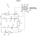
- the refrigeration apparatus 10 includes a hot gas bypass flow path 17. Note that, here, the same components as those of the first embodiment are denoted by the same reference numerals, and the detailed description thereof will be omitted.
- the hot gas bypass flow path 17 is a flow path through which a part of the refrigerant discharged from the compressor 1 is suctioned into the compressor 1 without passing through the condenser 2, the expansion valve 3, and the evaporator 4.
- One end of the hot gas bypass flow path 17 is connected to a portion of the main circuit 15 between the compressor 1 and the condenser 2.
- the other end of the hot gas bypass flow path 17 is connected to a portion of the main circuit 15 between the evaporator 4 and the compressor 1.
- the hot gas bypass flow path 17 is provided with a hot gas valve 12 including a mechanical expansion valve.
- the hot gas valve 12 is always opened in a state of being set to a predetermined opening degree.
- the hot gas valve 12 is not limited thereto and may be controlled to open and close by the controller 100 as illustrated in Figs. 7 and 8 . That is, the hot gas valve 12 may be controlled to be opened when the suction pressure of the compressor 1 can be equal to or lower than the set pressure, such as when the expansion valve 3 is closed (or the opening degree becomes very small), and to be closed otherwise.
- the set pressure may be a pressure determined from design conditions of the compressor 1 set as a range in which the compressor 1 can be stably operated.
- the hot gas control unit 106 of the controller 100 controls the hot gas valve 12 so that the suction pressure of the compressor 1 does not become equal to or lower than the set pressure. That is, when the opening degree of the expansion valve 3 decreases, the suction pressure of the compressor 1 decreases accordingly, and thus, when the opening degree of the expansion valve 3 is closed (or made very small) to reduce the refrigeration capacity as much as possible, the suction pressure of the compressor 1 may excessively decrease, and there is a possibility that stable operation cannot be performed. Accordingly, when the suction pressure is likely to become equal to or lower than the set pressure, the hot gas control unit 106 opens the hot gas valve 12.
- the suction pressure can be prevented from becoming equal to or lower than the set pressure. Therefore, it is possible to minimize the refrigeration capacity of the evaporator 4 as much as possible while ensuring the stable operation of the compressor 1.
- the hot gas valve 12 may be configured by an electronic expansion valve.
- the hot gas control unit 106 is configured to control the opening degree of the hot gas valve 12.
- the hot gas control unit 106 may perform control of adjusting the opening degree of the hot gas valve 12 in conjunction with the opening degree control of the expansion valve 3 by the expansion control unit 102 or according to the refrigeration request degree.
- the hot gas control unit 106 performs control to open the hot gas valve 12 at least when the expansion valve 3 is closed.
- the refrigeration capacity of the evaporator 4 can be reduced as much as possible.
- the hot gas valve 12 is controlled according to the refrigeration request degree, the hot gas valve 12 is controlled so that the opening degree of the hot gas valve 12 becomes larger as the refrigeration request degree decreases.
- the suction pressure of the compressor 1 can be secured. Further, in a case where the pressure sensor 31 that detects the pressure of the refrigerant suctioned into the compressor 1 is provided, it is also possible to control the hot gas valve 12 so that the suction pressure of the compressor 1 does not decrease to a predetermined pressure or less.
- Fig. 9 illustrates a third embodiment. Note that, here, the same components as those of the first or second embodiment are denoted by the same reference numerals, and the detailed description thereof will be omitted.
- the third embodiment is an example in which the refrigeration apparatus 10 is applied to an environment forming apparatus 50 such as an environment testing apparatus.
- the refrigeration apparatus 10 may be any of the refrigeration apparatuses according to the first embodiment and the second embodiment.
- the environment forming apparatus 50 includes an environment chamber 51 and adjusts the inside of the environment chamber 51 to a predetermined temperature environment.
- the environment forming apparatus 50 further includes an air conditioning chamber 52 for generating air whose temperature is adjusted, and the evaporator 4 of the refrigeration apparatus 10 is disposed in the air conditioning chamber 52.
- a heater 54 for heating the air and a blower 55 for blowing out the temperature-adjusted air to the environment chamber 51 are disposed on the downstream side of the evaporator 4.
- the sensor 121 for detecting a room temperature is installed in the environment chamber 51.
- the input device 122 is used to input a set temperature of the temperature in the environment chamber 51. Note that, in the present embodiment, the "in-freezer temperature" in the first and second embodiments is replaced with the "room temperature”. That is, the sensor 121 detects the air temperature in the room to which the air cooled by the evaporator 4 is supplied.
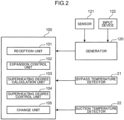
- the generator 120 calculates the refrigeration request degree using the detection temperature by the sensor 121 and the set temperature from the input device 122.
- the output of the heater 54 is controlled based on the detection temperature by the sensor 121 and the set temperature from the input device 122. That is, the expansion valve 3 of the refrigeration apparatus 10 is controlled based on the refrigeration request degree, so that a predetermined refrigeration capacity is exhibited. At this time, since the detection temperature by the sensor 121 may be lower than the set temperature, the room temperature is finely adjusted by the heater 54. Thus, if excessive cooling by the refrigeration apparatus 10 can be suppressed, not only the power of the refrigeration apparatus 10 can be suppressed, but also the power of the heater 54 can be suppressed.
- the changing unit 105 lowers the target value of the degree of superheat, and thus the flow rate adjusting valve 11 is controlled so that the opening degree of the flow rate adjusting valve 11 becomes larger accordingly. Accordingly, the flow rate of the refrigerant flowing into the evaporator 4 can be further reduced under the opening degree of the expansion valve 3 controlled by the expansion control unit 102. Therefore, as compared with a case where the target value of the degree of superheat is fixed, the refrigeration capacity exhibited by the evaporator 4 can be reduced, so that the power of the heater 54 can also be suppressed, and further energy saving can be achieved. Note that the heater 54 can be omitted.
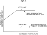
- the upper limit value of the target value of the degree of superheat is set to decrease as the room temperature decreases.
- the refrigeration request degree is 100%
- the lower the room temperature is, the more the expansion valve 3 tends to be throttled and the more the flow rate adjusting valve 11 is opened.
- the flow rate of the refrigerant flowing into the evaporator 4 is further reduced, so that the cooling capacity of the evaporator 4 can be further reduced. Therefore, since the output of the heater 54 can be suppressed, energy saving of the environment forming apparatus 50 can be achieved.
- the cooling effect of the compressor can be further enhanced.
- the evaporation temperature needs to be lower as compared to a case where the temperature of the room to be cooled is high with respect to the same refrigeration request degree, so that the expansion valve tends to be throttled.
- the refrigerant circulation flow rate tends to decrease as the temperature of the room to be cooled decreases, so that it is difficult to obtain the cooling effect of the compressor.
- the flow rate adjusting valve is further opened by setting the upper limit value of the target value of the degree of superheat to decrease as the temperature of the room to be cooled decreases. This makes it possible to easily obtain the cooling effect of the compressor even when the expansion valve is in a throttled state. The same applies to a case where the outlet temperature of the evaporator and the evaporation temperature of the refrigerant decrease.
- the temperature on the outlet side of the flow rate adjusting valve depends on the suction pressure to the compressor (or low pressure of the refrigeration circuit), this temperature decreases as the opening degree of the expansion valve decreases. Therefore, when the upper limit value of the target value of the degree of superheat is set to decrease as the temperature decreases, it is possible to obtain an effect equivalent to reducing the upper limit value of the target value of the degree of superheat as the opening degree of the expansion valve decreases. Therefore, the cooling effect of the compressor can be easily obtained.
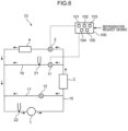
- the refrigeration apparatus may further include a bypass temperature detector that is disposed on the bypass flow path and is configured to detect a temperature of the refrigerant on a downstream side of the flow rate adjusting valve, and a suction temperature detector that is disposed on the main circuit and is configured to detect a temperature of the refrigerant suctioned into the compressor.
- the degree of superheat may be obtained from a temperature difference between a detection temperature of the suction temperature detector and a detection temperature of the bypass temperature detector.
- the detection temperature by the bypass temperature detector is a saturation temperature corresponding to the suction pressure.
- the degree of superheat of the refrigerant suctioned into the compressor is obtained from the temperature difference between the suction temperature detector that detects the temperature of the refrigerant suctioned into the compressor where the refrigerant from the bypass flow path and the refrigerant passing through the evaporator merge and the bypass temperature detector.
- the refrigeration apparatus may further include a hot gas bypass flow path that includes a hot gas valve, branches from a portion of the main circuit between the compressor and the condenser, and causes a refrigerant compressed by the compressor to be suctioned into the compressor without passing through the evaporator, and a hot gas control unit configured to open the hot gas valve so that a pressure of the refrigerant suctioned into the compressor does not become equal to or lower than a set pressure.
- a hot gas bypass flow path that includes a hot gas valve, branches from a portion of the main circuit between the compressor and the condenser, and causes a refrigerant compressed by the compressor to be suctioned into the compressor without passing through the evaporator
- a hot gas control unit configured to open the hot gas valve so that a pressure of the refrigerant suctioned into the compressor does not become equal to or lower than a set pressure.
- the hot gas flow rate adjusting valve is controlled by the hot gas control unit so that the suction pressure of the compressor does not become equal to or lower than the set pressure. That is, when the opening degree of the expansion valve decreases, the suction pressure of the compressor decreases accordingly, and thus, when the opening degree of the expansion valve is made very small to reduce the refrigeration capacity as much as possible, the suction pressure of the compressor may excessively decrease, and there is a possibility that stable operation cannot be performed. Accordingly, when the suction pressure is likely to become equal to or lower than the set pressure, the hot gas is suctioned into the compressor through the hot gas bypass flow path, whereby the suction pressure can be prevented from becoming equal to or lower than the set pressure. Therefore, it is possible to minimize the refrigeration capacity while ensuring the stable operation of the compressor.
- the hot gas control unit may be configured to control the hot gas valve according to the refrigeration request degree.
- the hot gas control unit can perform control to further open the hot gas valve. Therefore, when the refrigeration request degree is low, the refrigeration capacity can be reduced as much as possible. Furthermore, by suctioning the hot gas into the compressor through the hot gas bypass flow path, the suction pressure can be prevented from becoming equal to or lower than the set pressure. Therefore, it is possible to minimize the refrigeration capacity while ensuring the stable operation of the compressor.
- the environment forming apparatus includes an environment chamber and the refrigeration apparatus for cooling an inside of the environment chamber.
- the opening degree of the flow rate adjusting valve is controlled to be larger.
- the flow rate of the refrigerant flowing into the evaporator can be further reduced. Therefore, the refrigeration capacity exhibited by the evaporator can be reduced as compared with a case where the target value of the degree of superheat is fixed.
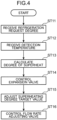
- a refrigeration method is a refrigeration method using a refrigeration apparatus, the refrigeration apparatus including a main circuit that includes a compressor, a condenser, an expansion valve, and an evaporator and is configured to circulate a refrigerant; a bypass flow path that includes a flow rate adjusting valve, branches from the main circuit between the condenser and the expansion valve, and causes a refrigerant liquefied in the condenser to be lowered in temperature by the flow rate adjusting valve and to be suctioned into the compressor without passing through the evaporator: and a reception unit, the refrigeration method including receiving a refrigeration request degree received by the reception unit, controlling the expansion valve according to the refrigeration request degree received by the reception unit, changing a target value of a degree of superheat with respect to a saturation temperature corresponding to a suction pressure of the compressor according to the refrigeration request degree or an opening degree of the expansion valve, and controlling the flow rate adjusting valve so that the degree of superheat becomes the changed target value.
- the refrigeration apparatus further includes a bypass temperature detector that is disposed in the bypass flow path and is configured to detect a temperature of the refrigerant on a downstream side of the flow rate adjusting valve, and a suction temperature detector that is disposed on the main circuit and is configured to detect a temperature of the refrigerant suctioned into the compressor, in the refrigeration method, the degree of superheat may be obtained from a temperature difference between a temperature detected by the suction temperature detector and a temperature detected by the bypass temperature detector.
- the refrigeration apparatus further includes a hot gas bypass flow path that includes a hot gas valve, branches from a portion of the main circuit between the compressor and the condenser, and is configured to cause a refrigerant compressed by the compressor to be suctioned into the compressor without passing through the evaporator, in the refrigeration method, the hot gas valve may be opened so that a pressure of the refrigerant suctioned into the compressor does not become equal to or lower than a set pressure.
- the refrigeration capacity of the evaporator can be adjusted while the compressor is stably driven by suction injection using the bypass flow path.
Landscapes
- Engineering & Computer Science (AREA)
- Mechanical Engineering (AREA)
- General Engineering & Computer Science (AREA)
- Physics & Mathematics (AREA)
- Thermal Sciences (AREA)
- Chemical & Material Sciences (AREA)
- Combustion & Propulsion (AREA)
- Life Sciences & Earth Sciences (AREA)
- Sustainable Development (AREA)
- Air Conditioning Control Device (AREA)
Applications Claiming Priority (1)
| Application Number | Priority Date | Filing Date | Title |
|---|---|---|---|
| JP2023146286A JP2025039296A (ja) | 2023-09-08 | 2023-09-08 | 冷凍装置、環境形成装置及び冷凍方法 |
Publications (1)
| Publication Number | Publication Date |
|---|---|
| EP4521039A1 true EP4521039A1 (de) | 2025-03-12 |
Family
ID=92708493
Family Applications (1)
| Application Number | Title | Priority Date | Filing Date |
|---|---|---|---|
| EP24198673.6A Pending EP4521039A1 (de) | 2023-09-08 | 2024-09-05 | Kühlvorrichtung, umgebungsformungsvorrichtung und kühlverfahren |
Country Status (3)
| Country | Link |
|---|---|
| EP (1) | EP4521039A1 (de) |
| JP (1) | JP2025039296A (de) |
| CN (1) | CN119594588A (de) |
Citations (4)
| Publication number | Priority date | Publication date | Assignee | Title |
|---|---|---|---|---|
| JPH064560U (ja) | 1992-06-23 | 1994-01-21 | 日東工業株式会社 | 空気調和機 |
| US20180149396A1 (en) * | 2015-06-24 | 2018-05-31 | Denso Corporation | Refrigeration cycle device |
| US20220357086A1 (en) * | 2020-02-20 | 2022-11-10 | Denso Corporation | Refrigeration cycle device |
| JP2023146286A (ja) | 2022-03-29 | 2023-10-12 | 東洋インキScホールディングス株式会社 | 農業資材用熱可塑性樹脂組成物及び農業資材 |
Family Cites Families (5)
| Publication number | Priority date | Publication date | Assignee | Title |
|---|---|---|---|---|
| JP3178192B2 (ja) * | 1993-10-22 | 2001-06-18 | 松下電器産業株式会社 | 冷凍サイクルの制御装置 |
| JP2008267653A (ja) * | 2007-04-18 | 2008-11-06 | Daikin Ind Ltd | 冷凍装置 |
| JP5109639B2 (ja) * | 2007-12-17 | 2012-12-26 | セイコーエプソン株式会社 | 電子部品の検査装置 |
| JP6062172B2 (ja) * | 2012-07-19 | 2017-01-18 | エスペック株式会社 | 環境試験装置 |
| KR101794413B1 (ko) * | 2015-09-30 | 2017-11-06 | 엘지전자 주식회사 | 공기 조화기 및 그 제어방법 |
-
2023
- 2023-09-08 JP JP2023146286A patent/JP2025039296A/ja active Pending
-
2024
- 2024-09-04 CN CN202411234524.7A patent/CN119594588A/zh active Pending
- 2024-09-05 EP EP24198673.6A patent/EP4521039A1/de active Pending
Patent Citations (4)
| Publication number | Priority date | Publication date | Assignee | Title |
|---|---|---|---|---|
| JPH064560U (ja) | 1992-06-23 | 1994-01-21 | 日東工業株式会社 | 空気調和機 |
| US20180149396A1 (en) * | 2015-06-24 | 2018-05-31 | Denso Corporation | Refrigeration cycle device |
| US20220357086A1 (en) * | 2020-02-20 | 2022-11-10 | Denso Corporation | Refrigeration cycle device |
| JP2023146286A (ja) | 2022-03-29 | 2023-10-12 | 東洋インキScホールディングス株式会社 | 農業資材用熱可塑性樹脂組成物及び農業資材 |
Also Published As
| Publication number | Publication date |
|---|---|
| JP2025039296A (ja) | 2025-03-21 |
| CN119594588A (zh) | 2025-03-11 |
Similar Documents
| Publication | Publication Date | Title |
|---|---|---|
| KR100755160B1 (ko) | 냉각 시스템의 제어 | |
| KR101106383B1 (ko) | 냉동장치 | |
| EP2270405B1 (de) | Kühlvorrichtung | |
| US20110162397A1 (en) | Flash tank economizer cycle control | |
| JP2009522533A (ja) | フラッシュタンクの冷媒制御 | |
| EP4517220A1 (de) | Kühlvorrichtung, umgebungserzeugungsvorrichtung und kühlverfahren | |
| EP4130615B1 (de) | Ausseneinheit und kühlzyklusvorrichtung | |
| JPH04240355A (ja) | 空気調和装置における電子膨脹弁の制御方法 | |
| US20180202689A1 (en) | Multi-stage compression refrigeration cycle device | |
| JP4767133B2 (ja) | 冷凍サイクル装置 | |
| JPH11281221A (ja) | オープンショーケースの冷却装置 | |
| US20240384908A1 (en) | Refrigerating device and environmental testing apparatus | |
| US20230131781A1 (en) | Refrigeration cycle apparatus | |
| JP4631721B2 (ja) | 蒸気圧縮式冷凍サイクル | |
| EP4553411A1 (de) | Kühlvorrichtung, umgebungsformungsvorrichtung und kühlverfahren | |
| JP2025039296A (ja) | 冷凍装置、環境形成装置及び冷凍方法 | |
| EP4556818A1 (de) | Kühlvorrichtung, umgebungsformungsvorrichtung und kühlverfahren | |
| KR101153420B1 (ko) | 에어컨의 제어 방법 | |
| JP6785381B2 (ja) | 冷凍サイクル装置 | |
| JP2003028516A (ja) | 冷凍サイクル制御装置 | |
| JP4690574B2 (ja) | 冷凍機における膨張弁の制御方法及び制御装置 | |
| KR102532023B1 (ko) | 초임계 냉각 시스템 및 그 제어방법 | |
| JPH0833242B2 (ja) | 冷凍装置 | |
| JPH05231723A (ja) | 冷凍装置 | |
| AU1550301A (en) | Refrigerating device |
Legal Events
| Date | Code | Title | Description |
|---|---|---|---|
| PUAI | Public reference made under article 153(3) epc to a published international application that has entered the european phase |
Free format text: ORIGINAL CODE: 0009012 |
|
| STAA | Information on the status of an ep patent application or granted ep patent |
Free format text: STATUS: THE APPLICATION HAS BEEN PUBLISHED |
|
| AK | Designated contracting states |
Kind code of ref document: A1 Designated state(s): AL AT BE BG CH CY CZ DE DK EE ES FI FR GB GR HR HU IE IS IT LI LT LU LV MC ME MK MT NL NO PL PT RO RS SE SI SK SM TR |
|
| STAA | Information on the status of an ep patent application or granted ep patent |
Free format text: STATUS: REQUEST FOR EXAMINATION WAS MADE |
|
| 17P | Request for examination filed |
Effective date: 20250826 |