EP4521072A1 - Transmetteur de pression active pour mesurer des courants de fluides gazeux et liquides et procédé correspondant - Google Patents
Transmetteur de pression active pour mesurer des courants de fluides gazeux et liquides et procédé correspondant Download PDFInfo
- Publication number
- EP4521072A1 EP4521072A1 EP23195480.1A EP23195480A EP4521072A1 EP 4521072 A1 EP4521072 A1 EP 4521072A1 EP 23195480 A EP23195480 A EP 23195480A EP 4521072 A1 EP4521072 A1 EP 4521072A1
- Authority
- EP
- European Patent Office
- Prior art keywords
- differential pressure
- section
- photocell
- pressure sensor
- tubular body
- Prior art date
- Legal status (The legal status is an assumption and is not a legal conclusion. Google has not performed a legal analysis and makes no representation as to the accuracy of the status listed.)
- Granted
Links
Images



Classifications
-
- G—PHYSICS
- G01—MEASURING; TESTING
- G01F—MEASURING VOLUME, VOLUME FLOW, MASS FLOW OR LIQUID LEVEL; METERING BY VOLUME
- G01F1/00—Measuring the volume flow or mass flow of fluid or fluent solid material wherein the fluid passes through a meter in a continuous flow
- G01F1/05—Measuring the volume flow or mass flow of fluid or fluent solid material wherein the fluid passes through a meter in a continuous flow by using mechanical effects
- G01F1/34—Measuring the volume flow or mass flow of fluid or fluent solid material wherein the fluid passes through a meter in a continuous flow by using mechanical effects by measuring pressure or differential pressure
- G01F1/36—Measuring the volume flow or mass flow of fluid or fluent solid material wherein the fluid passes through a meter in a continuous flow by using mechanical effects by measuring pressure or differential pressure the pressure or differential pressure being created by the use of flow constriction
- G01F1/40—Details of construction of the flow constriction devices
- G01F1/44—Venturi tubes
-
- G—PHYSICS
- G01—MEASURING; TESTING
- G01F—MEASURING VOLUME, VOLUME FLOW, MASS FLOW OR LIQUID LEVEL; METERING BY VOLUME
- G01F1/00—Measuring the volume flow or mass flow of fluid or fluent solid material wherein the fluid passes through a meter in a continuous flow
- G01F1/05—Measuring the volume flow or mass flow of fluid or fluent solid material wherein the fluid passes through a meter in a continuous flow by using mechanical effects
- G01F1/20—Measuring the volume flow or mass flow of fluid or fluent solid material wherein the fluid passes through a meter in a continuous flow by using mechanical effects by detection of dynamic effects of the flow
- G01F1/32—Measuring the volume flow or mass flow of fluid or fluent solid material wherein the fluid passes through a meter in a continuous flow by using mechanical effects by detection of dynamic effects of the flow using swirl flowmeters
- G01F1/325—Means for detecting quantities used as proxy variables for swirl
-
- G—PHYSICS
- G01—MEASURING; TESTING
- G01F—MEASURING VOLUME, VOLUME FLOW, MASS FLOW OR LIQUID LEVEL; METERING BY VOLUME
- G01F1/00—Measuring the volume flow or mass flow of fluid or fluent solid material wherein the fluid passes through a meter in a continuous flow
- G01F1/05—Measuring the volume flow or mass flow of fluid or fluent solid material wherein the fluid passes through a meter in a continuous flow by using mechanical effects
- G01F1/20—Measuring the volume flow or mass flow of fluid or fluent solid material wherein the fluid passes through a meter in a continuous flow by using mechanical effects by detection of dynamic effects of the flow
- G01F1/32—Measuring the volume flow or mass flow of fluid or fluent solid material wherein the fluid passes through a meter in a continuous flow by using mechanical effects by detection of dynamic effects of the flow using swirl flowmeters
- G01F1/325—Means for detecting quantities used as proxy variables for swirl
- G01F1/3259—Means for detecting quantities used as proxy variables for swirl for detecting fluid pressure oscillations
-
- G—PHYSICS
- G01—MEASURING; TESTING
- G01F—MEASURING VOLUME, VOLUME FLOW, MASS FLOW OR LIQUID LEVEL; METERING BY VOLUME
- G01F1/00—Measuring the volume flow or mass flow of fluid or fluent solid material wherein the fluid passes through a meter in a continuous flow
- G01F1/05—Measuring the volume flow or mass flow of fluid or fluent solid material wherein the fluid passes through a meter in a continuous flow by using mechanical effects
- G01F1/20—Measuring the volume flow or mass flow of fluid or fluent solid material wherein the fluid passes through a meter in a continuous flow by using mechanical effects by detection of dynamic effects of the flow
- G01F1/32—Measuring the volume flow or mass flow of fluid or fluent solid material wherein the fluid passes through a meter in a continuous flow by using mechanical effects by detection of dynamic effects of the flow using swirl flowmeters
- G01F1/325—Means for detecting quantities used as proxy variables for swirl
- G01F1/3282—Means for detecting quantities used as proxy variables for swirl for detecting variations in infrasonic, sonic or ultrasonic waves, due to modulation by passing through the swirling fluid
-
- G—PHYSICS
- G01—MEASURING; TESTING
- G01F—MEASURING VOLUME, VOLUME FLOW, MASS FLOW OR LIQUID LEVEL; METERING BY VOLUME
- G01F1/00—Measuring the volume flow or mass flow of fluid or fluent solid material wherein the fluid passes through a meter in a continuous flow
- G01F1/05—Measuring the volume flow or mass flow of fluid or fluent solid material wherein the fluid passes through a meter in a continuous flow by using mechanical effects
- G01F1/34—Measuring the volume flow or mass flow of fluid or fluent solid material wherein the fluid passes through a meter in a continuous flow by using mechanical effects by measuring pressure or differential pressure
- G01F1/36—Measuring the volume flow or mass flow of fluid or fluent solid material wherein the fluid passes through a meter in a continuous flow by using mechanical effects by measuring pressure or differential pressure the pressure or differential pressure being created by the use of flow constriction
- G01F1/363—Measuring the volume flow or mass flow of fluid or fluent solid material wherein the fluid passes through a meter in a continuous flow by using mechanical effects by measuring pressure or differential pressure the pressure or differential pressure being created by the use of flow constriction with electrical or electro-mechanical indication
-
- G—PHYSICS
- G01—MEASURING; TESTING
- G01F—MEASURING VOLUME, VOLUME FLOW, MASS FLOW OR LIQUID LEVEL; METERING BY VOLUME
- G01F1/00—Measuring the volume flow or mass flow of fluid or fluent solid material wherein the fluid passes through a meter in a continuous flow
- G01F1/66—Measuring the volume flow or mass flow of fluid or fluent solid material wherein the fluid passes through a meter in a continuous flow by measuring frequency, phase shift or propagation time of electromagnetic or other waves, e.g. using ultrasonic flowmeters
-
- G—PHYSICS
- G01—MEASURING; TESTING
- G01F—MEASURING VOLUME, VOLUME FLOW, MASS FLOW OR LIQUID LEVEL; METERING BY VOLUME
- G01F1/00—Measuring the volume flow or mass flow of fluid or fluent solid material wherein the fluid passes through a meter in a continuous flow
- G01F1/66—Measuring the volume flow or mass flow of fluid or fluent solid material wherein the fluid passes through a meter in a continuous flow by measuring frequency, phase shift or propagation time of electromagnetic or other waves, e.g. using ultrasonic flowmeters
- G01F1/661—Measuring the volume flow or mass flow of fluid or fluent solid material wherein the fluid passes through a meter in a continuous flow by measuring frequency, phase shift or propagation time of electromagnetic or other waves, e.g. using ultrasonic flowmeters using light
-
- G—PHYSICS
- G01—MEASURING; TESTING
- G01F—MEASURING VOLUME, VOLUME FLOW, MASS FLOW OR LIQUID LEVEL; METERING BY VOLUME
- G01F1/00—Measuring the volume flow or mass flow of fluid or fluent solid material wherein the fluid passes through a meter in a continuous flow
- G01F1/66—Measuring the volume flow or mass flow of fluid or fluent solid material wherein the fluid passes through a meter in a continuous flow by measuring frequency, phase shift or propagation time of electromagnetic or other waves, e.g. using ultrasonic flowmeters
- G01F1/662—Constructional details
-
- G—PHYSICS
- G01—MEASURING; TESTING
- G01F—MEASURING VOLUME, VOLUME FLOW, MASS FLOW OR LIQUID LEVEL; METERING BY VOLUME
- G01F1/00—Measuring the volume flow or mass flow of fluid or fluent solid material wherein the fluid passes through a meter in a continuous flow
- G01F1/66—Measuring the volume flow or mass flow of fluid or fluent solid material wherein the fluid passes through a meter in a continuous flow by measuring frequency, phase shift or propagation time of electromagnetic or other waves, e.g. using ultrasonic flowmeters
- G01F1/667—Arrangements of transducers for ultrasonic flowmeters; Circuits for operating ultrasonic flowmeters
- G01F1/668—Compensating or correcting for variations in velocity of sound
-
- G—PHYSICS
- G01—MEASURING; TESTING
- G01F—MEASURING VOLUME, VOLUME FLOW, MASS FLOW OR LIQUID LEVEL; METERING BY VOLUME
- G01F1/00—Measuring the volume flow or mass flow of fluid or fluent solid material wherein the fluid passes through a meter in a continuous flow
- G01F1/74—Devices for measuring flow of a fluid or flow of a fluent solid material in suspension in another fluid
-
- G—PHYSICS
- G01—MEASURING; TESTING
- G01F—MEASURING VOLUME, VOLUME FLOW, MASS FLOW OR LIQUID LEVEL; METERING BY VOLUME
- G01F15/00—Details of, or accessories for, apparatus of groups G01F1/00 - G01F13/00 insofar as such details or appliances are not adapted to particular types of such apparatus
- G01F15/02—Compensating or correcting for variations in pressure, density or temperature
- G01F15/022—Compensating or correcting for variations in pressure, density or temperature using electrical means
- G01F15/024—Compensating or correcting for variations in pressure, density or temperature using electrical means involving digital counting
-
- G—PHYSICS
- G01—MEASURING; TESTING
- G01N—INVESTIGATING OR ANALYSING MATERIALS BY DETERMINING THEIR CHEMICAL OR PHYSICAL PROPERTIES
- G01N21/00—Investigating or analysing materials by the use of optical means, i.e. using sub-millimetre waves, infrared, visible or ultraviolet light
- G01N21/17—Systems in which incident light is modified in accordance with the properties of the material investigated
- G01N21/55—Specular reflectivity
-
- G—PHYSICS
- G01—MEASURING; TESTING
- G01N—INVESTIGATING OR ANALYSING MATERIALS BY DETERMINING THEIR CHEMICAL OR PHYSICAL PROPERTIES
- G01N21/00—Investigating or analysing materials by the use of optical means, i.e. using sub-millimetre waves, infrared, visible or ultraviolet light
- G01N21/84—Systems specially adapted for particular applications
- G01N21/88—Investigating the presence of flaws or contamination
-
- G—PHYSICS
- G01—MEASURING; TESTING
- G01N—INVESTIGATING OR ANALYSING MATERIALS BY DETERMINING THEIR CHEMICAL OR PHYSICAL PROPERTIES
- G01N29/00—Investigating or analysing materials by the use of ultrasonic, sonic or infrasonic waves; Visualisation of the interior of objects by transmitting ultrasonic or sonic waves through the object
- G01N29/02—Analysing fluids
- G01N29/024—Analysing fluids by measuring propagation velocity or propagation time of acoustic waves
-
- G—PHYSICS
- G01—MEASURING; TESTING
- G01N—INVESTIGATING OR ANALYSING MATERIALS BY DETERMINING THEIR CHEMICAL OR PHYSICAL PROPERTIES
- G01N29/00—Investigating or analysing materials by the use of ultrasonic, sonic or infrasonic waves; Visualisation of the interior of objects by transmitting ultrasonic or sonic waves through the object
- G01N29/22—Details, e.g. general constructional or apparatus details
- G01N29/222—Constructional or flow details for analysing fluids
-
- G—PHYSICS
- G01—MEASURING; TESTING
- G01N—INVESTIGATING OR ANALYSING MATERIALS BY DETERMINING THEIR CHEMICAL OR PHYSICAL PROPERTIES
- G01N2291/00—Indexing codes associated with group G01N29/00
- G01N2291/02—Indexing codes associated with the analysed material
- G01N2291/028—Material parameters
- G01N2291/02818—Density, viscosity
Definitions
- the invention relates to a differential pressure sensor for measuring flows of gaseous and liquid fluids and a corresponding method for determining the measuring accuracy of a differential pressure sensor.
- the invention is based on a differential pressure sensor for measuring flows of gaseous and liquid fluids, comprising a tubular body arranged between a first and a second connection element, wherein a fluid flows into the tubular body through the first connection element and out through the second connection element, wherein the tubular body has a first section with a first diameter and, arranged downstream thereof, a second section with a second diameter which is smaller than the first diameter, wherein a first pressure measuring device is arranged in the first section and a second pressure measuring device is arranged in the second section, wherein a differential pressure between the first and second sections can be determined by means of the pressure measuring devices.
- a differential pressure sensor is already known from the publication DE 10 2017 001 049 A1 .
- Flowmeters for gaseous and liquid fluids that rely on the difference in differential pressure have been in use for decades. They use a pressure difference across cross-sectional constrictions in pipes or containers to determine the flow.
- Cross-sectional constrictions can be created using nozzles, orifices, Venturi throttle devices, and bluff bodies such as cones, baffles, or wedges. Due to the constriction, the velocity of the measuring medium increases while the pressure drops simultaneously between two defined points where pressure sensors are positioned. The pressure difference is proportional to the square of the flow velocity.
- evaluation electronics the volume flow per unit of time can be determined, and with knowledge of the density of the flowing medium, the mass flow can be determined.
- the focus of all measurement processes is on the measurement errors of the measured results. They consist of systematic and random measurement errors. Systematic measurement errors can be detected on test benches. In such a case, the measured value is corrected for the known systematic measurement errors when calculating the measured value. If necessary, gas meters are readjusted on test benches and their remaining measurement error is verified with further test bench measurements (part of calibration or verification). In commercial and official transactions, measurement results must lie within permissible measurement errors according to the European Measuring Instruments Directive. These limits, also known as error limits, are specified in the Measuring Instruments Directive and in its national implementation – in Germany, in the Measuring and Verification Ordinance (MessEV). These are device-specific parameters that must be verifiably adhered to during operation.
- the measurement result is expressed as a measured value and an associated measurement uncertainty.
- This uncertainty can be positive or negative.
- the measurement uncertainty represents the random influences on the measurement process, e.g., randomly occurring disturbances such as particles in the fluid flow, Pressure surges, temperature fluctuations, and fluctuations in the medium's composition manifest as temporary measurement errors. These are not device-specific variables and are therefore assigned to the measured value in the form of an uncertainty value. As the measurement uncertainty increases, repeated measurements become less precise. As a guideline, the International Organization of Legal Metrology (OIML) specifies that the measurement uncertainty may not exceed one-third of the measuring instrument's error limit. Measurement uncertainties are documented in the calibration or verification certificate.
- media-dependent minimum speeds are specified to reliably prevent the loss of water from moist media. Since process-related downtime cannot be ruled out, even with low moisture content, water droplets in the pipeline, connected systems, or measuring devices, and thus corrosion, can be expected. Abrasion, erosion, or corrosion have a significant adverse effect on measurement accuracy; the measurement stability required by the European Measuring Instruments Directive (MID) and the German Measuring Instruments Ordinance (MessEV) may no longer be met.
- MID European Measuring Instruments Directive
- MessEV German Measuring Instruments Ordinance
- a source for emitting electromagnetic radiation for example bundled light, a reflecting surface and at least one photocell are arranged in the tubular body, which are aligned with one another in such a way that the radiation emitted by the source falls on the reflecting surface and is reflected by it in a directed or diffuse manner onto the photocell, wherein the differential pressure sensor further comprises an evaluation unit by means of which a decrease and/or increase in the radiation intensity detected by the photocell can be determined.
- the differential pressure sensor can receive information from a sensor system in the measuring device that detects wear caused by abrasion, erosion, and corrosion.
- the influence of wear on the measured value generation can be determined in advance on certified test benches or with test equipment in recognized testing laboratories using test equipment or material samples, depending on the medium, its properties, and the operating conditions (if unknown), and stored in operating manuals or electronically in the device itself.
- the measuring device can itself use the stored or saved information to decide to what extent the measured value should be corrected during measurement generation or, if wear is still acceptable, to ignore it. Complex intermediate tests, as are common with differential pressure sensors, can thus be reduced or even completely avoided.
- the invention avoids questions about the influence of wear and increases the confidence of the trading partners involved in the measurement result. This applies particularly to commercial or official transactions.
- the correction device integrated into the measuring device is considerably more cost-effective than removing the measuring device, operating another measuring device as a substitute and/or (re-)calibrating it on a certified and recognized test bench for the corresponding medium.
- the invention utilizes the different behavior of directed and diffuse reflection.
- An electromagnetic wave transparent to the process fluid such as a light signal, is directed at the point in the differential pressure sensor where, for example, the greatest abrasion, erosion, or corrosion is expected. This is usually the point with the highest flow velocity at the end of the confuser section.
- This location is designed to be metallically reflective.
- the reflection of the wave or light beam from the reflective inner surface can be described by the law of reflection (angle of incidence equals angle of reflection). If the reflective surface becomes rougher due to abrasion, erosion, or corrosion, the directed reflection transitions into diffuse reflection.
- the reflective surface acquires many scattering centers, which, in sum, result in the main backscattering occurring independently of the law of reflection. It then occurs perpendicular to the material. Diffuse scattering follows Lambert's law.
- the electromagnetic beam in particular the light beam
- the first photocell which is arranged diagonally opposite the reflective surface.
- the second photocell which is arranged perpendicularly opposite the reflective surface, receives almost none of the light wave scattered by the reflective surface.
- the reflective surface becomes rougher, and the directed reflection increasingly turns into diffuse reflection.
- the ratio of the light output of the photocells can consequently be correlated with the laboratory or test bench results for the wear of the reflective metallic surface. This allows the differential pressure sensor to determine a value to determine permissible or impermissible wear values or, with stored test bench information on the relationship between wear progression and measurement error or the extent of measurement accuracy, to automatically correct it.
- the reflecting surface can be a mirror. It can also be a ground metallic surface inside the tubular body. Any curvature of the position due to the design is irrelevant for the reflection. Directional reflections also occur on concave mirrors such as shaving mirrors or astronomical reflecting telescopes, or on convex exterior car mirrors, and therefore also on a reflective metallic surface on the inner wall of the differential pressure sensor.
- the resulting systematic measurement error or, more correctly, the systematic measurement deviation is determined and corrected.
- Systematic measurement deviations can be evaluated and quantified on test benches. It can be provided that corresponding values are recorded experimentally before field use and stored, for example, in a table in the evaluation unit of the differential pressure sensor. The table can then be used to correct the measurement result during operation. For this purpose, a threshold value of a sensor in the differential pressure sensor can be monitored during operation. When the threshold value(s) are reached, the subsequent measured values are automatically corrected. As long as the threshold value is not exceeded, additional measurement deviations are accepted and neglected.
- At least one photocell is arranged symmetrically to the source with respect to the reflecting surface, such that the directed beam reflected by the reflecting surface strikes the photocell, wherein the evaluation unit detects when the radiation intensity detected by the photocell falls below a predetermined threshold.
- the decrease in the radiation intensity of the directed reflection detected by the diagonally opposite photocell is accompanied by increasing wear of the reflecting surface, and the proportion of diffuse reflection increases.
- the angle of incidence or the angle of reflection of the light beam can preferably be selected so that as little scattered light from the directed reflection as possible enters the second photocell. This means choosing the angles as large as possible. However, the angles are structurally limited by the maximum length of the outflow area of the tubular body and are then calculated purely mathematically from the cotangent of the ratio of the length of the outflow area to the diameter of the outflow area.
- At least one photocell is arranged perpendicularly opposite the reflecting surface in such a way that the main backscatter of the diffuse reflection reflected by the reflecting surface strikes the photocell, wherein the evaluation unit detects when a predetermined threshold value of the radiation intensity detected by the photocell is exceeded.
- the increase in the radiation intensity of the diffuse reflection detected by the photocell perpendicularly opposite the reflecting surface is accompanied by increasing wear of the reflecting surface, and the proportion of directed reflection decreases.
- the reflective surface is arranged between the first and second pressure measuring devices. Furthermore, the reflective surface can be positioned at a gravitational lowest point of the pipe body relative to the pipe circumference. This can be useful if the influence of contamination, e.g., oil on the inner wall of the measuring device, is also to be detected. In principle, however, the reflective surface can also be mounted at other positions. The entire sensor device would then be rotated and positioned rotationally symmetrically, figuratively speaking.
- the reflecting surface can be arranged in the pipe body, for example at the point with the highest flow velocity with respect to the flow direction, for example in the second section with a reduced diameter compared to the first section.
- the source of electromagnetic radiation can be arranged upstream of the first pressure measuring device.
- the photocell arranged diagonally opposite the reflecting surface, can be arranged downstream of the second pressure measuring device.
- the photocell can also be positioned upstream or downstream of the pressure sensor.
- the reflective surface can be provided with a coating designed to determine the influence of a specific accompanying substance, such as moisture, on measurement accuracy.
- a specific accompanying substance such as moisture
- Advantages include the ability to specifically adapt abrasion, erosion, or corrosion to the flowing medium or accompanying substances.
- precipitation of moisture could also cloud the coating, allowing the transition from directed to diffuse reflection to occur more precisely and/or more quickly.
- the invention further relates to a differential pressure transducer for measuring flows of gaseous and liquid fluids, comprising a tubular body which is arranged between a first and a second connection element, wherein it is provided that a fluid flows into the tubular body through the first connection element and flows out through the second connection element, wherein the tubular body has a first section with a first diameter and, arranged downstream thereof, a second section with a second diameter which is smaller than the first diameter, wherein a first pressure measuring device is arranged in the first section and a second pressure measuring device is arranged in the second section, wherein a differential pressure between the first and second sections can be determined by means of the pressure measuring devices, wherein a plurality of pressure sensors for detecting the local fluid pressure are arranged in the inflow section or in the compensation pipe and are distributed radially over the pipe circumference, said pressure sensors being connected to the evaluation unit, wherein the evaluation unit is configured to detect the swirl of the inflowing fluid or to correct the measurement result accordingly based on the pressure differences determined by means of
- an inflow section is arranged upstream of the first section, over the circumference of which the plurality of pressure sensors for detecting the local fluid pressure are arranged radially distributed, which are connected to the evaluation unit, wherein the evaluation unit is set up to to detect the swirl of the inflowing fluid by means of the pressure differences determined over the circumference of the inflow section by means of the plurality of pressure sensors.
- Separating the pressure sensors for detecting the differential pressure and the turbulence (swirl) that adversely affects the measurement results is advantageous, since the differential pressure and the pressure changes caused by swirl or turbulence can occur in different value ranges or scales. Separating the pressure sensors allows for both technical and economic optimization of the pressure sensors.
- the pressure sensors are used to improve measurement accuracy by detecting swirl in the process fluid, which can be caused by inlet disturbances (e.g., pipe bends or fittings in the connected pipes upstream of the measuring device).
- inlet disturbances e.g., pipe bends or fittings in the connected pipes upstream of the measuring device.
- the arrangement of two or more measuring transducers, such as pressure sensors, distributed around the circumference of the measuring tube results in dynamic measurement data acquisition across multiple paths and increases the accuracy of determining flow disturbances caused by vortex and swirl.
- the automatic zero point correction process can also be optimized and verified.
- State-of-the-art technology involves zeroing the differential pressure transmitter while it is installed by isolating it from the process and opening a compensation line via a manual valve block. With two or more sensors, this correction can be performed while the medium is at rest. One sensor monitors whether the process fluid is moving while the other sensor is performing its zero point correction. Manual intervention is therefore no longer necessary.
- the invention further relates to a differential pressure sensor for measuring flows of gaseous and liquid fluids, comprising a tubular body which is arranged between a first and a second connection element, wherein it is provided that a fluid flows into the tubular body through the first connection element and out through the second connection element, wherein the tubular body has a first section with a first diameter and, arranged downstream thereof, a second section with a second diameter which is smaller than the first diameter, wherein a first pressure measuring device is arranged in the first section and a second pressure measuring device is arranged in the second section, wherein a differential pressure between the first and second sections can be determined by means of the pressure measuring devices, wherein a measuring device is arranged in an inflow section between the first connection element and the first section or in an outflow section between the second section and the second connection element of the differential pressure sensor for determining density fluctuations of the process fluid, which comprises an ultrasonic transmitter and an ultrasonic receiver which are aligned with one another in such a way that an ultrasonic pulse emitted
- the density of the gas fluctuates, which in turn significantly influences the measurement result of a differential pressure measuring device.
- This influence is not systematic but random, as it depends on the amount of hydrogen fed in and on the wind and solar energy. Such influences are random disturbances that significantly increase the measurement uncertainty of the differential pressure measuring device and impair confidence in the measurement result.
- network operators use quality measuring devices approved by calibration law, such as process gas chromatographs, or calculate the quality using complex gas quality tracking systems that must be approved by calibration law.
- the increase or drift of the measurement uncertainty due to density fluctuations is registered by means of an additional sensor device and taken into account in the measurement value generation according to the calculation specification according to ISO 5167-1 to 6.
- the measurement value generation can be suppressed and this suppression can be displayed as a fault on the counter/index or made available at electronic interfaces.
- Differential pressure sensors measure the flow of fluids whose composition can change.
- complex media such as natural gas
- a shift in the material proportions up to the percentage range is common. This occurs, for example, in complex network structures with multi-point feeds.
- a typical example is a municipal distribution network with natural gas as its main component, into which biogas and/or hydrogen is fed at various points. Due to the process, however, it is almost impossible for the measuring sections installed in the network to be confronted with completely different media one after the other – e.g., gas followed by liquids. This means that the physicochemical parameters of the material flow can change or fluctuate continuously, but they do not jump by orders of magnitude to completely different values.
- one object of the invention is to improve a differential pressure sensor in such a way that it can take into account density fluctuations of the process fluid when determining the flow rate.
- Density fluctuations correspond directly to fluctuations in the medium's sound velocity.
- the means to detect such fluctuations are time-of-flight measurements of acoustic waves, preferably ultrasonic signals, through the medium.
- a pair of ultrasonic sensors is positioned in the compensation tube so that the emitted ultrasonic pulse travels from the first through the medium to the second receiving ultrasonic sensor.
- the required transmitter or transducer can be integrated into the electronics of the differential pressure sensor.
- an ultrasonic transmitter and receiver are located in the compensation pipe or in the downstream area.
- the invention will be further discussed below with reference to the positioning of the sensor pair in the compensation pipe.
- the sensors can be positioned instead of one sensor at the lowest point of the pipe preferably positioned in the 3 or 9 o'clock position of the compensation tube. Furthermore, the sensors can be arranged slightly recessed in the wall of the compensation tube in such a way that a sufficiently strong ultrasonic pulse can be emitted into the compensation tube and at the same time abrasion or erosion of the sensor by the flow is minimized.
- the pulse from the transmitting sensor can be transmitted directly to the receiver, e.g. from the 3 to the 9 o'clock position. Instead of direct radiation of the acoustic signal from the transmitter to the receiver, the acoustic signal can in principle also be transmitted from the transmitter to the receiver by reflection off the inner wall of the compensation tube.
- the propagation time is the time of receipt of the acoustic signal minus the time of the transmitted signal.
- the change in transit time is a strong indicator of density fluctuations in the medium, provided that it can be assumed that the medium does not fundamentally change, which is the case with the piped supply of gases to the general public, as explained above.
- the increase in measurement uncertainty can be calculated from the frequency of the density fluctuations and, on this basis, the measurement result (measured value and measurement uncertainty) can be specified or the drift in the measurement uncertainty can be compensated electronically in the differential pressure sensor.
- the test bench results can be stored in the evaluation unit and used to compensate for the measurement uncertainty due to changes in the properties, depending on the density fluctuation measured using the invention.
- Such a combination of "measured instead of theoretical (calculated) testing” with the inventive device for the purpose of compensation can be considered a quality feature of the respective primary pressure sensor placed on the market. It can be performed as part of the generally required calibration or verification and significantly increases the acceptance of the inventive compensation of increased or drifting measurement uncertainties in the primary pressure sensor.
- the ultrasonic transmitter and the ultrasonic receiver are arranged opposite each other and, with respect to the pipe circumference, are each located outside the gravitational lowest point of the pipe body. Furthermore, it can be provided that the ultrasonic transmitter and the ultrasonic receiver are arranged one behind the other in the direction of flow. are arranged in the inflow section or in the outflow section and are aligned with each other in such a way that an ultrasonic pulse emitted by the ultrasonic transmitter is reflected back by the opposite inner pipe wall and from there to the ultrasonic receiver.
- the ultrasonic transmitter and the ultrasonic receiver can be recessed into the wall of the pipe body.
- the ultrasonic transmitter and the ultrasonic receiver can be arranged behind the inner pipe wall, so that the ultrasonic transmitter and the ultrasonic receiver are shielded from the process fluid and thus from the wear-promoting elements contained therein.
- the invention further relates to a method for determining the measurement accuracy of a differential pressure sensor, in particular according to one of the preceding claims, comprising the steps of: passing a process fluid through the differential pressure sensor; determining a first pressure in a first section of a tubular body of the differential pressure sensor and determining a second pressure in a second section of the tubular body, wherein the inner diameter of the tubular body is greater in the first section than in the second section; determining the pressure difference between the first and second pressures and determining a flow rate of the process fluid passed through; emitting an electromagnetic wave from a source arranged on or in an inner wall of the tubular body onto a reflecting surface arranged on an inner wall section of the tubular body opposite the source, wherein the electromagnetic wave does not impinge perpendicularly on the reflecting surface; directed reflection of the electromagnetic wave from the reflecting surface onto a photocell located diagonally opposite the reflecting surface and/or diffuse reflection onto a photocell located perpendicularly opposite the reflecting surface; Determining a decrease in the radiation intensity
- the measured value can be electronically corrected by the systematic measurement deviation caused by the wear (deviation compensation).
- the predetermined threshold value is displayed as a warning on the index (counter) of the differential pressure sensor or that it is signaled to the automation system. Furthermore, it can be provided that an alarm is communicated to the operator when a further threshold value is reached.
- the tubular body can initially have an inflow section with a first flow cross-section, viewed in the direction of flow of the fluid.
- the tubular body can then have a diffuser section with a flow cross-section that continuously increases up to a second flow cross-section. This can be followed by a confuser section with a flow cross-section that continuously decreases down to the first flow cross-section.
- An outflow section with the first flow cross-section can then be arranged.
- the first pressure measuring device can be arranged in the inflow section or in the outflow section.
- the second pressure measuring device can be arranged in the region of the second flow cross-section. It can be provided that a compensating tube is arranged between the first connection element and the inflow section, and that a ratio between a compensating tube length of the compensating tube and an internal tube dimension of the compensating tube is at least 2.5.
- At least one third pressure measuring device is arranged in the inflow section or in the outflow section, so that the inflow section and the outflow section have either the at least one second or the at least one third pressure measuring device.
- a quotient of a second internal dimension of the pipe body to a first internal dimension of the inflow section is at least 1.2 and at most 2.5, but ideally 1.5.
- a quotient of a length of the diffuser section to a length of the confuser section, seen in the flow direction is at least 1 and at most 5, preferably 3.7.
- the quotient of the second internal dimension of the tube body to the length of the diffuser section may be at least 0.3 and at most 0.5.
- a measuring section can be interposed between the diffuser section and the confuser section, which measuring section has the second internal dimension and a measuring section length whose maximum length corresponds to the value of half the first internal dimension.
- At least one of the pressure measuring devices is designed as a coupling recess in such a way that it is suitable for connecting a coupling element or for introducing sensors for visual inspection, for geometric measurement or for calibrating the metrologically relevant area of the pipe body interior.
- the at least one coupling recess can cooperate with a coupling element connected to the tubular body, which has a first and/or a second connection recess for a pressure measuring sensor or a differential pressure line of a pressure measuring device or is suitable for connecting or introducing sensors.
- connection recess can be closed or glued or welded by an externally threaded cap, an internally threaded plug, a flange cover, a clamp cover or another closure element.
- the connecting element is connected to a compensating device with which the free volume in the differential pressure line can be changed.
- the connecting element can be connected to a cleaning device with which the pressure relief recess connected to the connecting element can be cleaned as required.
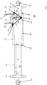
- Fig. 1 shows an embodiment of the differential pressure transducer 10 according to the invention with a circular flow cross-section in a sectional view through its longitudinal extent. Therefore, in the following, the internal dimensions or internal pipe dimensions are always referred to as diameters.
- the section is taken through a central axis 12 of the first differential pressure transducer 10, and a flow direction of a fluid through the first differential pressure transducer 10 is indicated by an inflow arrow 14 and an outflow arrow 16.
- a fluid initially flows through a first connection element 18, which has a pipe-shaped inner region with a constant inner diameter 19 and, in the example shown, is designed as a screw flange.
- connection options for example a welded flange or adhesive connection element.
- the first connection element 18 is connected downstream, for example welded, to a first end of a compensating pipe 20, which has a constant pipe inner diameter 21 and a compensating pipe length 23.
- a second end of the compensating tube 20 is connected to one end of the tubular body 22, the other end of which is connected to a second connecting element 24.
- the second connecting element 24 is also designed as a screw flange, but can also be designed as a different connecting piece, like the first connecting element 18.
- the first connecting element 18, the compensating tube 20, the tubular body 22, and the second connecting element 24 are made of steel, preferably the same material as the pipeline into which the differential pressure sensor 10 is installed.
- the choice of material can also depend on the fluid intended to flow through the differential pressure sensor, for example, whether it is corrosive or contaminated with contaminants that have an abrasive effect. In this case, a material with particularly low wear must be selected. In this way, the internal geometry of the differential pressure sensor 10 undergoes only minor changes during its operating period.
- the tubular body 22 can be divided into various sections along its longitudinal extent.
- the inflow section 26 Corresponding to the first inner diameter 28, the inflow section 26 has a first flow cross-section.
- a diffuser section 30 Downstream of the inflow section 26 is a diffuser section 30, the circular inner diameter of which increases continuously in the flow direction until a second inner diameter 32 is reached.
- the flow cross-section for the fluid increases continuously from the first flow cross-section to a second flow cross-section, which is reached at the second inner diameter 32.
- the second inner diameter 32 is also the maximum inner diameter of the tubular body. Accordingly, the velocity of the medium is slowed down in the flow direction and its static pressure component is increased at this point compared to the area of the first inner diameter 28.
- the tubular body 22 Downstream of the diffuser section 28, the tubular body 22 has a confuser section 34, also called a nozzle section, whose inner diameter continuously decreases from the second inner diameter 32 back to the first inner diameter 28. Accordingly, in the outflow section 34 following the confuser section with the first inner diameter 28, the first flow cross section is again set at the same flow velocities as in the inflow section 26.
- a confuser section 34 also called a nozzle section
- the ratio between the second inner diameter 32 and the first inner diameter 28 is approximately 1.4, which is within a typical range of 1.2 to 2.5. However, depending on the fluid, flow velocity, pipe diameter, operating pressure, and other boundary conditions, this ratio can vary within the specified range.
- the ratio of the second inner diameter 32 and the length of the diffuser section 30 in its longitudinal extent is between 0.3 and 0.5.
- the ratio between the length of the diffuser section 30 and the confuser section 34 also influences the pressure measurement. It has proven advantageous if this ratio is between 0.3 and 0.5.
- DN 100 inlet flange 19 results in a nominal diameter of 100 mm at the inlet of diffuser 28.
- the nominal diameter can be between 120 and 250 mm.
- the ratio of the inner diameter at position 32 to the length of the diffuser section 30 should be between 0.3 and 0.5. Therefore, the optimal length of the diffuser 30 can vary between 280 and 467 mm.
- the ratio of the length of the confuser section 34 to the length of the diffuser section 30 should also preferably be between 0.3 and 0.5.
- the confuser for example, with a DN 100 inlet flange, should preferably be dimensioned with a length between 84 and 234 mm (rounded).
- a second coupling recess 44 is shown as a bore through the tubular body 22.
- a second coupling element 40 Attached to the outside of the second coupling recess 38 is a second coupling element 40, the through-bore of which corresponds, on the one hand, to the second coupling recess 38 and, on the other hand, has a connecting element connected to a first impulse line 42 or differential pressure line of a pressure measuring device or flow measuring computer (not shown in the figure). This enables the pressure measurement to be carried out through the coupling recess 38 directly on the inner surface of the tubular body 22 in the outflow section 36.
- a variety of designs are possible as pressure sensors for the pressure measurement, for example a hydraulic U-tube manometer, a single pressure sensor, a differential pressure sensor, or a combined differential pressure sensor with integrated separate pressure measurement.
- a pressure measuring point in the region of the first inner diameter 32 has a comparable structure. Namely, a first coupling recess 44 is arranged there in the tubular body 22, above which a first coupling element 46 is mounted, the through-bore of which in turn corresponds on the one hand to the first coupling recess 44, and on the other hand has a further connection element to which a second impulse line 48 is connected.
- a direct pressure measurement of the pressure in the region of the first inner diameter 32 is carried out without the interposition of an otherwise necessary pressure equalization element, such as a pressure equalization annular space.
- pressure measurement at only one point on the circumference of the tubular body 22 in the region of the first inner diameter 32 or in the outflow section 36 is entirely sufficient for measuring or calculating pressures or pressure differences.
- the minimum length of the compensating tube 20 for a given diameter should have a ratio of at least 2.5 so that advantageous flow conditions for pressure measurement are established in the differential pressure sensor. This takes into account that the length of the first connection element 18 and the length of the first inflow section 26 are added to the length of the compensating tube 20 for their effect on the flow conditions in the differential pressure sensor.
- the ratio of the total length to the tube diameter 21 will therefore be at least 3. Only downstream of the inflow section 26 does the deceleration of the fluid velocity begin due to the increase in the inner diameter in the diffuser section 30.
- the invention utilizes the different behavior of directed and diffuse reflection.
- the resulting systematic measurement error or more correctly, the systematic measurement deviation, can be determined and corrected.
- Systematic measurement deviations can be evaluated (quantified) on test benches. This can also be recorded experimentally before field use and, for example, stored in a table in the evaluation electronics of the differential pressure sensor 10. The table is then used to correct the measurement result during operation.
- a threshold value of a sensor in the differential pressure sensor 10 is monitored during operation. When the threshold value(s) are reached, the following measured values are automatically corrected. Below the threshold value, additional measurement deviations are accepted and neglected.
- An electromagnetic wave transparent to the medium is directed at a point in the differential pressure transducer 10 where the greatest erosion or corrosion is expected. Typically, this is the point with the highest flow velocity at the end of the confuser section 34.
- This point is designed to be metallically reflective, or a reflective surface 80 is arranged at this point.
- the reflection of the wave or light beam from the reflective inner surface can be described by the law of reflection (angle of incidence equals angle of reflection). If the reflective surface 80 becomes rougher due to abrasion, erosion, or corrosion, the directed reflection transforms into diffuse reflection.
- the mirror 80 thus acquires many scattering centers, which, in sum, result in the main backscattering occurring independently of the law of reflection. It then occurs perpendicular to the material.
- the diffuse scattering follows Lambert's law. Typical examples of diffuse reflection are light scattering on media such as milk, paper or wall paint. Light that falls on these media is scattered in all directions. For example, to an observer, an illuminated piece of white paper appears almost equally bright from all directions.
- the reflective surface or mirror 80 can, for example, be designed with a surface coating. The advantages are that the erosion or corrosion can be specifically tailored to the flowing medium or accompanying substances. For example, precipitation of moisture could also cloud the coating, so that the transition from directed to diffuse reflection is more targeted and/or faster.
- the invention thus utilizes the transition from directed to diffuse scattering.
- a light source 81 ideally an LED
- the differential pressure sensor is installed in the differential pressure sensor in such a way that it directs a directed beam 82 onto the point where the greatest erosion or corrosion is expected. Due to manufacturing reasons, the surface at the point hit by the light beam behaves like a mirror.
- the directed reflection 85 is captured by a photocell 83. Its position is calculated according to the law of reflection.
- a second photocell 84 is arranged vertically above the reflecting surface. This direction corresponds to the main backscatter 86 of the diffuse reflection. When the reflecting surface 80 is new, the light beam 82 is almost completely detected by the first photocell 83.
- the second photocell 84 receives virtually no portion of the light wave scattered by the surface 80. During operation, the reflecting surface 80 becomes rougher, and the directed reflection 85 increasingly transitions into the diffuse reflection 86. This is detected by the second photocell 84, whose signal increases at the expense of the light incident on the first photocell 83. The ratio of the light output of the first and second photocells 83 and 84 can consequently be correlated. This provides the differential pressure sensor 10 with a value to determine permissible or impermissible wear values or, if test bench information is stored, to automatically correct the relationship between wear progression and measurement deviation (measurement error) or the extent of measurement accuracy.
- This device can be used, for example, via an EU type examination certificate in accordance with the Measuring Instruments Directive and calibration or verification on accredited test benches in commercial and official transactions to compensate for measurement inaccuracies.
- the differential pressure sensor is to be designed in such a way that the influence of contamination, e.g., oil on the inner wall of the measuring device, is also recorded, it is recommended that the reflective surface 80 be installed at the lowest point. In principle, however, the reflective surface can also be attached at other positions. The entire sensory device would then be rotated and positioned rotationally symmetrically. A possible The design-related curvature of the mirror position is irrelevant for the reflection.
- the angle of incidence or the angle of reflection of the light beam should preferably be selected such that, in the initial state, as little scattered light as possible from the directed reflection enters the second photocell 84. This means selecting the angles as large as possible.
- the practical maximum length of the outflow section 36 results from the bidirectional variant of the differential pressure sensor.
- the length of the outflow section 36 corresponds to the length of the compensation tube 23.
- the length of the compensation pipe 23 is at least 2.5 times the internal dimension of the compensation pipe 20.
- the length of the outflow section 23 is then approximately 250 mm at the most, and according to the law of reflection, the outlet angle is approximately 68°.
- wear can be determined using just one photocell, either 83 or 84.
- the weakening of the signal from photocell 83 or the increasing light output from photocell 84 up to the threshold values is in principle sufficient for the purpose of determining wear.
- this can be achieved, for example, by calculating the ratio of the light output of both photocells. If the reflective surface is dirty, the ratio remains the same. If only the light output of photocell 83, for example, were evaluated, the lower light output due to dirt alone could lead to the threshold value being reached. This would occur regardless of whether wear was present. This would result in a false alarm, which must be avoided.
- Fig. 2 and 3 show a differential pressure transducer 10, which has an ultrasonic transmitter 90 and an ultrasonic receiver 91 on the inlet side in a compensation pipe 20 between the first connection element 18 and the diffuser section 30.
- the ultrasonic sensor pair 90, 91 is positioned in the compensation pipe 20 such that the emitted ultrasonic pulse travels from the first through the medium to the second receiving ultrasonic sensor.
- the required transmitter or measuring transducer can be integrated into the electronics of the differential pressure transducer or connected to the evaluation unit.
- sensors 90, 91 are preferably located at the 3 and 9 o'clock positions of the compensation tube 20. Furthermore, the sensors are slightly recessed in the wall of the compensation tube 20 so that a sufficiently strong ultrasonic pulse can be emitted into the compensation tube 20 and erosion of the sensor by the flow is minimized.
- the pulse from the emitting sensor can be transmitted directly to the receiver in the 9 o'clock position. In principle, however, the acoustic signal can also be reflected off the inner wall of the compensation tube and transmitted to a receiver downstream in the 3 o'clock position. In all cases, the propagation time is the time of receipt of the acoustic signal minus the time of the transmitted signal.
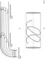
- Fig. 4a and 4b show an exemplary view of a non-axisymmetric flow profile
- Fig. 4b on the other hand, an exemplary representation of a swirling flow, which is generated by a Fig. 4a This can be caused by the pipe run shown.
- Pipe bends, valves, and other pipe fittings cause inlet disturbances before the measuring point. With a simple pipe bend, a symmetrical flow profile changes into a non-axisymmetric profile, see Fig. 4a .
- a twist can also occur, which can change its profile formation depending on the speed, as in Fig. 4b shown.
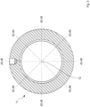
- Fig. 5 shows an arrangement by which inlet disturbances present upstream of the measuring point can be calculated from the measurement result.
- the view shows the positioning of the sensors 42, 48 for recording the differential pressure measurement across the circumference of the pipe.
- the arrangement of two or more sensors 42, 48 distributed around the circumference of the measuring pipe results in dynamic measurement data acquisition across multiple paths.
- the automatic zero point correction process can also be verified.
- the differential pressure transmitter's zero point correction is performed in the installed state by disconnecting it from the process and opening the compensation line via the manual valve block.
- this correction can be easily performed when the process fluid is at rest.
- One sensor monitors whether the process fluid is moving while the other sensor is performing its zero point correction. Manual intervention is no longer necessary.
- Fig. 6b shows an example of a corresponding procedure.
Landscapes
- Physics & Mathematics (AREA)
- General Physics & Mathematics (AREA)
- Fluid Mechanics (AREA)
- Biochemistry (AREA)
- Chemical & Material Sciences (AREA)
- Analytical Chemistry (AREA)
- Life Sciences & Earth Sciences (AREA)
- General Health & Medical Sciences (AREA)
- Health & Medical Sciences (AREA)
- Immunology (AREA)
- Pathology (AREA)
- Electromagnetism (AREA)
- Acoustics & Sound (AREA)
- Measuring Fluid Pressure (AREA)
Priority Applications (1)
| Application Number | Priority Date | Filing Date | Title |
|---|---|---|---|
| EP23195480.1A EP4521072B1 (fr) | 2023-09-05 | 2023-09-05 | Transmetteur de pression active pour mesurer des courants de fluides gazeux et liquides et procédé correspondant |
Applications Claiming Priority (1)
| Application Number | Priority Date | Filing Date | Title |
|---|---|---|---|
| EP23195480.1A EP4521072B1 (fr) | 2023-09-05 | 2023-09-05 | Transmetteur de pression active pour mesurer des courants de fluides gazeux et liquides et procédé correspondant |
Publications (3)
| Publication Number | Publication Date |
|---|---|
| EP4521072A1 true EP4521072A1 (fr) | 2025-03-12 |
| EP4521072B1 EP4521072B1 (fr) | 2026-02-18 |
| EP4521072C0 EP4521072C0 (fr) | 2026-02-18 |
Family
ID=87933913
Family Applications (1)
| Application Number | Title | Priority Date | Filing Date |
|---|---|---|---|
| EP23195480.1A Active EP4521072B1 (fr) | 2023-09-05 | 2023-09-05 | Transmetteur de pression active pour mesurer des courants de fluides gazeux et liquides et procédé correspondant |
Country Status (1)
| Country | Link |
|---|---|
| EP (1) | EP4521072B1 (fr) |
Citations (4)
| Publication number | Priority date | Publication date | Assignee | Title |
|---|---|---|---|---|
| US20160320219A1 (en) * | 2013-12-27 | 2016-11-03 | Tecom As | Sensor apparatus |
| DE102017001049A1 (de) | 2017-02-06 | 2018-08-09 | EEE Anlagenbau GmbH | Wirkdruckgeber |
| GB2571405A (en) * | 2018-12-13 | 2019-08-28 | Hevasure Ltd | Optical corrosion sensor |
| US20220178590A1 (en) * | 2019-04-04 | 2022-06-09 | Schlumberger Technology Corporation | Geothermal production monitoring systems and related methods |
-
2023
- 2023-09-05 EP EP23195480.1A patent/EP4521072B1/fr active Active
Patent Citations (4)
| Publication number | Priority date | Publication date | Assignee | Title |
|---|---|---|---|---|
| US20160320219A1 (en) * | 2013-12-27 | 2016-11-03 | Tecom As | Sensor apparatus |
| DE102017001049A1 (de) | 2017-02-06 | 2018-08-09 | EEE Anlagenbau GmbH | Wirkdruckgeber |
| GB2571405A (en) * | 2018-12-13 | 2019-08-28 | Hevasure Ltd | Optical corrosion sensor |
| US20220178590A1 (en) * | 2019-04-04 | 2022-06-09 | Schlumberger Technology Corporation | Geothermal production monitoring systems and related methods |
Also Published As
| Publication number | Publication date |
|---|---|
| EP4521072B1 (fr) | 2026-02-18 |
| EP4521072C0 (fr) | 2026-02-18 |
Similar Documents
| Publication | Publication Date | Title |
|---|---|---|
| EP3428583B1 (fr) | Procédé de fonctionnement d'un compteur de fluide et compteur de fluide | |
| EP0046965A1 (fr) | Procédé et appareil pour la détermination dynamique du débit massique independant de la densité | |
| DE102013106157A1 (de) | Meßsystem mit einem Druckgerät sowie Verfahren zur Überwachung und/oder Überprüfung eines solchen Druckgeräts | |
| DE102013106155A1 (de) | Meßsystem mit einem Druckgerät sowie Verfahren zur Überwachung und/oder Überprüfung eines solchen Druckgeräts | |
| EP3721176B1 (fr) | Procédé de surveillance du fonctionnement d'un compteur de fluide et compteur de fluide | |
| DE102004053142A1 (de) | Flanschwirbeldurchflußmesser mit unitären zulaufenden Erweiterungsstücken | |
| EP3273205B1 (fr) | Procédé et système de débitmetre à ultrasons clamp-on et corps destiné à réaliser la mesure | |
| DE102015111642A1 (de) | Durchflussmessgerät nach dem Wirbelzählerprinzip | |
| EP2812659B1 (fr) | Débitmètre à ultrasons et procédé destinés à déterminer la vitesse d'écoulement ou encore le débit volumique d'un fluide | |
| DE102014114858A1 (de) | Bunkermesssystem | |
| DE10229925A1 (de) | Vorrichtung zum Messen der Strömungsgeschwindigkeit und/oder des Durchflusses eines Fluids | |
| DE10254053A1 (de) | Verfahren und Vorrichtung zur Bestimmung und/oder Überwachung eines Volumen- und/oder Massenstroms | |
| DE102008013224A1 (de) | Messsystem und Verfahren zur Bestimmung und/oder Überwachung eines Durchflusses eines Messmediums durch ein Messrohr | |
| DE102017001049A1 (de) | Wirkdruckgeber | |
| WO2014191136A1 (fr) | Dispositif pour déterminer et/ou surveiller le débit volumique et/ou massique d'un fluide | |
| DE102007053105B4 (de) | Verfahren und Vorrichtung zur Volumenstrommessung von Fluiden in Rohrleitungen | |
| EP4521072B1 (fr) | Transmetteur de pression active pour mesurer des courants de fluides gazeux et liquides et procédé correspondant | |
| EP3715797B1 (fr) | Débitmètre à ultrasons, procédé de fonctionnement d'un débitmètre à ultrasons, ensemble de mesure et procédé de fonctionnement d'un ensemble de mesure | |
| EP2581714B1 (fr) | Procédé et dispositif de détermination d'une vitesse d'écoulement absolue d'un flux massique ou volumique | |
| DE102006039489B3 (de) | Verfahren zur Messung von Geschwindigkeitsverteilungen eines durch einen Rohrquerschnitt strömenden Fluids und Messanordnung zur Durchführung des Verfahrens | |
| EP1664738A1 (fr) | Dispositif de mesure de particule | |
| DE102009035983A1 (de) | Verfahren und Vorrichtung zur Bestimmung einer Durchflussmenge eines Fluids | |
| DE102007061585A1 (de) | Verfahren und Einrichtung zum Kompensieren von die Messgenauigkeit störenden Druckeinflüssen bei Coriolis-Durchflussmessgeräten | |
| DE102015106187A1 (de) | Verfahren und Vorrichtung zur Messung des Füllstands | |
| EP1236024B1 (fr) | Procede et dispositif pour mesurer le debit de gaz et de liquides |
Legal Events
| Date | Code | Title | Description |
|---|---|---|---|
| PUAI | Public reference made under article 153(3) epc to a published international application that has entered the european phase |
Free format text: ORIGINAL CODE: 0009012 |
|
| STAA | Information on the status of an ep patent application or granted ep patent |
Free format text: STATUS: REQUEST FOR EXAMINATION WAS MADE |
|
| 17P | Request for examination filed |
Effective date: 20240822 |
|
| AK | Designated contracting states |
Kind code of ref document: A1 Designated state(s): AL AT BE BG CH CY CZ DE DK EE ES FI FR GB GR HR HU IE IS IT LI LT LU LV MC ME MK MT NL NO PL PT RO RS SE SI SK SM TR |
|
| REG | Reference to a national code |
Ref country code: DE Free format text: PREVIOUS MAIN CLASS: G01F0001325000 Ref country code: DE Ref legal event code: R079 Ref document number: 502023003065 Country of ref document: DE Free format text: PREVIOUS MAIN CLASS: G01F0001325000 Ipc: G01F0001360000 |
|
| GRAP | Despatch of communication of intention to grant a patent |
Free format text: ORIGINAL CODE: EPIDOSNIGR1 |
|
| STAA | Information on the status of an ep patent application or granted ep patent |
Free format text: STATUS: GRANT OF PATENT IS INTENDED |
|
| RIC1 | Information provided on ipc code assigned before grant |
Ipc: G01N 29/22 20060101ALI20250326BHEP Ipc: G01N 29/024 20060101ALI20250326BHEP Ipc: G01N 21/88 20060101ALI20250326BHEP Ipc: G01N 21/55 20140101ALI20250326BHEP Ipc: G01F 15/02 20060101ALI20250326BHEP Ipc: G01F 1/74 20060101ALI20250326BHEP Ipc: G01F 1/667 20220101ALI20250326BHEP Ipc: G01F 1/661 20220101ALI20250326BHEP Ipc: G01F 1/66 20220101ALI20250326BHEP Ipc: G01F 1/325 20220101ALI20250326BHEP Ipc: G01F 1/44 20060101ALI20250326BHEP Ipc: G01F 1/36 20060101AFI20250326BHEP |
|
| INTG | Intention to grant announced |
Effective date: 20250410 |
|
| GRAJ | Information related to disapproval of communication of intention to grant by the applicant or resumption of examination proceedings by the epo deleted |
Free format text: ORIGINAL CODE: EPIDOSDIGR1 |
|
| STAA | Information on the status of an ep patent application or granted ep patent |
Free format text: STATUS: REQUEST FOR EXAMINATION WAS MADE |
|
| INTC | Intention to grant announced (deleted) | ||
| GRAP | Despatch of communication of intention to grant a patent |
Free format text: ORIGINAL CODE: EPIDOSNIGR1 |
|
| STAA | Information on the status of an ep patent application or granted ep patent |
Free format text: STATUS: GRANT OF PATENT IS INTENDED |
|
| INTG | Intention to grant announced |
Effective date: 20250917 |
|
| GRAS | Grant fee paid |
Free format text: ORIGINAL CODE: EPIDOSNIGR3 |
|
| GRAA | (expected) grant |
Free format text: ORIGINAL CODE: 0009210 |
|
| STAA | Information on the status of an ep patent application or granted ep patent |
Free format text: STATUS: THE PATENT HAS BEEN GRANTED |
|
| AK | Designated contracting states |
Kind code of ref document: B1 Designated state(s): AL AT BE BG CH CY CZ DE DK EE ES FI FR GB GR HR HU IE IS IT LI LT LU LV MC ME MK MT NL NO PL PT RO RS SE SI SK SM TR |
|
| REG | Reference to a national code |
Ref country code: CH Ref legal event code: F10 Free format text: ST27 STATUS EVENT CODE: U-0-0-F10-F00 (AS PROVIDED BY THE NATIONAL OFFICE) Effective date: 20260218 Ref country code: GB Ref legal event code: FG4D Free format text: NOT ENGLISH |
|
| REG | Reference to a national code |
Ref country code: IE Ref legal event code: FG4D Free format text: LANGUAGE OF EP DOCUMENT: GERMAN |
|
| REG | Reference to a national code |
Ref country code: DE Ref legal event code: R096 Ref document number: 502023003065 Country of ref document: DE |
|
| U01 | Request for unitary effect filed |
Effective date: 20260318 |
|
| U07 | Unitary effect registered |
Designated state(s): AT BE BG DE DK EE FI FR IT LT LU LV MT NL PT RO SE SI Effective date: 20260324 |