EP4521376A1 - Alarmvorrichtung zur ausgabe einer warnmeldung in gegenwart von frequenzinterferenz - Google Patents
Alarmvorrichtung zur ausgabe einer warnmeldung in gegenwart von frequenzinterferenz Download PDFInfo
- Publication number
- EP4521376A1 EP4521376A1 EP23306493.0A EP23306493A EP4521376A1 EP 4521376 A1 EP4521376 A1 EP 4521376A1 EP 23306493 A EP23306493 A EP 23306493A EP 4521376 A1 EP4521376 A1 EP 4521376A1
- Authority
- EP
- European Patent Office
- Prior art keywords
- clock
- alarm device
- instant
- cellular network
- message
- Prior art date
- Legal status (The legal status is an assumption and is not a legal conclusion. Google has not performed a legal analysis and makes no representation as to the accuracy of the status listed.)
- Pending
Links
Images


Classifications
-
- G—PHYSICS
- G08—SIGNALLING
- G08B—SIGNALLING SYSTEMS, e.g. PERSONAL CALLING SYSTEMS; ORDER TELEGRAPHS; ALARM SYSTEMS
- G08B25/00—Alarm systems in which the location of the alarm condition is signalled to a central station, e.g. fire or police telegraphic systems
- G08B25/01—Alarm systems in which the location of the alarm condition is signalled to a central station, e.g. fire or police telegraphic systems characterised by the transmission medium
- G08B25/08—Alarm systems in which the location of the alarm condition is signalled to a central station, e.g. fire or police telegraphic systems characterised by the transmission medium using communication transmission lines
-
- G—PHYSICS
- G08—SIGNALLING
- G08B—SIGNALLING SYSTEMS, e.g. PERSONAL CALLING SYSTEMS; ORDER TELEGRAPHS; ALARM SYSTEMS
- G08B29/00—Checking or monitoring of signalling or alarm systems; Prevention or correction of operating errors, e.g. preventing unauthorised operation
- G08B29/02—Monitoring continuously signalling or alarm systems
- G08B29/04—Monitoring of the detection circuits
- G08B29/046—Monitoring of the detection circuits prevention of tampering with detection circuits
-
- G—PHYSICS
- G08—SIGNALLING
- G08B—SIGNALLING SYSTEMS, e.g. PERSONAL CALLING SYSTEMS; ORDER TELEGRAPHS; ALARM SYSTEMS
- G08B29/00—Checking or monitoring of signalling or alarm systems; Prevention or correction of operating errors, e.g. preventing unauthorised operation
- G08B29/18—Prevention or correction of operating errors
- G08B29/20—Calibration, including self-calibrating arrangements
-
- H—ELECTRICITY
- H04—ELECTRIC COMMUNICATION TECHNIQUE
- H04K—SECRET COMMUNICATION; JAMMING OF COMMUNICATION
- H04K3/00—Jamming of communication; Counter-measures
- H04K3/20—Countermeasures against jamming
- H04K3/22—Countermeasures against jamming including jamming detection and monitoring
-
- H—ELECTRICITY
- H04—ELECTRIC COMMUNICATION TECHNIQUE
- H04K—SECRET COMMUNICATION; JAMMING OF COMMUNICATION
- H04K3/00—Jamming of communication; Counter-measures
- H04K3/20—Countermeasures against jamming
- H04K3/22—Countermeasures against jamming including jamming detection and monitoring
- H04K3/224—Countermeasures against jamming including jamming detection and monitoring with countermeasures at transmission and/or reception of the jammed signal, e.g. stopping operation of transmitter or receiver, nulling or enhancing transmitted power in direction of or at frequency of jammer
- H04K3/226—Selection of non-jammed channel for communication
-
- H—ELECTRICITY
- H04—ELECTRIC COMMUNICATION TECHNIQUE
- H04K—SECRET COMMUNICATION; JAMMING OF COMMUNICATION
- H04K3/00—Jamming of communication; Counter-measures
- H04K3/80—Jamming or countermeasure characterized by its function
- H04K3/88—Jamming or countermeasure characterized by its function related to allowing or preventing alarm transmission
-
- H—ELECTRICITY
- H04—ELECTRIC COMMUNICATION TECHNIQUE
- H04K—SECRET COMMUNICATION; JAMMING OF COMMUNICATION
- H04K2203/00—Jamming of communication; Countermeasures
- H04K2203/10—Jamming or countermeasure used for a particular application
- H04K2203/16—Jamming or countermeasure used for a particular application for telephony
-
- H—ELECTRICITY
- H04—ELECTRIC COMMUNICATION TECHNIQUE
- H04M—TELEPHONIC COMMUNICATION
- H04M11/00—Telephonic communication systems specially adapted for combination with other electrical systems
- H04M11/04—Telephonic communication systems specially adapted for combination with other electrical systems with alarm systems, e.g. fire, police or burglar alarm systems
Definitions
- the present invention belongs to the field of alarm devices (devices for detecting intrusion into an area to be protected). More particularly, the invention relates to an alarm device adapted to transmit an alert message to a cellular network in the presence of interference of the cellular network frequencies.
- Alarm systems are typically equipped with infrared or radar sensors to detect intrusion into the area to be protected. In response to intrusion detection, the system can trigger deterrents (e.g., a siren or smoke generator) and send an alert message to a remote monitoring server.
- deterrents e.g., a siren or smoke generator
- the alert message is usually sent over a cellular wireless communication network, such as an LTE network (Long Term Evolution, the fourth generation, or 4G, standard specified by the 3GPP consortium) or a 5G-NR network (5G - New Radio, the fifth generation 3GPP standard).
- a cellular wireless communication network such as an LTE network (Long Term Evolution, the fourth generation, or 4G, standard specified by the 3GPP consortium) or a 5G-NR network (5G - New Radio, the fifth generation 3GPP standard).
- a jammer is a radio transmitter designed to jam, disrupt, or block radiocommunication signals. It generally works by emitting a noise signal at a higher radio power level than the useful signals, on one or more frequency bands. The useful signals are then no longer detected by receivers.
- a particular wireless communication network which uses techniques of radio transmission that are not very sensitive to frequency interference.
- This may in particular be an LPWAN type network (acronym for "Low Power Wide Area Network") which uses the ultra-narrow band (UNB) communication technique.
- the patent EP 3 477 611 B1 gives an example of an alarm device comprising a radio communication module configured to send an alert message to an LPWAN network in one-way mode when radio jamming is detected.
- LPWAN network implementing jamming-resistant radio technology is not always available. In such a case, it is necessary to use a cellular network to transmit the alert message.
- cellular networks are two-way, which means that a terminal and a base station of the cellular network must be synchronized in time and frequency to communicate. Also, the terminal must receive a message from the base station on a downlink to obtain radio resources to use on an uplink to transmit a message. However, in the case of frequency interference at the terminal, the latter will not be able to receive the resource allocation message for transmitting the alert message.
- the present invention aims to remedy all or part of the drawbacks of the prior art, in particular those set out above.
- the invention may further comprise one or more of the following characteristics, taken individually or in any technically possible combination.
- the cellular network is an LTE or 5G-NR network supporting the "PUR" procedure defined by the 3GPP R16 specification;
- the preconfigured radio resources are defined by a "PUR” configuration received by the alarm device in a connection release message, "RRC Release”, transmitted by a station of the cellular network;
- the alert message is transmitted by the alarm device on an uplink shared channel, "(N)PUSCH", independently of a condition relating to the received power level of a reference signal, "(N)RSRP", or to a time advance, "TA”, for said station.
- the cellular network is a 5G-NR network supporting the “CG-SDT Type 1” procedure defined by the 3GPP R17 specification;
- the preconfigured radio resources are defined by a “CG-SDT Type 1” configuration received by the alarm device in a connection release message, “RRC Release”, transmitted by a station of the cellular network;
- the alert message is transmitted by the alarm device on an uplink shared channel, “(N)PUSCH”, independently of a condition relating to the received power level of a reference signal, “(N)RSRP”, or to a time advance, “TA”, for said station.
- the cellular network is a 5G-NR network supporting the two-steps RA-SDT procedure for transmitting a short packet on a random access channel, defined by the 3GPP R17 specification;
- the preconfigured radio resources are defined by a PRACH configuration received by the alarm device in a system information message, SIB1, transmitted by a station of the cellular network;
- the alert message is transmitted by the alarm device on a random access channel, (N)PRACH, independently of a condition relating to the received power level of a reference signal, (N)RSRP, for said station.
- the preconfigured radio resources define several transmission opportunities at several future times, and the alert message is issued repeatedly at several of said future times.
- said at least one calibration instant is defined by the alarm device as a function of a maximum drift duration, said maximum drift duration being predefined as a function of the duration of a cyclic prefix present in a frame of the cellular network and as a function of a level accuracy of the alarm device clock.
- the invention may further comprise one or more of the following features, taken individually or in any technically possible combination.
- the communication module is configured to receive the preconfigured radio resources in a “PUR” configuration included in a connection release message, “RRC Release”, transmitted by a station of the cellular network.
- the communication module is configured to transmit the alert message on an uplink shared channel, “(N)PUSCH”, regardless of a condition relating to the received power level of a reference signal, “(N)RSRP”, or to a time advance, “TA”, for said station.
- the communication module is configured to receive the preconfigured radio resources in a "CG-SDT Type 1" configuration included in a connection release message, "RRC Release", transmitted by a station of the cellular network.
- the communication module is configured to transmit the alert message on an uplink shared channel, "(N)PUSCH”, independently of a condition relating to the received power level of a reference signal, "(N)RSRP", or to a time advance, "TA", for said station.
- the communication module is configured to receive the preconfigured radio resources in a "PRACH” configuration included in a system information message, "SIB1", transmitted by a station of the cellular network.
- the communication module is configured to transmit the alert message on a random access channel, "(N)PRACH”, independently of a condition relating to the received power level of a reference signal, "(N)RSRP", for said station.
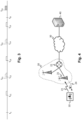
- FIG. 1 And 2 schematically represent the main steps of an example of implementation of a method 100 according to the invention to enable an alarm device to emit an alert message even in the presence of frequency interference.
- Figure 4 represents the transmission of an alert message by an alarm device 10 to a remote monitoring server 40 via a cellular network 20. The alert message is transmitted on an uplink 23 from the alarm device 10 to the cellular network 20.
- the alarm device 10 is for example designed to detect and signal an unauthorized intrusion into an area to be protected. This may be an outdoor area (enclosure, courtyard, garden, etc.) or an indoor area (house, apartment, room of a building, etc.).
- the remote monitoring server 40 is for example implemented by a remote monitoring operator to trigger actions in response to the alert message (establishing communication with a manager of the protected area in which the intrusion took place, sending a security agent to the area, etc.). Communication between the alarm device 10 and the remote monitoring server 40 is established via the cellular network 20.
- This cellular network 20 is a wireless communication network which acts as a radio access network (RAN) to a core network 30 (for example the Internet network) to which the remote monitoring server 40 is connected.
- RAN radio access network
- the cellular network 20 corresponds, for example, to an LTE network, a 5G-NR network, or a sixth-generation (6G) 3GPP network. It may be a cellular network for connected objects (IoT for “Internet of Things” in English, “internet of objects” in French), such as example an LTE-M (or LTE-CAT-M for “LTE category M”) or NB-loT (acronym for “Narrow-Band loT”) type network. LTE-M and NB-loT are variations of LTE and 5G-NR networks for the IoT. As illustrated schematically in the Figure 4 , the cellular network 20 comprises base stations 21 connected to infrastructures 22 serving as gateways to the core network 30.
- the alarm device 10 is configured to implement the method 100 according to the invention.
- the alarm device 10 is configured to be able to transmit the alert message to the cellular network 20 even in the presence of interference of the frequency bands of the downlink 24 of the cellular network 20.
- the frequency jamming of the downlink 24 is represented by a cross. This means that in the presence of jamming the alarm device 10 is no longer capable of receiving a message from the cellular network 20.
- the frequency jamming is for example implemented by a malicious person to prevent the alarm device from transmitting the alert message.
- the jamming consists for example of transmitting a noise signal at a radio power level higher than the useful signals, on one or more frequency bands of the downlink 24 of the cellular network 20. The useful signals can then no longer be detected by the receivers located near the jammer.
- the jamming primarily affects the downlink 24, and does not significantly impact the uplink 23. In other words, the jamming prevents the alarm device 10 from receiving a message from the cellular network 20, but it does not prevent the cellular network 20 from receiving a message sent by the alarm device 10. However, in order to send a message to the cellular network 20, the alarm device 10 must be able to synchronize with the cellular network 20 and receive radio resources allocated by the cellular network 20. Jamming the downlink 23 therefore generally also prevents the alarm device 10 from sending a message.
- the invention described in the present application offers a solution to enable the alarm device 10 to transmit an alert message to the cellular network 20 even in the presence of interference of the frequency bands of the downlink 24 of the cellular network 20.
- the Figures 7 and 8 schematically represent exemplary embodiments of an alarm device 10 according to the invention.
- the alarm device 10 comprises in particular a communication module 11, a clock 12, a jamming detection module 13 and an intrusion detection module 14.
- the communication module 11 implements the functions allowing the alarm device 10 to communicate with the cellular network 20.
- the communication module 11 comprises software and/or hardware means configured to exchange (send and receive) messages with the cellular network 20. These means are considered to be known to those skilled in the art.
- the clock 12 is used by the communication module to synchronize time and frequency with a clock of the cellular network 20. Indeed, to be able to receive a message from the cellular network 20, or to be able to transmit a message to the cellular network 20, the communication module 11 must be able to precisely determine the start time of a communication frame.
- a communication frame lasts ten milliseconds; each frame comprises ten sub-frames; each sub-frame comprises two slots; each slot comprises seven OFDMA symbols (an acronym for “Orthogonal Frequency Division Multiple Access”, a data multiplexing and coding technique).
- Each OFDMA symbol comprises radio samples and a cyclic prefix (CP for “Cyclic Prefix” in English).
- the cyclic prefix is used as a guard interval (time margin) to maintain the orthogonality and sinusoidal properties of the signal in the case of multipaths.
- the first cyclic prefix of a communication frame has a duration of approximately 5.2 ⁇ s (microseconds); the cyclic prefixes preceding the other six symbols have a duration of approximately 4.7 ⁇ s.
- the time of transmission of a message by the alarm device 10 must generally have a precision lower than the duration of a cyclic prefix so that the message is correctly received by the cellular network 20.
- the clock 12 corresponds for example to a temperature-compensated quartz oscillator (TCXO, for “Temperature Controlled X (Crystal) Oscillator”).
- the crystal materials and manufacturing processes of the clock 12 of the alarm device 10 and the clock of the base station 21 to which the alarm device 10 is connected are different and this can cause a shift between the clocks.
- This frequency shift can also be impacted by environmental factors such as temperature or humidity.
- the jamming detection module 13 comprises software and/or hardware means for implementing the functions allowing the alarm device 10 to verify whether interference of the frequency bands of the downlink 24 of the cellular network 20 is present or not.
- the interference detection module 13 can in particular interface with the communication module 11 and/or reuse sub-modules of the communication module 11. None would also prevent, in a variant, the interference detection module from being integrated within the communication module 11.
- the alarm device 10 is configured to implement the steps of the method 100 according to the invention to be able to transmit an alert message even in the presence of jamming.
- the communication module 11, the clock 12, the jamming detection module 13 and the intrusion detection module 14 represent means configured in software and/or hardware to implement this method 100.
- the alarm device 10 may in particular comprise one or more processors and storage means (electronic memory) in which a computer program product is stored, in the form of a set of program code instructions to be executed to implement the different steps of the method 100.
- the communication module 11, the jamming detection module 13 and the intrusion detection module 14 may be implemented by a single processor, or by several separate processors.
- the alarm device 10 may comprise one or more programmable logic circuits (FPGA, PLD, etc.), and/or one or more specialized integrated circuits (ASIC), and/or a set of discrete electronic components adapted to implement the steps of the method 100.
- FPGA programmable logic circuits
- ASIC specialized integrated circuits
- the preconfigured radio resources are time and frequency radio resources for the uplink 23: they define one or more time slots and one or more frequencies to be used for the transmission of a message by the alarm device 10 to the cellular network 20.
- these may be, for example, radio resources of a physical uplink shared channel: PUSCH channel (acronym for “Physical Uplink Shared Channel”) in the case of LTE or 5G-NR, or NPUSCH channel (acronym for “Narrow-Band Physical Uplink Shared Channel”) in the specific case of LTE-M or NB-loT.
- PUSCH channel an Physical Uplink Shared Channel
- NPUSCH channel an “Narrow-Band Physical Uplink Shared Channel” in the specific case of LTE-M or NB-loT.
- These preconfigured radio resources may in particular be obtained via the “PUR” (acronym for “Preconfigured Uplink Resource”) or “CG-SDT Type 1” (for “Configured Grant Small Data Transmission Type 1”) procedures. These procedures will be described in more detail later with reference to the Figure 5 .
- the preconfigured radio resources are resources allocated specifically by the cellular network 20 for the alarm device 10 (these radio resources cannot be used by another device).
- these may be radio resources of a packet random access channel (PRACH).
- PRACH packet random access channel
- These preconfigured radio resources correspond, for example, to a PRACH configuration received by the alarm device 10 in a system information message (SIB1, for “System Information Block #1”) transmitted by the cellular network 20.
- SIB1 system information message
- These radio resources may in particular be used by the alarm device 10 in a two-step transmission procedure of a short packet on a random access channel (“2-steps RA-SDT”, for “Two-steps Random Access Small Data Transmission i”). This procedure will be described in more detail later with reference to the Figure 6 .
- the preconfigured radio resources are resources shared between several users of the cellular network 20. In other words, these radio resources are not exclusively reserved for the alarm device 10, and there may consequently be collisions between several users (one or more users may use these radio resources at the same time as the alarm device 10).
- the preconfigured radio resources can define several transmission opportunities in the future (t E1 , t E2 , t E3 ). These can be several transmission times configured by the PUR procedure or by the CG-SDT procedure, or they can be several PRACH opportunities.
- the time distance between the first instant t 1 and a future instant of transmission may be greater than a few tens of seconds, for example at least equal to thirty seconds, or even at least equal to one minute.
- the time distance between the first instant t 1 and the first future instant of transmission corresponds to at least eight hyper-frames (a hyper-frame corresponds to 1024 frames; a hyper-frame therefore has a duration of 10.24 seconds). This therefore corresponds to a time distance at least equal to 81.92 seconds.
- t C1 , t C2 , t C3 can be defined, for example with a periodic repetition.
- the calibration times can in particular be defined by the alarm device as a function of the precision of the clock 12, as a function of the duration of a cyclic prefix of a frame, and/or as a function of future transmission times (t E1 , t E2 , t E3 ).
- the calibration times are defined by the alarm device 10, and they are not specified by the standard implemented by the cellular network 20.
- steps 110 (obtaining preconfigured radio resources) and 120 (calibrating clock 12 of alarm device 10) may be iterated several times before an intrusion is detected.
- step 115 of determining a next calibration time can be repeated each time a calibration 120 of the clock 12 of the alarm device 10 is carried out, as long as no intrusion is detected.
- a new calibration 120 of the clock 12 is carried out each time a calibration moment is reached.
- the preconfigured radio resources are valid only for a predetermined duration.
- the step 110 of obtaining preconfigured radio resources can then be renewed to obtain new preconfigured radio resources.
- This renewal of the preconfigured radio resources can take place several times (potentially a large number of times) before an intrusion is detected.
- the preconfigured radio resources can become invalid if a predefined number of successive transmission occasions are not used.
- the alarm device 10 in response to the detection of an intrusion, the alarm device 10 carries out a check 130 whether frequency interference from the downlink 24 is present.
- the alert message can be transmitted in a conventional manner, for example with a four-step packet random access channel (4-steps PRACH) procedure.
- 4-steps PRACH packet random access channel
- This procedure makes it possible in particular to ensure precise synchronization between the alarm device 10 and the cellular network 20 just before the alert message is transmitted. This also makes it possible to transmit the alert message as quickly as possible (no need to reach the future transmission time defined by the preconfigured resources).
- the conventional four-step random access procedure is described below with reference to the Figure 11 .
- the alarm device 10 proceeds to a transmission 140 of the alert message at the future time (t E1 in the example of the Figure 1 , t E3 on the example of the Figure 3 ) using the preconfigured radio resources.
- this transmission 140 of the alert message is carried out without requiring the reception of a message on the downlink 24 between the instant of detection of the jamming and the instant of transmission of the alert message (the reception of such a message is not possible due to the jamming).
- the calibration step(s) 120 which have been carried out between the instant of obtaining the preconfigured radio resources and the instant of transmission of the alert message allow advantageously to compensate for the absence of precise synchronization between the alarm device 10 and the cellular network 20 just before the transmission of the alert message.
- FIG. 5 illustrates the steps of obtaining 110 the preconfigured radio resources and transmitting 140 the alert message when the method 100 is based on the “PUR” procedure or on the CG-SDT Type 1 procedure.
- the PUR procedure is defined by the 3GPP R16 (Release 16) specification.
- the CG-SDT Type 1 procedure is defined by the 3GPP R17 (Release 17) specification.
- a PUR configuration or a CG-SDT configuration can be obtained in an “RRC Release” message (connection release message) transmitted by the base station 21 of the cellular network 20 to which the alarm device 10 is connected (in response to a request previously transmitted by the alarm device 10).
- the alarm device 10 then goes into standby mode (“RRC_IDLE” mode) in the PUR case, or into inactive mode (“RRC_INACTIVE” mode) in the CG-SDT case.
- the alarm device 10 then has the possibility of transmitting an alert message at each transmission opportunity defined by the PUR or CG-SDT configuration.
- the alert message is included in a connection resume message ("RRC Resume” message) transmitted on the uplink shared channel ("PUSCH" channel or "NPUSCH” channel).
- the request message to request a PUR configuration is described in 3GPP specification 36.331 v16.0.0 in section 5.6.23.2.
- the alarm device 10 has the possibility to define the number and repetition period of the desired PUR transmission opportunities.
- the PUR configuration is defined in section 6.3.2 (or in section 6.7.3.2 for the loT case).
- the CG-SDT procedure is described for example in section 8.20.2 of the 3GPP 38.401 v17.0.0 specification, or in section 5.27 of the 3GPP 38.321 v17.0.0 specification.
- the CG-SDT configuration is defined in section 6.3.2 of the 3GPP 38.331 v17.0.0 specification. It defines in particular the number and repetition period of CG-SDT transmission opportunities.
- the 3GPP standard describes conditions to be met in relation to the validation of a timing advance (TA) between the terminal and the base station 21.
- This validation is notably based on a condition relating to a received power level of a reference signal (RSRP for Reference Signal Receive Power, or NRSRP for Narrow-Band Reference Signal Receive Power) for the base station 21.
- RSRP Reference Signal Receive Power
- NRSRP Narrow-Band Reference Signal Receive Power
- PUR procedure these conditions are notably described in section 5.3.3.1 of the 3GPP 36.331 v16.0.0 specification.
- CG-SDT procedure They are described in section 5.27.2 of the 3GPP 38.321 v17.0.0 specification.
- the alert message is emitted by the alarm device 10 independently of a condition relating to the received power level of a reference signal (RSRP, or NRSRP), or to a time advance (TA), for the base station 21.
- RSRP reference signal
- TA time advance
- the CG-SDT Type 2 procedure conditions the transmission of a message on the prior reception of a control message on the downlink 24 (DCI message, acronym for "Downlink Control Indication").
- DCI message acronym for "Downlink Control Indication”
- this DCI message cannot be received on the downlink 24.
- the CG-SDT Type 2 procedure cannot therefore be used in the event of jamming.
- FIG. 6 illustrates the steps of obtaining 110 the preconfigured radio resources and transmitting 140 the alert message when the method 100 is based on the two-step transmission procedure of a short packet on a random access channel “2-steps RA-SDT”. This procedure is defined by the 3GPP R17 (Release 17) specification.
- a PRACH configuration can be obtained in a SIB1 message transmitted by the base station 21 of the cellular network 20 to which the alarm device 10 is attached (the SIB1 message is transmitted periodically by the base station 21).
- the alert message can then be transmitted by the alarm device 10 on a random access channel (PRACH channel, or NPRACH channel in the case of loT) using the radio resources defined in the PRACH configuration.
- PRACH channel or NPRACH channel in the case of loT
- the PRACH configuration is defined in 3GPP specification 36.331 v16.0.0 in section 6.3.2. It defines, among other things, the number of PRACH opportunities available, when to transmit, and which frequencies to use.
- the classic four-step PRACH procedure (“4-step PRACH”) is described in Figure 11 .
- a terminal (UE for "User Equipment") performs contention resolution to transmit data.
- the terminal transmits a random access request message ("Msg1", "PRACH Request”).
- the access network responds to this request by transmitting a response message (“Msg2”, “PRACH Response”) allocating radio resources to the terminal that can be used for its data transmission.
- the terminal can then transmit its data, during a third step, in a data transmission message (“Msg3”, “Data Transmission”) on the PUSCH channel.
- the network transmits a message confirming the contention resolution (“Msg 4”, “Contention Resolution”).
- the terminal In the event of downlink frequency interference, the terminal cannot receive messages from the cellular network. The classic four-step PRACH procedure is therefore not possible.
- the terminal transmits its data directly in the first message, "Msg A", at the same time as the PRACH Request.
- Msg A the terminal no longer needs to receive another message from the cellular network on the downlink to be able to transmit its data.
- the message "Msg A” corresponds to the combination of the messages "Msg 1" and "Msg 3" of the classic four-step procedure.
- the cellular network then transmits a response message "Msg B" which corresponds to the combination of "Msg 2" and "Msg 4" of the classic four-step procedure (this message "Msg B" is not shown on the Figure 6 because it is not received by the alarm device 10 in case of jamming).
- the 3GPP standard describes conditions to be met relating to the received power level of the reference signal (RSRP, or NRSRP).
- the 3GPP standard recommends that the two-step random access procedure can only be used if the received power level of the reference signal is greater than a predefined threshold.
- the alert message is emitted by the alarm device 10 independently of a condition relating to the received power level of the reference signal for the base station 21. Indeed, in the presence of interference, the reference signal will be masked by the interference, and the received power level of the reference signal is not relevant.
- the “Msg A” message containing the alert message is not correctly received by the cellular network 20 because, as explained previously, the PRACH radio resources are not exclusively reserved for the alarm device 10 (there may be collisions with one or more other users who may be using these radio resources at the same time as the device alarm 10).
- the PRACH radio resources are not exclusively reserved for the alarm device 10 (there may be collisions with one or more other users who may be using these radio resources at the same time as the device alarm 10).
- the 3GPP standard introduced the PUR, CG-SDT, and RA-SDT procedures to limit the energy consumption of terminals and to optimize the use of radio resources.
- the 3GPP standard does not recommend the use of these procedures to overcome the presence of downlink frequency interference. The use of these procedures to allow a terminal to transmit even in the presence of frequency interference is therefore particularly unexpected.
- the step 130 of verifying whether interference is present may in particular comprise a division of at least one frequency band of the downlink 24 of the cellular network 20 into several frequency sub-bands, and a measurement, for each frequency sub-band, of a received radio power level (RSSI for “Received Signal Strength Indication”).
- RSSI received radio power level
- a jamming detection criterion may then be evaluated based on the measurements obtained. For example, the jamming detection criterion is satisfied if the RSSI of at least one sub-band is greater than a threshold, or if the average of the RSSIs of the different sub-bands is greater than a threshold.
- the width of a frequency band of the downlink 24 of the cellular network 20 may in fact correspond to several tens of megahertz, for example 30 MHz, and it is advantageous to divide it into narrower sub-bands, for example 1 MHz sub-bands, or even 180 kHz sub-bands, in order to obtain individual RSSIs representative of the different sub-bands. If only a few sub-bands have an abnormally high power level, it is possible that this is simply due to network overload. On the other hand, if a very large proportion of the sub-bands have an abnormally high power level, it is likely that this is due to interference.
- FIG. 7 represents a first exemplary embodiment of an alarm device 10 according to the invention, in which the clock 12 is a 32 MHz TCXO having an accuracy of 0.1 parts per million (ppm).
- the clock 12 is a 32 MHz TCXO having an accuracy of 0.1 parts per million (ppm).
- ppm parts per million
- This error being greater than the duration of the cyclic prefix of an OFDMA slot, it could make it impossible for the cellular network 20 to correctly decode a message transmitted by the alarm device 10. This is the reason why one or more calibration steps 120 must be carried out between the time t 1 of obtaining the preconfigured radio resources and the time t E1 of transmission of the alert message, in order to maintain precise synchronization between the alarm device 10 and the cellular network 20 (or in other words to correct the drift of the clock 12). In particular, it is possible to define a maximum allowed drift duration based on the duration of a cyclic prefix and the accuracy level of clock 12.
- This maximum duration corresponds, for example, to the duration after which the time error due to drift will become greater than the duration of a cyclic prefix if we consider the worst case.
- the maximum drift duration would be approximately 47 seconds if we want to ensure a time error of less than 4.7 ⁇ s. This means that a new 120 calibration of clock 12 must be performed at least every 47 seconds. For example, we can consider performing a new 120 calibration every 40 seconds.
- the synchronization frames can notably correspond to primary synchronization signal frames (PSS for “Primary Synchronization Signal”, or NPSS for “Narrow-Band Primary Synchronization Signal” in the case of IoT).
- PSS Primary Synchronization Signal
- NPSS Narrow-Band Primary Synchronization Signal
- the first frame 31 (N)PSS is received prior to the calibration time t C1 (for example at a time close to the instant t 1 of obtaining the preconfigured radio resources, or at a previous calibration instant).
- the second frame 32 (N)PSS is received at an instant close to the calibration instant t C1 (for example, this is the first (N)PSS frame received after t C1 ).
- the reference time T Ref corresponds to the number of system frames (SFN for "System Frame Number") separating the two synchronization frames multiplied by the duration of a frame.
- the clock time T H is equal to the number N T of clock ticks multiplied by the duration of a clock tick.
- the duration of a clock tick is equal to the inverse of the frequency F T of the TCXO.
- the offset ⁇ T corresponds to a difference between T Ref and T H .
- phase-locked loop (PLL) pitch of the TCXO can then be modified according to the calculated offset ⁇ T.
- a high-precision, high-frequency clock (such as that of the first embodiment described with reference to figures 7 And 9 ) is however expensive and energy-intensive. This is why a second embodiment is proposed and described with reference to figures 8 And 10
- the clock 12 is a 32 kHz TCXO with an accuracy of 0.1 ppm (i.e., it is a high-precision, low-frequency clock).
- the alarm device 10 further comprises a 32 MHz clock 15 with an accuracy of 30 ppm (i.e., it is an additional low-precision, high-frequency clock).
- the frequencies and precision characteristics given here for the clocks 12 and 15 of the alarm device 10 are in no way limiting. Other values could be envisaged.
- the terms "high precision” and “low precision” are to be considered relatively to one another. This means in particular that the precision of the high-precision clock is greater than that of the low-precision clock (for example, the precision of the high-precision clock is at least 10 times, or even at least 50 times, or even at least 100 times, greater than that of the low-precision clock).
- the terms “high frequency” and “low frequency” for example, the frequency of the high-frequency clock is at least 100 times, or even at least 500 times, or even at least 1000 times greater than that of the low-frequency clock).
- the clock time T H corresponds to the number of complete cycles of the low-frequency clock 12 carried out between t R1 and t R2 to which must be added the incomplete clock cycle completed after t R1 and the incomplete clock cycle started before t R2 .
- the duration of the incomplete clock cycle completed after t R1 is calculated based on the number N Q1 of clock ticks indicated by the clock tick counter of the high-frequency clock 15 at time t R1 . It can be calculated in the form Max 1 F T ⁇ N Q 1 F Q 0 , expression in which F Q is the frequency of the high-frequency clock.
- the duration of the incomplete clock cycle started before t R2 is calculated based on the number N Q2 of clock ticks indicated by the clock tick counter of the high-frequency clock 15 at time t R2 . It is equal to N Q 2 F Q .
- the time error due to the cumulative drift over a clock cycle of the low-frequency clock 12 remains low.
- the second embodiment described with reference to figures 8 And 10 thus allows precise synchronization to be maintained between the alarm device 10 and the cellular network 20 without having to use a high-precision high-frequency clock.
- This second embodiment is particularly advantageous for alarm devices operating with batteries or a battery.
Landscapes
- Engineering & Computer Science (AREA)
- Computer Networks & Wireless Communication (AREA)
- Signal Processing (AREA)
- Physics & Mathematics (AREA)
- General Physics & Mathematics (AREA)
- Radar, Positioning & Navigation (AREA)
- Remote Sensing (AREA)
- Computer Security & Cryptography (AREA)
- Business, Economics & Management (AREA)
- Emergency Management (AREA)
- Mobile Radio Communication Systems (AREA)
Priority Applications (2)
| Application Number | Priority Date | Filing Date | Title |
|---|---|---|---|
| EP23306493.0A EP4521376A1 (de) | 2023-09-08 | 2023-09-08 | Alarmvorrichtung zur ausgabe einer warnmeldung in gegenwart von frequenzinterferenz |
| PCT/EP2024/074639 WO2025051757A1 (fr) | 2023-09-08 | 2024-09-04 | Dispositif d'alarme adapté pour émettre un message d'alerte en présence d'un brouillage de fréquences |
Applications Claiming Priority (1)
| Application Number | Priority Date | Filing Date | Title |
|---|---|---|---|
| EP23306493.0A EP4521376A1 (de) | 2023-09-08 | 2023-09-08 | Alarmvorrichtung zur ausgabe einer warnmeldung in gegenwart von frequenzinterferenz |
Publications (1)
| Publication Number | Publication Date |
|---|---|
| EP4521376A1 true EP4521376A1 (de) | 2025-03-12 |
Family
ID=88241426
Family Applications (1)
| Application Number | Title | Priority Date | Filing Date |
|---|---|---|---|
| EP23306493.0A Pending EP4521376A1 (de) | 2023-09-08 | 2023-09-08 | Alarmvorrichtung zur ausgabe einer warnmeldung in gegenwart von frequenzinterferenz |
Country Status (2)
| Country | Link |
|---|---|
| EP (1) | EP4521376A1 (de) |
| WO (1) | WO2025051757A1 (de) |
Citations (6)
| Publication number | Priority date | Publication date | Assignee | Title |
|---|---|---|---|---|
| US20020059535A1 (en) * | 2000-11-14 | 2002-05-16 | Bekritsky Benjamin J. | Wireless clock synchronization |
| US20110151791A1 (en) * | 2009-12-21 | 2011-06-23 | James Snider | Apparatus And Method For Maintaining Communication With A Stolen Vehicle Tracking Device |
| US20110176464A1 (en) * | 2010-01-21 | 2011-07-21 | Robert Warner | Method and apparatus for low cost, long range, power efficient, wireless system with enhanced functionality |
| EP3477611B1 (de) | 2017-10-26 | 2021-07-14 | Telecom Design | Detektions- und alarmvorrichtung für alarmsystem und diese vorrichtung umfassendes alarmsystem |
| EP3920634A1 (de) * | 2019-02-15 | 2021-12-08 | LG Electronics Inc. | Verfahren zur übertragung von uplink-daten über eine vorkonfigurierte uplink-ressource in einem drahtlosen kommunikationssystem und vorrichtung dafür |
| EP4102746A1 (de) * | 2021-06-08 | 2022-12-14 | Arlo Technologies, Inc. | Detektion und verminderung von funkfrequenzstörsendung oder interferenz in einem elektronischen überwachungssystem |
-
2023
- 2023-09-08 EP EP23306493.0A patent/EP4521376A1/de active Pending
-
2024
- 2024-09-04 WO PCT/EP2024/074639 patent/WO2025051757A1/fr active Pending
Patent Citations (6)
| Publication number | Priority date | Publication date | Assignee | Title |
|---|---|---|---|---|
| US20020059535A1 (en) * | 2000-11-14 | 2002-05-16 | Bekritsky Benjamin J. | Wireless clock synchronization |
| US20110151791A1 (en) * | 2009-12-21 | 2011-06-23 | James Snider | Apparatus And Method For Maintaining Communication With A Stolen Vehicle Tracking Device |
| US20110176464A1 (en) * | 2010-01-21 | 2011-07-21 | Robert Warner | Method and apparatus for low cost, long range, power efficient, wireless system with enhanced functionality |
| EP3477611B1 (de) | 2017-10-26 | 2021-07-14 | Telecom Design | Detektions- und alarmvorrichtung für alarmsystem und diese vorrichtung umfassendes alarmsystem |
| EP3920634A1 (de) * | 2019-02-15 | 2021-12-08 | LG Electronics Inc. | Verfahren zur übertragung von uplink-daten über eine vorkonfigurierte uplink-ressource in einem drahtlosen kommunikationssystem und vorrichtung dafür |
| EP4102746A1 (de) * | 2021-06-08 | 2022-12-14 | Arlo Technologies, Inc. | Detektion und verminderung von funkfrequenzstörsendung oder interferenz in einem elektronischen überwachungssystem |
Non-Patent Citations (4)
| Title |
|---|
| 3GPP 36.331 |
| 3GPP 38.321 |
| 3GPP 38.331 |
| 3GPP 38.401 |
Also Published As
| Publication number | Publication date |
|---|---|
| WO2025051757A1 (fr) | 2025-03-13 |
Similar Documents
| Publication | Publication Date | Title |
|---|---|---|
| US9049225B2 (en) | Method and system for detecting unauthorized wireless access points using clock skews | |
| Wullems | A spoofing detection method for civilian L1 GPS and the E1-B Galileo safety of life service | |
| Medina et al. | A synchronous TDMA ultrasonic TOF measurement system for low-power wireless sensor networks | |
| WO2005025089A1 (fr) | Gestion de l’acces a un reseau de communications a acces aleatoire | |
| US12273835B2 (en) | Communication device and method of operating the same | |
| EP2708917A1 (de) | Authentifizierung von GNSS-Signale | |
| US20220007323A1 (en) | Timing adjustment mechanism for signal transmission in non-terrestrial network | |
| FR2733655A1 (fr) | Procede et systeme d'acquisition de cadencement de trames pour des systemes sans fil a acces multiple par repartition dans le temps | |
| FR2925736A1 (fr) | Procede de production d'une preuve de presence ou de fonctionnement d'une entite dans une zone identifiee pendant une duree superieure a un seuil donne, et systeme de surveillance | |
| EP4354928A1 (de) | Erkennung von angriffen auf abstandsschätzungen unter ultra-breitband knoten | |
| US20120313804A1 (en) | Method for detecting radar signals affected by interference | |
| EP3171195B1 (de) | Verfahren zur lokalisierung einer bake | |
| O'Driscoll et al. | Assisted NMA proof of concept on Android smartphones | |
| EP1558053B1 (de) | Dynamische Anpassung der Detektion von Zugriffanforderungen auf ein Mobilfunknetz abhänging von der Funkumgebung des anfordernden Komunikationsendgeräts | |
| EP4521376A1 (de) | Alarmvorrichtung zur ausgabe einer warnmeldung in gegenwart von frequenzinterferenz | |
| WO2016162649A1 (fr) | Procédé d'émission de signaux de diffusion dans un système de communication sans fil | |
| US10512054B2 (en) | Synchronization and time transfer in wireless networks and method therefor | |
| WO2005114873A1 (fr) | Determination par un terminal de communication du temps de propagation d'un signal de reference provenant d'un equipement de gestion de communications | |
| Shahid et al. | Spoofing detection performance of snapshot OSNMA under time and symbol errors | |
| EP3286938B1 (de) | Verfahren zum senden und empfangen eines rundfunksignals mit einem steuersignal und einem informationssignal | |
| WO2017025686A1 (fr) | Procédés d'analyse de ressources fréquentielles et de sélection de fréquence d'émission dans un système de communication sans fil | |
| EP1427157B1 (de) | Verfahren und Empfängersystem für Burst-Detektion mittels Kanalschätzung | |
| FR3053865A1 (fr) | Procede d’association d’un terminal avec un reseau d’acces d’un systeme de communication sans fil | |
| WO2009053402A1 (fr) | Dispositif et procede permettant d'intercepter des communications dans un reseau | |
| EP3918727B1 (de) | Drahtloses kommunikationsverfahren und -system zwischen einem sendegerät und einem empfangsgerät durch einen repeater, ohne informationsverlust über eine physikalische eigenschaft |
Legal Events
| Date | Code | Title | Description |
|---|---|---|---|
| PUAI | Public reference made under article 153(3) epc to a published international application that has entered the european phase |
Free format text: ORIGINAL CODE: 0009012 |
|
| STAA | Information on the status of an ep patent application or granted ep patent |
Free format text: STATUS: THE APPLICATION HAS BEEN PUBLISHED |
|
| AK | Designated contracting states |
Kind code of ref document: A1 Designated state(s): AL AT BE BG CH CY CZ DE DK EE ES FI FR GB GR HR HU IE IS IT LI LT LU LV MC ME MK MT NL NO PL PT RO RS SE SI SK SM TR |
|
| STAA | Information on the status of an ep patent application or granted ep patent |
Free format text: STATUS: REQUEST FOR EXAMINATION WAS MADE |
|
| 17P | Request for examination filed |
Effective date: 20250611 |