EP4521438A1 - Disjoncteur à semi-conducteurs - Google Patents
Disjoncteur à semi-conducteurs Download PDFInfo
- Publication number
- EP4521438A1 EP4521438A1 EP24159368.0A EP24159368A EP4521438A1 EP 4521438 A1 EP4521438 A1 EP 4521438A1 EP 24159368 A EP24159368 A EP 24159368A EP 4521438 A1 EP4521438 A1 EP 4521438A1
- Authority
- EP
- European Patent Office
- Prior art keywords
- operating handle
- state
- disposed
- microswitch
- circuit breaker
- Prior art date
- Legal status (The legal status is an assumption and is not a legal conclusion. Google has not performed a legal analysis and makes no representation as to the accuracy of the status listed.)
- Pending
Links
Images




Classifications
-
- H—ELECTRICITY
- H01—ELECTRIC ELEMENTS
- H01H—ELECTRIC SWITCHES; RELAYS; SELECTORS; EMERGENCY PROTECTIVE DEVICES
- H01H71/00—Details of the protective switches or relays covered by groups H01H73/00 - H01H83/00
- H01H71/10—Operating or release mechanisms
- H01H71/50—Manual reset mechanisms which may be also used for manual release
- H01H71/52—Manual reset mechanisms which may be also used for manual release actuated by lever
- H01H71/526—Manual reset mechanisms which may be also used for manual release actuated by lever the lever forming a toggle linkage with a second lever, the free end of which is directly and releasably engageable with a contact structure
-
- H—ELECTRICITY
- H01—ELECTRIC ELEMENTS
- H01H—ELECTRIC SWITCHES; RELAYS; SELECTORS; EMERGENCY PROTECTIVE DEVICES
- H01H19/00—Switches operated by an operating part which is rotatable about a longitudinal axis thereof and which is acted upon directly by a solid body external to the switch, e.g. by a hand
- H01H19/02—Details
- H01H19/10—Movable parts; Contacts mounted thereon
- H01H19/14—Operating parts, e.g. turn knob
-
- H—ELECTRICITY
- H01—ELECTRIC ELEMENTS
- H01H—ELECTRIC SWITCHES; RELAYS; SELECTORS; EMERGENCY PROTECTIVE DEVICES
- H01H19/00—Switches operated by an operating part which is rotatable about a longitudinal axis thereof and which is acted upon directly by a solid body external to the switch, e.g. by a hand
- H01H19/02—Details
- H01H19/10—Movable parts; Contacts mounted thereon
- H01H19/28—Driving mechanisms allowing angular displacement of the operating part to be effective or possible in only one direction
-
- H—ELECTRICITY
- H01—ELECTRIC ELEMENTS
- H01H—ELECTRIC SWITCHES; RELAYS; SELECTORS; EMERGENCY PROTECTIVE DEVICES
- H01H9/00—Details of switching devices, not covered by groups H01H1/00 - H01H7/00
- H01H9/54—Circuit arrangements not adapted to a particular application of the switching device and for which no provision exists elsewhere
- H01H9/548—Electromechanical and static switch connected in series
-
- H—ELECTRICITY
- H01—ELECTRIC ELEMENTS
- H01H—ELECTRIC SWITCHES; RELAYS; SELECTORS; EMERGENCY PROTECTIVE DEVICES
- H01H71/00—Details of the protective switches or relays covered by groups H01H73/00 - H01H83/00
- H01H71/10—Operating or release mechanisms
- H01H71/12—Automatic release mechanisms with or without manual release
- H01H71/46—Automatic release mechanisms with or without manual release having means for operating auxiliary contacts additional to the main contacts
-
- H—ELECTRICITY
- H01—ELECTRIC ELEMENTS
- H01H—ELECTRIC SWITCHES; RELAYS; SELECTORS; EMERGENCY PROTECTIVE DEVICES
- H01H71/00—Details of the protective switches or relays covered by groups H01H73/00 - H01H83/00
- H01H71/10—Operating or release mechanisms
- H01H71/50—Manual reset mechanisms which may be also used for manual release
- H01H71/52—Manual reset mechanisms which may be also used for manual release actuated by lever
- H01H71/522—Manual reset mechanisms which may be also used for manual release actuated by lever comprising a cradle-mechanism
- H01H71/525—Manual reset mechanisms which may be also used for manual release actuated by lever comprising a cradle-mechanism comprising a toggle between cradle and contact arm and mechanism spring acting between handle and toggle knee
Definitions
- Embodiments of the present disclosure generally relates to the field of electrical equipment, and more particularly, to a solid-state circuit breaker.
- a solid-state circuit breaker refers to a switching device that can close, carry, and open a current under a normal circuit condition, and can close, carry, and open a current under an abnormal circuit condition within a specified time.
- a conventional solid-state circuit breaker includes an operating handle, a mechanical switch, and an electronic switch. In a case that the operating handle is switched from a closing state to an opening state, the electronic switch is first opened, and the mechanical switch is then opened. In a case that the operating handle is switched from the opening state to the closing state, the mechanical switch is first closed, and the electronic switch is then closed.
- An object of the present disclosure is to provide a solid-state circuit breaker to at least partially solve the above problems.
- a solid-state circuit breaker comprising a mounting side plate; an operating handle disposed on the mounting side plate and being rotatable relative to the mounting side plate to switch between a closing state and an opening state; a mechanical switch connected to the operating handle, wherein in a case that the operating handle is rotated by a first angle from the closing state along a rotation direction of the operating handle switched from the closing state to the opening state, the operating handle drives the mechanical switch to open; an actuating assembly disposed on the mounting side plate, wherein an end of the actuating assembly abuts against the operating handle, and the actuating assembly is rotatable relative to the mounting side plate under driving of the operating handle; and a microswitch abutting against the other end of the actuating assembly away from the operating handle, wherein in a case that the operating handle is rotated by a second angle from the closing state along the rotation direction of the operating handle switched from the closing state to the opening state, the operating handle drives the actuating assembly to
- the first angle is greater than the second angle
- the operating handle is rotated from the closing state to the opening state, in a case that the operating handle is rotated by the second angle from the closing state, the operating handle can drive the actuating assembly to rotate and the microswitch is triggered by the actuating assembly, so that the current in the circuit is opened; the operating handle continues to be rotated, in a case that the operating handle is rotated by the first angle, the operating handle drives the mechanical switch to open.
- the microswitch is triggered before the mechanical switch is opened. Therefore, the mechanical switch can be opened without being charged, thereby avoiding the generation of an electric arc.
- the actuating assembly abuts against the operating handle, and the actuating assembly abuts against the microswitch, in a case that the operating handle is rotated by the second angle from the closed position, the microswitch is triggered by the actuating assembly. Therefore, the microswitch can directly and accurately capture the position of the operating handle through the actuating assembly, so that the microswitch can accurately open the circuit.
- the actuating assembly comprises a linkage part and a cam disposed at an end of the linkage part near the microswitch, the linkage part abuts against the operating handle, the cam abuts against the microswitch.
- the solid-state circuit breaker further comprises a rotating shaft, the linkage part and the cam are rotatably connected to the mounting side plate through the rotating shaft.
- the linkage part comprises a pair of linkage rods spaced apart from each other and a connecting portion disposed between the pair of linkage rods, an abutting portion is disposed on sides of the pair of linkage rods close to each other, the abutting portion abuts against the operating handle, the cam is disposed at an end of a first linkage rod of the pair of linkage rods close to the microswitch and is located on a side of the first linkage rod away from a second linkage rod of the pair of linkage rods .
- the linkage part further comprises a mounting portion and a reset spring
- the mounting portion is disposed at an end of the second linkage rod near the microswitch
- a mounting groove is disposed at an end of the mounting portion away from the cam
- the reset spring is arranged around the outer side of the rotating shaft
- an end of the reset spring is disposed within the mounting groove
- the other end is fixed inside the solid-state circuit breaker, wherein in a case that the operating handle is switched from the closing state to the opening state, the reset spring is compressed.
- the linkage part comprises a linkage rod comprising a first side and a second side disposed opposite to each other, an abutting portion is disposed on the first side, the abutting portion abuts against the operating handle, the cam is disposed at an end of the linkage rod near the microswitch and is located on the second side.
- the linkage part further comprises a mounting portion and a reset spring
- the mounting portion is disposed at an end of the linkage rod near the microswitch and extends along a direction pointing to the second side from the first side
- a mounting groove is disposed at an end of the mounting portion near the cam
- the reset spring is arranged around the outer side of the rotating shaft, an end of the reset spring is disposed within the mounting groove, the other end is fixed inside the solid-state circuit breaker, wherein in a case that the operating handle is switched from the closing state to the opening state, the reset spring is compressed.
- the cam comprises a first arc surface, a second arc surface, and a pair of transition surfaces disposed between the first arc surface and the second arc surface, arc centers of the first arc surface and the second arc surface are both located on a central axis of the rotating shaft, and a diameter of the first arc surface is greater than a diameter of the second arc surface.
- the microswitch comprises a switch arm and a switch contact abutting against the switch arm, in a case that the operating handle is in the closing state, the switch arm abuts against the second arc surface, and in a case that the operating handle is rotated by the second angle from the closing state, the switch arm abuts against the first arc surface and presses the switch contact, such that the microswitch is triggered.
- the microswitch comprises a switch arm and a switch contact abutting against the switch arm, in a case that the operating handle is in the closing state, the switch arm abuts against the first arc surface and presses the switch contact, and in a case that the operating handle is rotated by the second angle from the closing state, the switch arm abuts against the second arc surface and releases the switch contact, such that the microswitch is triggered.
- a new type of solid-state circuit breaker 100 is provided to at least partially solve the above problems.
- the principles of the present disclosure will be described in conjunction with FIGS. 1 to 13 .
- FIG. 1 shows a schematic structural diagram of the solid-state circuit breaker 100 according to some embodiments of the present disclosure, in which the operating handle 2 is in a closing state.
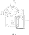
- FIG. 2 shows a schematic structural diagram of the solid-state circuit breaker 100 according to some embodiments of the present disclosure, in which the operating handle 2 is rotated by a second angle from the closing state.
- FIG. 3 shows a schematic structural diagram of the solid-state circuit breaker 100 according to some embodiments of the present disclosure, in which the operating handle 2 is rotated by a first angle from the closing state.
- FIG. 4 shows a schematic structural diagram of the solid-state circuit breaker 100 according to some embodiments of the present disclosure, in which the operating handle 2 is in the opening state.
- FIG. 1 shows a schematic structural diagram of the solid-state circuit breaker 100 according to some embodiments of the present disclosure, in which the operating handle 2 is in a closing state.
- FIG. 2 shows a schematic structural diagram of the solid-state circuit breaker 100 according to some embodiments of the present disclosure,
- the solid-state circuit breaker 100 described herein generally includes a mounting side plate 1, an operating handle 2, an actuating assembly 3, a microswitch 4, a rotating shaft 5, and a mechanical switch 6.
- the mounting side plate 1 serves as a mounting carrier for disposing the operating handle 2 and the actuating assembly 3.
- the operating handle 2 is rotatable relative to the mounting side plate 1 to switch between the closing state and the opening state.
- the operating handle 2 of the solid-state circuit breaker 100 in FIGS. 1 to 4 includes four different states among which the operating handle 2 may rotate from the closing state to the opening state.
- the operating handle 2 in FIG. 1 is in the closing state, in which the mechanical switch 6 is closed.
- the operating handle 2 in FIG. 2 rotates by the second angle from the closing state, in which the microswitch 4 is triggered by the actuating assembly 3 and the microswitch 4 transmits a signal to a Micro Control Unit (MCU).
- MCU Micro Control Unit
- the MCU receives the signal and opens the current in the circuit.
- the operating handle 2 in FIG. 3 is rotated by the first angle from the closing state, in which the mechanical switch 6 is opened.
- the operating handle 2 in FIG. 4 is in the opening state.
- the first angle is greater than the second angle, in the process of switching the operating handle 2 from the closing state to the opening state, the microswitch 4 is triggered before the mechanical switch 6 is opened. Therefore, the mechanical switch 6 can be opened without be charged, thereby avoiding generation of an electric arc at its contact position at the moment that the mechanical switch 6 is opened, which may damage the mechanical breakpoint.
- the mechanical switch 6 is connected to the operating handle 2.
- the operating handle 2 In a case that the operating handle 2 is rotated by the first angle from the closing state along a rotation direction of the operating handle 2 switched from the closing state to the opening state, the operating handle 2 drives the mechanical switch 6 to open.
- the mechanical switch 6 includes a movable contact assembly and a static contact assembly.
- the operating handle 2 is connected to the movable contact assembly through an elastic part 7 and a connecting rod 8.
- the movable contact assembly and the static contact assembly are connected, such that the mechanical switch 6 is closed.
- the operating handle 2 In a case that the operating handle 2 is rotated by the first angle from the closing state, the operating handle 2 drives the movable contact assembly to move away from the static contact assembly and separate from the static contact assembly, thereby causing the mechanical switch 6 to open.
- an end of the actuating assembly 3 abuts against the operating handle 2, and the other end abuts against the microswitch 4.
- the actuating assembly 3 is disposed on the mounting side plate 1.
- the actuating assembly 3 is rotatable relative to the mounting side plate 1 under driving of the operating handle 2.
- the operating handle 2 in a case that the operating handle 2 is rotated by a second angle from the closing state along the rotation direction of the operating handle 2 switched from the closing state to the opening state, the operating handle 2 applies a pushing force F to the actuating assembly 3.
- a lever arm L from a rotation center of the actuating assembly 3 to the pushing force F is small, and a resistance torque is small, therefore the operating handle 2 can drive the actuating assembly 3 to rotate, and the microswitch 4 is triggered by the actuating assembly 3.
- the two ends of the actuating assembly 3 respectively abuts against the operating handle 2 and the microswitch 4, therefore the microswitch 4 can directly and accurately capture the position of the operating handle 2 through the actuating assembly 3.
- the microswitch 4 is triggered by the actuating assembly 3, thereby the microswitch 4 can accurately open the circuit.
- the second angle due to the existence of the second angle, in a case that the operating handle 2 is rotated by a small angle, it is possible to avoid the microswitch 4 being triggered, thereby preventing the microswitch 4 from being mistakenly triggered.
- the angle difference is 15 °. In other embodiments, the angle difference is 20 °.
- the setting of the angle difference gives sufficient preparation time to the microswitch 4, avoiding the situation where in a case that the angle difference is too small, the microswitch 4 has not completed the action after being triggered, but the mechanical switch 6 has been opened, thereby avoiding the generation of an electric arc.
- the numbers, values, and numbers mentioned above and elsewhere in this disclosure are exemplary and are not intended to limit the scope of this disclosure in any way. Any other suitable numbers, values, and numbers are possible.
- the angle difference may include a larger or a smaller degree.
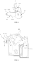
- FIG. 6 shows a schematic structural diagram of the actuating assembly 3 shown in FIGS. 1 to 5 , in which the reset spring 315 is not shown.
- the actuating assembly 3 includes a linkage part 31 and a cam 32, which are fixed with each other and rotate as a whole.
- the cam 32 is disposed at an end of the linkage part 31 near the microswitch 4.
- the linkage part 31 abuts against the operating handle 2, and the cam 32 abuts against the microswitch 4.
- the linkage part 31, the cam 32, and the mounting side plate 1 are provided with rotating holes in communication with each other, respectively.
- the rotating shaft 5 is disposed within the rotating hole so that the linkage part 31 and the cam 32 are rotatably connected to the mounting side plate 1 through the rotating shaft 5.
- the linkage part 31 includes a pair of linkage rods 311 spaced apart from each other and a connecting portion 312 disposed between the pair of linkage rods 311.
- the connecting portion 312 is used to connect the pair of linkage rods 311.
- An abutting portion 313 is disposed on sides of the pair of linkage rods close to each other. Since the operating handle 2 includes two side plates, the pair of abutting portions 313 are arranged in correspondence with and abut against the two side plates of the operating handle 2.
- the pair of linkage rods 311 include a first linkage rod 3111 and a second linkage rod 3112.
- the first linkage rod 3111 and the second linkage rod 3112 are spaced apart from each other.
- the cam 32 is disposed at an end of the first linkage rod 3111 close to the microswitch 4, and the cam 32 is located on a side of the first linkage rod 3111 away from the second linkage rod 3112.
- FIG. 7 shows a schematic structural diagram of the solid-state circuit breaker 100 shown in FIG. 1 from another perspective.
- the linkage part 31 further includes a mounting portion 314 and a reset spring 315.
- the mounting portion 314 is disposed at an end of the second linkage rod 3112 near the microswitch 4, and a mounting groove 3141 is disposed at an end of the mounting portion 314 away from the cam 32.
- the mounting groove 3141 is used to fix an end of the reset spring 315.
- An end of the rotating shaft 5 away from the cam 32 extends through the second linkage rod 3112, and the reset spring 315 is arranged around the outer side of the end of the rotating shaft 5 extending through the second linkage rod 3112.
- An end of the reset spring 315 is disposed within the mounting groove 3141, the other end is fixed to a component inside the solid-state circuit breaker 100, and the end of the rotating shaft 5 extending through the second linkage rod 3112 is located between the two ends of the reset spring 315.
- the linkage rod 311 in FIG. 7 moves downward, and the reset spring 315 is compressed by force.
- the linkage rod 311 moves upward by the force released by the reset spring 315 and abuts against the operating handle 2.
- FIG. 8 shows a schematic structural diagram of the actuating assembly 3 according to other embodiments of the present disclosure, in which the reset spring 315 is not shown.
- the number of the linkage rod 311 is one.
- the linkage rod 311 includes a first side 3113 and a second side 3114 disposed opposite to each other.
- An abutting portion 313 is disposed on the first side 3113, and the abutting portion 313 abuts against one of the side plates of the operating handle 2.
- the cam 32 is disposed at an end of the linkage rod 311 near the microswitch 4 and is located on the second side 3114.
- the linkage part 31 further includes a mounting portion 314 and a reset spring 315.
- the mounting portion 314 is disposed at an end of the linkage rod 311 near the microswitch 4 and extends along a direction pointing to the second side 3114 from the first side 3113.
- a mounting groove 3141 is disposed at an end of the mounting portion 314 near the cam 32. The mounting groove 3141 is used to fix an end of the reset spring 315.
- the reset spring 315 is arranged around an outer side of an end of the rotating shaft 5 extending through the cam 32.
- An end of the reset spring 315 is disposed within the mounting groove 3141, and the other end is fixed to a component inside the solid-state circuit breaker 100, and the end of the rotating shaft 5 extending through the cam 32 is located between the two ends of the reset spring 315.
- the linkage rod 311 in FIG. 8 moves downward, and the reset spring 315 is compressed by force.
- the operating handle 2 is switched from the opening state to the closing state, since the linkage rod 311 is not connected to the operating handle 2, the operating handle 2 cannot drive the linkage rod 311 to reset, the linkage rod 311 moves upward by the force released by the reset spring 315 and abuts against the operating handle 2.
- the microswitch 4 includes a switch arm 41 and a switch contact 42 abutting against the switch arm 41.
- the cam 32 includes a first arc surface 321, a second arc surface 322, and a pair of transition surfaces 323 disposed between the first arc surface 321 and the second arc surface 322.
- Arc centers of the first arc surface 321 and the arc centers of the second arc surface 322 are both located on the central axis of the rotating shaft 5, and a diameter of the first arc surface 321 is greater than that of the second arc surface 322.
- the first arc surface 321 of the cam 32 shown in FIGS. 1 to 4 is located below the second arc surface 322.
- the first arc surface 321 of the cam 32 can prevent the switch arm 41 of the microswitch 4 from exceeding a maximum stroke. It can be understood that in a case that the first arc surface 321 just abuts against the switch arm 41, even if the operating handle 2 continues to rotate, the switch arm 41 will not continue to press the switch contact 42, thereby avoiding deformation of the switch arm 41 of the microswitch 4.
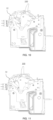
- FIG. 9 shows a schematic structural diagram of the solid-state circuit breaker 100 according to other embodiments of the present disclosure, in which the operating handle 2 is in the closing state.
- FIG. 10 shows a schematic structural diagram of the solid-state circuit breaker 100 according to other embodiments of the present disclosure, in which the operating handle 2 is rotated by the second angle from the closing state.
- FIG. 11 shows a schematic structural diagram of the solid-state circuit breaker 100 according to other embodiments of the present disclosure, in which the operating handle 2 is rotated by the first angle from the closing state.
- FIG. 12 shows a schematic structural diagram of the solid-state circuit breaker 100 according to other embodiments of the present disclosure, in which the operating handle 2 is in the opening state.
- the operating handle 2 of the solid-state circuit breaker 100 in FIGS. 9 to 12 includes four different states among which the operating handle 2 may rotate from the closing state to the opening state.
- the operating handle 2 in FIG. 9 is in the closing state, in which the mechanical switch 6 is closed.
- the operating handle 2 in FIG. 10 is rotated by the second angle from the closing state, in which the microswitch 4 is triggered and transmits a signal to the MCU.,
- the MCU receives the signal and opens the current in the circuit.
- the operating handle 2 in FIG. 11 is rotated by the first angle from the closing state, in which the mechanical switch 6 is opened.
- the operating handle 2 in FIG. 12 is in the opening state.
- FIG. 13 shows a schematic structural diagram of the actuating assembly 3 shown in FIGS. 9 to 12 , in which the reset spring 315 is not shown.
- the first arc surface 321 of the cam 32 is located above the second arc surface 322.
- the switch arm 41 abuts against the first arc surface 321, and the switch arm 41 presses the switch contact 42.
- the switch arm 41 in a case that the operating handle 2 is rotated by the second angle from the closing state, the switch arm 41 abuts against the second arc surface 322, and the switch arm 41 releases the switch contact 42, such that the microswitch 4 is triggered.
- the linkage part 31 may include a pair of linkage rods 311 spaced apart from each other and a connecting portion 312 disposed between the pair of linkage rods 311.
- the linkage part 31 may also include only one linkage rod 311, which will not be repeated here.
- the actuating assembly 3 and the microswitch 4 according to embodiments of the present disclosure can be applied to various solid-state circuit breakers 100 to accurately capture the position of the operating handle 2, such that the microswitch 4 can accurately open the circuit. It should be understood that the actuating assembly 3 and the microswitch 4 according to embodiments of the present disclosure can also be applied to other components, and embodiments of the present disclosure are not limited to this.
Landscapes
- Breakers (AREA)
- Driving Mechanisms And Operating Circuits Of Arc-Extinguishing High-Tension Switches (AREA)
Applications Claiming Priority (1)
| Application Number | Priority Date | Filing Date | Title |
|---|---|---|---|
| CN202322461890.3U CN220753249U (zh) | 2023-09-11 | 2023-09-11 | 固态断路器 |
Publications (1)
| Publication Number | Publication Date |
|---|---|
| EP4521438A1 true EP4521438A1 (fr) | 2025-03-12 |
Family
ID=90057387
Family Applications (1)
| Application Number | Title | Priority Date | Filing Date |
|---|---|---|---|
| EP24159368.0A Pending EP4521438A1 (fr) | 2023-09-11 | 2024-02-23 | Disjoncteur à semi-conducteurs |
Country Status (3)
| Country | Link |
|---|---|
| US (1) | US20250087436A1 (fr) |
| EP (1) | EP4521438A1 (fr) |
| CN (1) | CN220753249U (fr) |
Citations (8)
| Publication number | Priority date | Publication date | Assignee | Title |
|---|---|---|---|---|
| JPS6199238A (ja) * | 1984-10-22 | 1986-05-17 | 株式会社東芝 | 回路しや断器 |
| JPH0249329A (ja) * | 1988-08-10 | 1990-02-19 | Mitsubishi Electric Corp | 遮断器 |
| US6104265A (en) * | 1998-02-19 | 2000-08-15 | Eaton Corporation | Miniature circuit breaker with multipurpose auxiliary member |
| EP1487002A2 (fr) * | 2003-05-20 | 2004-12-15 | Gewiss S.P.A. | Dispositif électrique d'actionnement à distance |
| CN102376498A (zh) * | 2010-08-24 | 2012-03-14 | 上海电科电器科技有限公司 | 辅助报警开关 |
| CN113130268A (zh) * | 2021-04-21 | 2021-07-16 | 浙江中亿豪科技有限公司 | 一种带手柄驱动辅助开关的断路器 |
| FR3123142A1 (fr) * | 2021-05-20 | 2022-11-25 | Schneider Electric Industries Sas | Appareils et systèmes de protection électrique comportant un module de coupure intégré |
| CN115810519A (zh) * | 2021-09-13 | 2023-03-17 | 浙江正泰电器股份有限公司 | 一种断路器 |
-
2023
- 2023-09-11 CN CN202322461890.3U patent/CN220753249U/zh active Active
-
2024
- 2024-02-22 US US18/584,110 patent/US20250087436A1/en active Pending
- 2024-02-23 EP EP24159368.0A patent/EP4521438A1/fr active Pending
Patent Citations (8)
| Publication number | Priority date | Publication date | Assignee | Title |
|---|---|---|---|---|
| JPS6199238A (ja) * | 1984-10-22 | 1986-05-17 | 株式会社東芝 | 回路しや断器 |
| JPH0249329A (ja) * | 1988-08-10 | 1990-02-19 | Mitsubishi Electric Corp | 遮断器 |
| US6104265A (en) * | 1998-02-19 | 2000-08-15 | Eaton Corporation | Miniature circuit breaker with multipurpose auxiliary member |
| EP1487002A2 (fr) * | 2003-05-20 | 2004-12-15 | Gewiss S.P.A. | Dispositif électrique d'actionnement à distance |
| CN102376498A (zh) * | 2010-08-24 | 2012-03-14 | 上海电科电器科技有限公司 | 辅助报警开关 |
| CN113130268A (zh) * | 2021-04-21 | 2021-07-16 | 浙江中亿豪科技有限公司 | 一种带手柄驱动辅助开关的断路器 |
| FR3123142A1 (fr) * | 2021-05-20 | 2022-11-25 | Schneider Electric Industries Sas | Appareils et systèmes de protection électrique comportant un module de coupure intégré |
| CN115810519A (zh) * | 2021-09-13 | 2023-03-17 | 浙江正泰电器股份有限公司 | 一种断路器 |
Also Published As
| Publication number | Publication date |
|---|---|
| US20250087436A1 (en) | 2025-03-13 |
| CN220753249U (zh) | 2024-04-09 |
Similar Documents
| Publication | Publication Date | Title |
|---|---|---|
| CA2133059C (fr) | Mecanisme d'entrainement pour disjoncteurs | |
| US4578551A (en) | Operating mechanism for electrical switches | |
| EP2143118B1 (fr) | Système de désolidarisation d'actionneur de moteur détectant la position de l'arbre à cames | |
| EP4521438A1 (fr) | Disjoncteur à semi-conducteurs | |
| CN217955729U (zh) | 一种隔离开关操作机构及隔离开关 | |
| CN208548329U (zh) | 断路器的操作机构及断路器 | |
| CN1881495B (zh) | 带有可转动锁定装置的电开关设备的致动器 | |
| CN218939569U (zh) | 一种电动传动机构及断路器 | |
| CA1276960C (fr) | Mecanisme d'actionnement de commutateur a dispositif d'armement ameliore | |
| CN213816030U (zh) | 一种操作机构和断路器 | |
| CN216957936U (zh) | 动触头操作机构和断路器 | |
| CN114823212A (zh) | 一种隔离开关操作机构及隔离开关 | |
| CN212392175U (zh) | 一种断路器的操作机构及断路器 | |
| CN110379685B (zh) | 一种柔性脱扣结构 | |
| CN210925923U (zh) | 断路器及其弹簧操动机构的防误合装置 | |
| CN216084664U (zh) | 一种防止合闸误操作的联锁装置 | |
| CN217485382U (zh) | 操作机构和断路器 | |
| CN221508003U (zh) | 电气开关 | |
| CN221573747U (zh) | 电气开关 | |
| CN224005797U (zh) | 操作机构和隔离开关 | |
| CN223993220U (zh) | 用于降低合闸冲击的保持装置及双电源转换开关 | |
| EP4270439A1 (fr) | Interrupteur de refermeture capable d'ouvrir et de fermer de manière stable | |
| CN113012954B (zh) | 三工位操作机构及具有其的开关设备 | |
| EP4675666A1 (fr) | Disjoncteur | |
| CN222785240U (zh) | 一种双电源转换开关的操作机构 |
Legal Events
| Date | Code | Title | Description |
|---|---|---|---|
| PUAI | Public reference made under article 153(3) epc to a published international application that has entered the european phase |
Free format text: ORIGINAL CODE: 0009012 |
|
| STAA | Information on the status of an ep patent application or granted ep patent |
Free format text: STATUS: THE APPLICATION HAS BEEN PUBLISHED |
|
| AK | Designated contracting states |
Kind code of ref document: A1 Designated state(s): AL AT BE BG CH CY CZ DE DK EE ES FI FR GB GR HR HU IE IS IT LI LT LU LV MC ME MK MT NL NO PL PT RO RS SE SI SK SM TR |
|
| STAA | Information on the status of an ep patent application or granted ep patent |
Free format text: STATUS: REQUEST FOR EXAMINATION WAS MADE |
|
| 17P | Request for examination filed |
Effective date: 20250911 |
|
| STAA | Information on the status of an ep patent application or granted ep patent |
Free format text: STATUS: EXAMINATION IS IN PROGRESS |
|
| 17Q | First examination report despatched |
Effective date: 20260128 |