EP4521870A1 - Dissipateur thermique et dispositif de communication - Google Patents
Dissipateur thermique et dispositif de communication Download PDFInfo
- Publication number
- EP4521870A1 EP4521870A1 EP23829355.9A EP23829355A EP4521870A1 EP 4521870 A1 EP4521870 A1 EP 4521870A1 EP 23829355 A EP23829355 A EP 23829355A EP 4521870 A1 EP4521870 A1 EP 4521870A1
- Authority
- EP
- European Patent Office
- Prior art keywords
- heat dissipation
- substrate
- heat
- heat sink
- phase
- Prior art date
- Legal status (The legal status is an assumption and is not a legal conclusion. Google has not performed a legal analysis and makes no representation as to the accuracy of the status listed.)
- Pending
Links
Images



Classifications
-
- H—ELECTRICITY
- H05—ELECTRIC TECHNIQUES NOT OTHERWISE PROVIDED FOR
- H05K—PRINTED CIRCUITS; CASINGS OR CONSTRUCTIONAL DETAILS OF ELECTRIC APPARATUS; MANUFACTURE OF ASSEMBLAGES OF ELECTRICAL COMPONENTS
- H05K7/00—Constructional details common to different types of electric apparatus
- H05K7/20—Modifications to facilitate cooling, ventilating, or heating
- H05K7/2039—Modifications to facilitate cooling, ventilating, or heating characterised by the heat transfer by conduction from the heat generating element to a dissipating body
-
- H—ELECTRICITY
- H05—ELECTRIC TECHNIQUES NOT OTHERWISE PROVIDED FOR
- H05K—PRINTED CIRCUITS; CASINGS OR CONSTRUCTIONAL DETAILS OF ELECTRIC APPARATUS; MANUFACTURE OF ASSEMBLAGES OF ELECTRICAL COMPONENTS
- H05K7/00—Constructional details common to different types of electric apparatus
- H05K7/20—Modifications to facilitate cooling, ventilating, or heating
- H05K7/2029—Modifications to facilitate cooling, ventilating, or heating using a liquid coolant with phase change in electronic enclosures
-
- H—ELECTRICITY
- H10—SEMICONDUCTOR DEVICES; ELECTRIC SOLID-STATE DEVICES NOT OTHERWISE PROVIDED FOR
- H10W—GENERIC PACKAGES, INTERCONNECTIONS, CONNECTORS OR OTHER CONSTRUCTIONAL DETAILS OF DEVICES COVERED BY CLASS H10
- H10W40/00—Arrangements for thermal protection or thermal control
- H10W40/70—Fillings or auxiliary members in containers or in encapsulations for thermal protection or control
- H10W40/73—Fillings or auxiliary members in containers or in encapsulations for thermal protection or control for cooling by change of state
-
- F—MECHANICAL ENGINEERING; LIGHTING; HEATING; WEAPONS; BLASTING
- F28—HEAT EXCHANGE IN GENERAL
- F28D—HEAT-EXCHANGE APPARATUS, NOT PROVIDED FOR IN ANOTHER SUBCLASS, IN WHICH THE HEAT-EXCHANGE MEDIA DO NOT COME INTO DIRECT CONTACT
- F28D15/00—Heat-exchange apparatus with the intermediate heat-transfer medium in closed tubes passing into or through the conduit walls ; Heat-exchange apparatus employing intermediate heat-transfer medium or bodies
- F28D15/02—Heat-exchange apparatus with the intermediate heat-transfer medium in closed tubes passing into or through the conduit walls ; Heat-exchange apparatus employing intermediate heat-transfer medium or bodies in which the medium condenses and evaporates, e.g. heat pipes
- F28D15/0233—Heat-exchange apparatus with the intermediate heat-transfer medium in closed tubes passing into or through the conduit walls ; Heat-exchange apparatus employing intermediate heat-transfer medium or bodies in which the medium condenses and evaporates, e.g. heat pipes the conduits having a particular shape, e.g. non-circular cross-section, annular
-
- F—MECHANICAL ENGINEERING; LIGHTING; HEATING; WEAPONS; BLASTING
- F28—HEAT EXCHANGE IN GENERAL
- F28D—HEAT-EXCHANGE APPARATUS, NOT PROVIDED FOR IN ANOTHER SUBCLASS, IN WHICH THE HEAT-EXCHANGE MEDIA DO NOT COME INTO DIRECT CONTACT
- F28D15/00—Heat-exchange apparatus with the intermediate heat-transfer medium in closed tubes passing into or through the conduit walls ; Heat-exchange apparatus employing intermediate heat-transfer medium or bodies
- F28D15/02—Heat-exchange apparatus with the intermediate heat-transfer medium in closed tubes passing into or through the conduit walls ; Heat-exchange apparatus employing intermediate heat-transfer medium or bodies in which the medium condenses and evaporates, e.g. heat pipes
- F28D15/0275—Arrangements for coupling heat-pipes together or with other structures, e.g. with base blocks; Heat pipe cores
-
- F—MECHANICAL ENGINEERING; LIGHTING; HEATING; WEAPONS; BLASTING
- F28—HEAT EXCHANGE IN GENERAL
- F28F—DETAILS OF HEAT-EXCHANGE AND HEAT-TRANSFER APPARATUS, OF GENERAL APPLICATION
- F28F3/00—Plate-like or laminated elements; Assemblies of plate-like or laminated elements
- F28F3/12—Elements constructed in the shape of a hollow panel, e.g. with channels
-
- H—ELECTRICITY
- H10—SEMICONDUCTOR DEVICES; ELECTRIC SOLID-STATE DEVICES NOT OTHERWISE PROVIDED FOR
- H10W—GENERIC PACKAGES, INTERCONNECTIONS, CONNECTORS OR OTHER CONSTRUCTIONAL DETAILS OF DEVICES COVERED BY CLASS H10
- H10W40/00—Arrangements for thermal protection or thermal control
- H10W40/20—Arrangements for cooling
- H10W40/22—Arrangements for cooling characterised by their shape, e.g. having conical or cylindrical projections
- H10W40/226—Arrangements for cooling characterised by their shape, e.g. having conical or cylindrical projections characterised by projecting parts, e.g. fins to increase surface area
-
- F—MECHANICAL ENGINEERING; LIGHTING; HEATING; WEAPONS; BLASTING
- F28—HEAT EXCHANGE IN GENERAL
- F28D—HEAT-EXCHANGE APPARATUS, NOT PROVIDED FOR IN ANOTHER SUBCLASS, IN WHICH THE HEAT-EXCHANGE MEDIA DO NOT COME INTO DIRECT CONTACT
- F28D21/00—Heat-exchange apparatus not covered by any of the groups F28D1/00 - F28D20/00
- F28D2021/0019—Other heat exchangers for particular applications; Heat exchange systems not otherwise provided for
- F28D2021/0028—Other heat exchangers for particular applications; Heat exchange systems not otherwise provided for for cooling heat generating elements, e.g. for cooling electronic components or electric devices
- F28D2021/0029—Heat sinks
Definitions
- the present disclosure relates to the technical field of communication, and more particularly, to a heat sink and a communication device.
- Embodiments of the present disclosure provide a heat sink and a communication device.
- an embodiment provides a heat sink, including: a heat dissipation substrate, configured for absorbing heat from a heat source, where a substrate cavity and a partition structure are arranged in the heat dissipation substrate, the partition structure is configured for dividing the substrate cavity into a plurality of substrate cavity bodies, and refrigerant working medium in every two adjacent substrate cavity bodies are not in circulation with each other; and a plurality of heat dissipation fins, connected to the heat dissipation substrate.
- an embodiment provides a communication device, including the heat sink in accordance with the first aspect.
- the present disclosure provides a heat sink and a communication device.
- the heat sink includes a heat dissipation substrate and a plurality of heat dissipation fins.
- the heat dissipation substrate is configured for absorbing heat from a heat source.
- a substrate cavity and a partition structure are arranged in the heat dissipation substrate.
- the partition structure is configured for dividing the substrate cavity into a plurality of substrate cavity bodies. Refrigerant working medium in every two adjacent substrate cavity bodies are not in circulation with each other.
- the plurality of heat dissipation fins are connected to the heat dissipation substrate.
- the design of the plurality of substrate cavity bodies in the heat dissipation substrate makes it technologically easier to meet the sealing performance of each small substrate cavity body, and dry burning, if any, occurs only in part of the substrate cavity bodies, so as not to affect the heat dissipation ability of the entire heat sink. Therefore, the reliability and redundancy of the heat sink designed with a plurality of substrate cavity bodies can be improved.
- the structures of different substrate cavity bodies can be configured according to different heat source requirements to match the heat source, so as to improve the local heat dissipation capability of the heat sink.
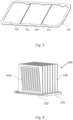
- FIG. 1 is a schematic diagram of a heat sink according to an embodiment of the present disclosure
- FIG. 2 is a cross-sectional view of a heat sink according to an embodiment of the present disclosure
- FIG. 3 is a horizontal cross-sectional view of a heat dissipation substrate of a heat sink according to an embodiment of the present disclosure.
- the heat sink 100 includes a heat dissipation substrate 110 and a plurality of heat dissipation fins 120.
- the heat dissipation substrate 110 is configured for absorbing heat from a heat source.
- a substrate cavity and a partition structure 210 are arranged in the heat dissipation substrate 110.
- the partition structure 210 is configured for dividing the substrate cavity into a plurality of substrate cavity bodies 220. Refrigerant working medium in every two adjacent substrate cavity bodies 220 are not in circulation with each other.
- the plurality of heat dissipation fins 120 are connected to the heat dissipation substrate 110.
- the design of the plurality of substrate cavity bodies 220 in the heat dissipation substrate 110 improves the reliability and redundancy of the heat sink 100.
- the structures of the substrate cavity bodies 220 can be configured according to different heat source requirements to match the heat source, so as to improve the local heat dissipation capability of the heat sink 100.
- heat dissipation fins 120 may be ordinary metal fins, or may be two-phase heat dissipation fins provided with a two-phase conduit 410 and filled with a refrigerant therein, which is not particularly limited in this embodiment.
- heat dissipation fins 120 may be connected to the heat dissipation substrate 110 by engagement, adhesion, riveting, or welding, which is not particularly limited in this embodiment.
- the partition structure 210 may be a partition plate or a partition strip, and may form an integrated or split structure with the heat dissipation substrate, which is not particularly limited in this embodiment.
- the heat dissipation fins 120 may be ordinary metal fins.
- the substrate cavity needs to be filled with a refrigerant working medium, and heat spreading is realized within a planar range of the substrate through two-phase heat transfer.
- the substrate cavity bodies 220 are filled with the refrigerant working medium, which is not particularly limited in this embodiment.
- the heat dissipation fins 120 are two-phase heat dissipation fins provided with a two-phase conduit 410 and filled with a refrigerant therein.
- two-phase heat transfer is provided both in a flat plate range (horizontal) of the heat dissipation substrate 110 and in a heat dissipation plane range (vertical) of the heat dissipation fins 120, such that the heat source on the back of the substrate can spread heat in a three-dimensional space.
- the two-phase conduit 410 of the heat dissipation fin 120 may be an independent conduit, which is independent of the substrate cavity.
- the substrate cavity and the two-phase conduit 410 of the heat dissipation fin 120 are independent two-phase circulation structures.
- the design of the substrate cavity bodies of the substrate cavity is independent of the design of the two-phase conduits 410 of the heat dissipation fins, and the substrate cavity can be designed as required.
- the two-phase conduit 410 of the heat dissipation fin 120 is an open conduit in communication with the substrate cavity of the heat dissipation substrate.
- the two-phase conduit 410 of the heat dissipation fin 120 is in communication with the substrate cavity of the heat dissipation substrate 110 to form a connected two-phase circulation structure.
- the heat sink 100 of the two-phase structure adopts the design of the plurality of substrate cavity bodies 220 in the heat dissipation substrate, it is technologically easier to meet the sealing performance of each small substrate cavity body 220 compared with the use of the design of an integrated cavity, and dry burning, if any, occurs only in part of the substrate cavity bodies 220, so as not to affect the heat dissipation ability of the entire heat sink. Therefore, the reliability and redundancy of the heat sink designed with a plurality of substrate cavity bodies 220 can be improved.
- the substrate cavity can be designed according to the position characteristics of heat source distribution, to improve the efficiency of two-phase heat dissipation.
- the mode of communication between the substrate cavity body 220 and the two-phase conduit 410 may be that one substrate cavity body 220 is independently in communication with one two-phase conduit 410, one substrate cavity body 220 is independently in communication with a plurality of two-phase conduits 410, or two substrate cavity bodies 220 are in communication with one two-phase conduit 410, which is not particularly limited in this embodiment.
- each of the substrate cavity bodies 220 forms an independent loop with the corresponding two-phase conduit 410.
- FIG. 6 when the partition structure 210 is arranged parallel to a length direction of the heat dissipation fin 120, each substrate cavity body 220 and the two-phase conduits 410 of all the heat dissipation fins 120 in the region corresponding to the substrate cavity body 220 together constitute a plurality of independent two-phase circulation regions.
- the number of two-phase conduits 410 in the two-phase heat dissipation fin may be equal to the number of the substrate cavity bodies 220 in communication with the two-phase heat dissipation fin, or may be greater than the number of the substrate cavity bodies 220 in communication with the two-phase heat dissipation fin, i.e., one heat dissipation fin 120 is provided with a plurality of two-phase conduits 410 in one substrate cavity body 220.
- a two-phase conduit 410 in this embodiment means an uninterrupted conduit, and the two-phase conduit 410 may be in various shapes, which is not particularly limited in this embodiment.
- a groove is provided on an inner cavity surface of the heat dissipation substrate 110, especially on an inner cavity surface of a heat source coverage region, to form a local liquid storage structure.
- a condensate flowing back under gravity will be stopped by the groove and thus retained in the groove.
- the condensate in the groove is heated by the heat source on the back of the substrate to quickly evaporate and take away the heat, such that the problem of dry burning in a local heat source region can be effectively alleviated.
- a groove may be provided in the region of an inner cavity surface of the substrate cavity body 220 in the heat dissipation substrate 110 corresponding to middle and upper heat sources.
- the groove can provide a liquid storage effect to retain the liquid flowing through the groove surface, such that the liquid can stay for a longer period of time and soak the inner cavity surface of the heat dissipation substrate 110 in this region, thereby alleviating the problem of dry burning on the upper part of the substrate during anti-gravity applications.
- capillary structures such as micro-channels and sintered capillaries may be provided inside the groove having the liquid storage function, to improve heat dissipation of the middle and upper heat sources of the heat dissipation substrate 110 in combination with the characteristics of the groove.
- the inner cavity surface of the heat dissipation substrate 110 is a rough surface.
- the rough surface is prepared by sandblasting and/or by cold spraying of metal particles, to form surface microstructure features that enhance boiling heat transfer.
- a region centered on the center of the heat source and having an area that is 1.5 times the area of the heat source is used as a surface treatment region, so as to achieve an objective of locally enhancing heat dissipation of a chip.
- sandblasting is a subtractive manufacturing process, in which the inner cavity surface is impacted and worn by high-speed sand particles, forming countless small pits in the corresponding area, i.e., a group of tiny pits.
- the pit is more likely to form a vaporization core and generate bubbles, which significantly increases the evaporation rate of the local refrigerant working medium.
- cold spraying of metal particles is an additive manufacturing process, in which small-sized metal particles (copper, aluminum, etc.) are impinged at high speed to attach to the inner cavity surface to form a group of tiny capillary particles. Pits of different sizes are formed between the particles, which can also increase vaporization cores. After the heat dissipation substrate 110 absorbs heat, the heat is transferred to the metal particles through the substrate. In this case, the liquid refrigerant working medium in the pits is heated by the surfaces of the powder particles, to gradually form small bubbles in the pits, thereby significantly increasing the local evaporation rate. It should be noted that surface microstructure features that enhance boiling heat transfer may also be provided inside the pits having the liquid storage function.
- the refrigerant in the substrate cavity bodies 220 of the heat dissipation substrate 110 will be heated to evaporate, resulting in a sudden increase in the pressure of the substrate cavity body 220, such that the heat dissipation substrate 110 is very likely to swell in its middle part.
- the swelling of the middle part of the heat dissipation substrate 110 will cause a connection region between the heat dissipation substrate 110 and the heat dissipation fin 120 to warp, leading to multiple deformations, damage, and failure.
- a plurality of supporting columns 1010 may be arranged in the substrate cavity to increase the structural strength of the heat sink 100.
- Supporting columns 1010 of different diameters may be used in combination to increase the structural strength as required.
- large-diameter supporting columns 1010 are arranged in the middle, and small-diameter supporting columns 1010 are arranged on two sides.
- small-diameter supporting columns 1010 are adopted in a large area, large-diameter supporting columns 1010 are adopted in a small area, and the large-diameter supporting columns and small-diameter supporting columns 1010 are arranged in a staggered manner.
- the large-diameter supporting columns 1010 are used to increase the structural strength, and the small-diameter supporting columns 1010 are used to reduce the coverage area of physical parts and increase the coverage area of the cavity, thereby increasing the structural strength and enhancing heat dissipation.
- diameters of the plurality of supporting columns 1010 may be the same or different, which may be set according to the specific structure of the heat sink 100 and will not be particularly limited in this embodiment.
- a top of the heat dissipation fin 120 may be bent to form a bent portion 1210, and the bent portions 1210 of a plurality of neighboring heat dissipation fins 120 are connected to each other to form a cover structure.
- the coverage range of the two-phase conduit 410 of the heat dissipation fin 120 is extended to the bent portion 1210, such that the cover structure participates in two-phase heat dissipation. In this way, the heat diffusion range of two-phase heat transfer can be further expanded, and the heat diffusion region is closer to an external cold source, thereby further improving the overall two-phase heat dissipation efficiency of the heat sink 100.
- a peripheral flange 1310 may be provided.
- the thickness of the peripheral flange 1310 is consistent with the welding depth, and the width of the peripheral flange 1310 is consistent with an influence range of friction stir welding. As shown in FIG. 13 , the design of the peripheral flange 1310 with a smaller thickness can reasonably reduce the structural thickness of the heat sink 100 and the external housing around the welding seam, thereby facilitating the overall lightweight design of the heat sink.
- an embodiment of the present disclosure provides a communication device.
- the communication device includes the heat sink of the above embodiments.
- the communication device can realize the embodiments of the heat sink.
- the technical means used, the technical problem solved, and the effects achieved by the communication device are the same as those of the heat sink in the above embodiment, so the details will not be repeated herein, and reference may be made to the embodiments of the heat sink.
- Embodiments of the present disclosure provide a heat sink and a communication device.
- the heat sink includes a heat dissipation substrate and a plurality of heat dissipation fins.
- the heat dissipation substrate is configured for absorbing heat from a heat source.
- a substrate cavity and a partition structure are arranged in the heat dissipation substrate.
- the partition structure is configured for dividing the substrate cavity into a plurality of substrate cavity bodies. Refrigerant working medium in every two adjacent substrate cavity bodies are not in circulation with each other.
- the plurality of heat dissipation fins are connected to the heat dissipation substrate.
- most heat sinks available in the market adopt an integrated cavity design. As such, heat sinks have a large cavity volume.
- the design of the plurality of substrate cavity bodies in the heat dissipation substrate makes it technologically easier to meet the sealing performance of each small substrate cavity body, and dry burning, if any, occurs only in part of the substrate cavity bodies, so as not to affect the heat dissipation ability of the entire heat sink. Therefore, the reliability and redundancy of the heat sink designed with a plurality of substrate cavity bodies can be improved.
- the structures of different substrate cavity bodies can be configured according to different heat source requirements to match the heat source, so as to improve the local heat dissipation capability of the heat sink.
Landscapes
- Engineering & Computer Science (AREA)
- Physics & Mathematics (AREA)
- Thermal Sciences (AREA)
- Microelectronics & Electronic Packaging (AREA)
- Mechanical Engineering (AREA)
- General Engineering & Computer Science (AREA)
- Life Sciences & Earth Sciences (AREA)
- Sustainable Development (AREA)
- Cooling Or The Like Of Electrical Apparatus (AREA)
- Cooling Or The Like Of Semiconductors Or Solid State Devices (AREA)
Applications Claiming Priority (2)
| Application Number | Priority Date | Filing Date | Title |
|---|---|---|---|
| CN202210736640.3A CN117355080A (zh) | 2022-06-27 | 2022-06-27 | 散热器及通信设备 |
| PCT/CN2023/072113 WO2024001162A1 (fr) | 2022-06-27 | 2023-01-13 | Dissipateur thermique et dispositif de communication |
Publications (2)
| Publication Number | Publication Date |
|---|---|
| EP4521870A1 true EP4521870A1 (fr) | 2025-03-12 |
| EP4521870A4 EP4521870A4 (fr) | 2025-08-20 |
Family
ID=89358060
Family Applications (1)
| Application Number | Title | Priority Date | Filing Date |
|---|---|---|---|
| EP23829355.9A Pending EP4521870A4 (fr) | 2022-06-27 | 2023-01-13 | Dissipateur thermique et dispositif de communication |
Country Status (5)
| Country | Link |
|---|---|
| US (1) | US20250344347A1 (fr) |
| EP (1) | EP4521870A4 (fr) |
| CN (1) | CN117355080A (fr) |
| AU (1) | AU2023297179B2 (fr) |
| WO (1) | WO2024001162A1 (fr) |
Families Citing this family (1)
| Publication number | Priority date | Publication date | Assignee | Title |
|---|---|---|---|---|
| CN119983873B (zh) * | 2025-02-28 | 2026-03-03 | 深圳三星通信技术研究有限公司 | 一种相变散热器 |
Family Cites Families (12)
| Publication number | Priority date | Publication date | Assignee | Title |
|---|---|---|---|---|
| CN105101751B (zh) * | 2015-07-03 | 2018-04-17 | 浙江嘉熙科技有限公司 | 热超导片式散热器及其制造方法 |
| CN105140194B (zh) * | 2015-07-03 | 2018-02-02 | 浙江嘉熙科技有限公司 | 热超导散热器及其制造方法 |
| CN109612316A (zh) * | 2018-12-12 | 2019-04-12 | 上海卫星装备研究所 | 薄壁均温板及其制造方法 |
| CN110012650A (zh) * | 2019-05-16 | 2019-07-12 | 常州恒创热管理有限公司 | 折弯式相变散热板及散热器 |
| CN110446398B (zh) * | 2019-07-19 | 2024-09-06 | 深圳兴奇宏科技有限公司 | 散热装置 |
| CN113883947A (zh) * | 2020-07-01 | 2022-01-04 | 讯凯国际股份有限公司 | 热交换器鳍片与用于制造热交换器鳍片的方法 |
| CN114501916A (zh) * | 2020-10-23 | 2022-05-13 | 中兴通讯股份有限公司 | 一种设备散热方法及散热设备 |
| CN213873936U (zh) * | 2020-12-03 | 2021-08-03 | 深圳市英维克科技股份有限公司 | 一种散热器 |
| CN214228725U (zh) * | 2020-12-11 | 2021-09-17 | 南京六九零二科技有限公司 | 一种基于铲齿工艺的蒸汽腔散热器 |
| CN114270503B (zh) * | 2021-03-17 | 2025-10-28 | 上海精智实业股份有限公司 | 用于通讯设置的散热器 |
| CN214316109U (zh) * | 2021-09-06 | 2021-09-28 | 四川科跃热传电子有限公司 | 一种分区散热片 |
| CN113865393B (zh) * | 2021-09-22 | 2023-02-03 | 上海精智实业股份有限公司 | 一种用于通讯设置的散热器 |
-
2022
- 2022-06-27 CN CN202210736640.3A patent/CN117355080A/zh active Pending
-
2023
- 2023-01-13 WO PCT/CN2023/072113 patent/WO2024001162A1/fr not_active Ceased
- 2023-01-13 US US18/867,669 patent/US20250344347A1/en active Pending
- 2023-01-13 AU AU2023297179A patent/AU2023297179B2/en active Active
- 2023-01-13 EP EP23829355.9A patent/EP4521870A4/fr active Pending
Also Published As
| Publication number | Publication date |
|---|---|
| AU2023297179A1 (en) | 2024-12-12 |
| AU2023297179B2 (en) | 2026-03-05 |
| CN117355080A (zh) | 2024-01-05 |
| US20250344347A1 (en) | 2025-11-06 |
| EP4521870A4 (fr) | 2025-08-20 |
| WO2024001162A1 (fr) | 2024-01-04 |
Similar Documents
| Publication | Publication Date | Title |
|---|---|---|
| TWI801696B (zh) | 相變散熱裝置 | |
| CN111863746B (zh) | 一种散热装置、电路板及电子设备 | |
| CN105101751B (zh) | 热超导片式散热器及其制造方法 | |
| CN205071563U (zh) | 热超导片式散热器 | |
| CN100423243C (zh) | 微型高效自循环电子冷却器 | |
| CN110595242A (zh) | 一种相变散热器 | |
| CN102121802B (zh) | 双面槽道板式脉动热管 | |
| CN106885485B (zh) | 一种热端变截面多脉动冷端热管散热器 | |
| CN110010569A (zh) | 一种用于电子芯片散热的梯度尺度孔隙烧结芯均热板换热器及其均热板换热器的制备方法 | |
| EP4521870A1 (fr) | Dissipateur thermique et dispositif de communication | |
| CN218585974U (zh) | 散热器 | |
| CN120264705A (zh) | 一种高效散热组件及电子设备 | |
| CN103822519A (zh) | 多孔表面沸腾换热强化装置及其制备方法 | |
| CN113207271A (zh) | 一种相变储能式散热器 | |
| CN202032930U (zh) | 一种双面槽道板式脉动热管 | |
| CN211291134U (zh) | 一种相变散热器 | |
| CN212463856U (zh) | 热超导散热板、散热器及5g基站设备 | |
| CN209745070U (zh) | 相变散热装置 | |
| CN115295512B (zh) | 一种高导热结构 | |
| CN220188941U (zh) | 一种用于cpu的三维散热器 | |
| JP2022011551A (ja) | ベーパーチャンバおよびベーパーチャンバの製造方法 | |
| CN215295936U (zh) | 用于5g基站散热模组的均温板 | |
| CN212463857U (zh) | 热超导散热板、散热器及5g基站设备 | |
| CN103745961B (zh) | 使用藕状多孔材料微通道模块的散热装置 | |
| CN112351642A (zh) | 一种集成泡沫金属吸液芯和翅片的散热器 |
Legal Events
| Date | Code | Title | Description |
|---|---|---|---|
| STAA | Information on the status of an ep patent application or granted ep patent |
Free format text: STATUS: THE INTERNATIONAL PUBLICATION HAS BEEN MADE |
|
| PUAI | Public reference made under article 153(3) epc to a published international application that has entered the european phase |
Free format text: ORIGINAL CODE: 0009012 |
|
| STAA | Information on the status of an ep patent application or granted ep patent |
Free format text: STATUS: REQUEST FOR EXAMINATION WAS MADE |
|
| 17P | Request for examination filed |
Effective date: 20241202 |
|
| AK | Designated contracting states |
Kind code of ref document: A1 Designated state(s): AL AT BE BG CH CY CZ DE DK EE ES FI FR GB GR HR HU IE IS IT LI LT LU LV MC ME MK MT NL NO PL PT RO RS SE SI SK SM TR |
|
| REG | Reference to a national code |
Ref country code: DE Ref legal event code: R079 Free format text: PREVIOUS MAIN CLASS: H05K0007200000 Ipc: H01L0023367000 |
|
| A4 | Supplementary search report drawn up and despatched |
Effective date: 20250718 |
|
| RIC1 | Information provided on ipc code assigned before grant |
Ipc: H01L 23/367 20060101AFI20250714BHEP Ipc: H01L 23/427 20060101ALI20250714BHEP Ipc: F28D 15/02 20060101ALI20250714BHEP Ipc: F28F 3/12 20060101ALI20250714BHEP Ipc: F28D 21/00 20060101ALN20250714BHEP |
|
| DAV | Request for validation of the european patent (deleted) | ||
| DAX | Request for extension of the european patent (deleted) | ||
| STAA | Information on the status of an ep patent application or granted ep patent |
Free format text: STATUS: EXAMINATION IS IN PROGRESS |
|
| STAA | Information on the status of an ep patent application or granted ep patent |
Free format text: STATUS: THE APPLICATION HAS BEEN WITHDRAWN |