EP4523773A1 - Lösungsmittelrückgewinnungssystem - Google Patents
Lösungsmittelrückgewinnungssystem Download PDFInfo
- Publication number
- EP4523773A1 EP4523773A1 EP23197202.7A EP23197202A EP4523773A1 EP 4523773 A1 EP4523773 A1 EP 4523773A1 EP 23197202 A EP23197202 A EP 23197202A EP 4523773 A1 EP4523773 A1 EP 4523773A1
- Authority
- EP
- European Patent Office
- Prior art keywords
- solvents
- container
- solvent
- evaporation
- evaporation chamber
- Prior art date
- Legal status (The legal status is an assumption and is not a legal conclusion. Google has not performed a legal analysis and makes no representation as to the accuracy of the status listed.)
- Withdrawn
Links
Images


Classifications
-
- B—PERFORMING OPERATIONS; TRANSPORTING
- B01—PHYSICAL OR CHEMICAL PROCESSES OR APPARATUS IN GENERAL
- B01D—SEPARATION
- B01D5/00—Condensation of vapours; Recovering volatile solvents by condensation
- B01D5/0003—Condensation of vapours; Recovering volatile solvents by condensation by using heat-exchange surfaces for indirect contact between gases or vapours and the cooling medium
-
- B—PERFORMING OPERATIONS; TRANSPORTING
- B01—PHYSICAL OR CHEMICAL PROCESSES OR APPARATUS IN GENERAL
- B01D—SEPARATION
- B01D3/00—Distillation or related exchange processes in which liquids are contacted with gaseous media, e.g. stripping
- B01D3/02—Distillation or related exchange processes in which liquids are contacted with gaseous media, e.g. stripping in boilers or stills
-
- B—PERFORMING OPERATIONS; TRANSPORTING
- B01—PHYSICAL OR CHEMICAL PROCESSES OR APPARATUS IN GENERAL
- B01D—SEPARATION
- B01D5/00—Condensation of vapours; Recovering volatile solvents by condensation
- B01D5/0057—Condensation of vapours; Recovering volatile solvents by condensation in combination with other processes
- B01D5/006—Condensation of vapours; Recovering volatile solvents by condensation in combination with other processes with evaporation or distillation
Definitions
- the invention is in the field of recovery of evaporated solvent.
- the present invention is directed to a method and system for solvent recovery.
- a well-known method for determining the fat content in milk is the Rgreete-Gottling method.
- fat is extracted from a milk sample using a mixture of one or more solvents. Subsequently, the one or more solvents are evaporated, and the amount of fat is determined gravimetrically.
- solvents with a low boiling point are typically used.
- ethyl ether is often used together with n-pentane, n-hexane, and/or petroleum ether.
- a known device for recovering evaporated gas is a rotary evaporator, in which a vacuum pump, condenser, and a cold trap are used to collect the evaporated gases.
- rotary evaporators have a number of disadvantages, making them less suitable for recovery of solvents, especially when working with routine measurements for which it is desired to process large batches of samples.
- rotary evaporators have many moving parts, e.g. for rotating the flask and for applying vacuum, which makes the equipment expensive, and sensitive for wear and maintenance.
- rotary evaporators are typically used with laboratory glassware which needs to be cleaned thoroughly between every sample, which makes running many samples cumbersome and expensive.
- An object of the present invention is to provide a method and system for the recovery of solvents that solves one or more of the problems mentioned above. It is also an object of the invention a method and system for the recovery of solvents that is effective, convenient, cost-effective and/or reliable compared to existing methods.
- the inventors have found that at least some of the above-mentioned objectives can be met when condensation of evaporated solvents vertically above the opening of a container from which solvents are evaporated is prevented. In this way, the risk of contamination of samples from condensed solvent flowing or dripping back into the container is minimized. Furthermore, by performing the method in an evaporation chamber and by relying on the pressure drop resulting from condensation of the evaporated solvents as driving force for the flow of evaporated solvent away from the container, there is less need for active suction of the evaporated solvent, making the method and system safe, convenient and the equipment less prone to failure or wear than known methods.
- the inventors also found that because the solvent vapors do not escape from the evaporation chamber, it is not necessary to perform the method in a fume hood or under an extractor fan in order to recover the evaporated solvents and prevent them from entering the environment.
- a method for recovery of evaporated solvent comprising the steps of: - providing in a chamber an open container comprising a liquid solution, the solution comprising one or more solvents; - heating the solution, thereby evaporating one or more of the solvents; - providing inside the chamber one or more cold surfaces, allowing the evaporated one or more solvents to condense on said one or more cold surfaces, wherein the one or more cold surfaces are located inside the chamber such that flow of condensed solvent from the one or more cold surfaces into the open container is prevented; and - collecting the condensed solvent.
- the open container has one or more openings.
- the open container has at least one opening at the top, in order to enable solvents to easily flow out of the open container.
- the top of the open container is defined as the side of the is facing upwards ( i.e., opposite the direction of gravity) when performing the method as described herein.
- the open container has high thermal conductivity, in order to facilitate quick heating of the solution.
- the open container is a metal container.
- the open container is disposable, meaning that cleaning of the container between samples is not needed, and cross contamination between samples can be avoided.
- the one or more cold surfaces are located inside the evaporation chamber in a such a way that flow of condensed solvent one or more cold surfaces into the open container is prevented. Examples of possible placement of cold surfaces relative to the open container are given in figure 1 .
- FIG. 1a show cold surfaces (6) of which a portion is located vertically above the opening of open container (3), which might lead to contamination and is therefore less preferred.
- the one or more cold surfaces do not extend to a location that is vertically above an opening of the open container. In this way, during execution of the method, dripping of solvent from the one or more cold surfaces into the open container can be prevented.
- Examples of cold surfaces (6) that do not extend to a location that is vertically above an opening of open container (3) are shown in figure 1c-1f .
- FIG. 1b shows an example of a cold surface (6), a portions of which is located vertically above open container (3), and wherein the cold surfaces slope downwards towards a low point that is not located vertically above a top opening of the open container (3).
- these one or more cold surfaces preferably slope downwards to a low point of the cold surface that is not vertically above a top opening of the container.
- the one or more cold surfaces (6) are located to the sides and/or below the open container (3), see for example figure 1c-1f .
- Cold surface refers to a surface that is cold enough for the evaporated solvents to condense.
- the desired temperature of the cold surfaces depends inter alia on the pressure inside the evaporation chamber, and the boiling point of the solvents.
- the one or more cold surfaces may for instance be cooled by bringing them in heat exchanging contact with a cooling fluid. Additionally or alternatively, the one or more cold surfaces can be cooled by using thermoelectric cooling, for instance using a Peltier device.
- Collecting the condensed solvent can be done by extracting the condensed solvent from the evaporation chamber through one or more outlets. After extracting the condensed solvent from the evaporation chamber, it can for instance be stored in a cold trap.
- the outlet for extracting condensed solvent is preferably located below the bottom of the open container, preferably at the lowest point of the evaporation chamber, making it easy for the condensed solvent to exit through the outlet under the influence of gravity.
- the outlet for extracting condensed solvent is preferably located adjacent to a cold surface, thereby preventing re-evaporation of the condensed solvent when the solvent flows towards the outlet.
- the outlet itself is also cooled.
- the evaporation chamber is preferably closed, i.e. gastight, meaning that uncontrolled escaping of evaporated solvent does not occur. In that way, as much as possible of the evaporated solvent can be recovered, thereby preventing evaporated solvents, which may be harmful or flammable to end up in the surrounding atmosphere.
- the method according to the invention is especially suitable for use in the Rgreete-Gottling method or other methods for determining the fat content of food products. Therefore, the method and system according to the invention are optimized for the specific conditions used in methods for determination of fat content of milk and/or dairy products.
- the solution further comprises solute, preferably edible oil and/or fat. More preferably, the solution comprises dairy fat, such as milk fat.
- the method according to the invention can be used for recovering one or more organic solvents, one or more inorganic solvents, or a combination of organic and inorganic solvents.
- the one or more solvents typically comprise one or more organic solvents.
- the boiling point of the one or more solvents is preferably sufficiently far removed from the boiling point of any solute that the solution may contain.
- the one or more solvents should not have a too high boiling point and/or a too low vapor pressure at room temperature, because this makes it difficult to evaporate the solvents.
- a too low boiling point and/or too high vapor pressure may make it difficult to condense the one or more solvents.
- the choice of one or solvents with certain physical properties such as polarity and boiling point may depend on the system and desired rate of evaporation.
- the one or more solvents have a standard boiling point of 20-120 °C, preferably 25-100 °C, such as 30-80 °C.
- the liquid solution comprises one or more organic solvents, preferably selected from diethyl ether, petroleum ether, pentane, dichloromethane, cyclopentane, MTBE, acetone, chloroform, methanol, tetrahydrofuran, n-hexane, trifluoroacetic acid, ethyl acetate, ethanol, benzene, cyclohexane, acetonitrile, isopropanol, tert-butanol, ethylene dichloride, n-propanol, heptane, 2-butanol, dioxane, isobutanol, toluene, pyridine, and n-butanol.
- organic solvents preferably selected from diethyl ether, petroleum ether, pentane, dichloromethane, cyclopentane, MTBE, acetone, chloroform, methanol, tetrahydrofuran,
- the liquid solution may comprise one or more inorganic solvents, preferably selected from water, carbon disulfide, carbon tetrachloride, hydrochloric acid, formic acid, and acetic acid.
- inorganic solvents preferably selected from water, carbon disulfide, carbon tetrachloride, hydrochloric acid, formic acid, and acetic acid.
- the evaporated one or more solvents In order to condense the evaporated one or more solvents, it is necessary to reach a sufficiently high degree of saturation of the solvent in the atmosphere. It has been shown experimentally that such high degrees of saturation are difficult to be reached when the vapors from evaporating the one or more solvents are drawn away using an active gas flow, e.g. by using an extractor fan. Therefore, preferably, the vapors are passively drawn away from the container.
- the driving force for a flow of evaporated solvent from the container towards the cold surface is provided by temperature differences between the evaporated solvent above the open container and the cold surface below the container.
- condensation of the evaporated solvents results in a pressure drop that acts as the driving force for a gas flow away from the container and towards the cold surface.
- the method does not rely on an extractor fan or other active methods for directing the evaporated solvent flow away from the container.
- the evaporation chamber may be kept under subatmospheric absolute pressures, in order to promote evaporation and decrease the boiling point of the one or more solvents.
- the evaporation chamber may be kept at an absolute pressure of 100 kPa or lower, such as 50 kPa or lower, or 30 kPa or lower, or even 15 kPa or lower.
- the temperature to which the container comprising the liquid solution is depends on the solvent to be evaporated. If the container with the liquid solution is heated is too high temperatures, degradation or evaporation of the solute may occur. Another downside of heating at too high temperatures is that explosion risk can arise. Therefore, depending on the solvents present in the solution, the container comprising the liquid solution may be heated to a temperature at least 10 °C below the autoignition temperature of the solvent with the lowest autoignition temperature. On the other hand, when the temperature to which the container with the liquid solution is heated is too low, evaporation of the one or more solvents may proceed too slowly. In embodiments, the temperature to which the container comprising the liquid solution is heated is 30-150 °C, preferably 40-120 °C, such as 50-100 °C.
- Heating can for instance be performed by providing one or more heated surfaces such as resistive heaters inside the evaporation chamber, and bringing the container in contact with the one or more heated surfaces.
- heated surfaces such as resistive heaters inside the evaporation chamber
- other ways of heating such as bringing the surface in heat-exchanging contact with a heating fluid, microwave heating and/or infrared heating may also be employed.
- Condensation at the one or more cold surfaces occurs when the temperature of the cold surface is low enough to reach oversaturation of the evaporated solvents (i.e. , referring to the condition where the partial pressure of the evaporated solvent is higher than the vapor pressure of that solvent near the cold surface).
- the temperature of the one or more cold surfaces is at least 5 °C below the temperature of the heated container, preferably at least 10 °C below the temperature of the heated container, more preferably at least 20 °C below the temperature of the heated container, such as 20-80 °C below the temperature of the heated container.
- the temperature of the one or more cold surfaces may also be defined relative to the boiling points of the one or more evaporated solvents.
- the temperature of the one or more cold surfaces is at least 5 °C below the boiling point of the evaporated solvent having the lowest boiling point, preferably at least 10 °C below the boiling point of the evaporated solvent having the lowest boiling point, more preferably at least 20 °C below the boiling point of the evaporated solvent having the lowest boiling point, such as 20-80 °C below the boiling point of the evaporated solvent having the lowest boiling point.
- the cold surface may be at least 10 °C below the temperature of the heated surfaces, preferably at least 15 °C below the temperature of the heated surfaces, more preferably at least 25 °C below the temperature of the heated surfaces, such as 30-100 °C below the temperature of the heated surfaces.
- the method according to the invention can be used to evaporate and recover part of the one or more solvents of the liquid solution or all of the one or more solvents of the liquid solution. If the method is for instance used for an analytical method in which the amount of solute in the liquid solution is to be determined, for instance the Riere-Gottling method for determining the fat content in milk, it is preferred to heat the liquid solution until all of the one or more solvents is evaporated from the solution.
- the container comprising a residue that is left after evaporation of the one or more solvents may be weighed, for instance in order to determine the amount of solute that remains in the container, and/or to assess whether evaporation of solvents is complete.
- the amount of time needed to evaporate the one or more solvents depends inter alia on the amount of solvent that needs to be evaporated, the vapor pressure and the boiling temperature of the one or more solvents, and on the temperature to which the container and/or the liquid solution are heated.
- heating of the solution is performed for 4 hours or less, more preferably 3 hours or less, even more preferably 2 hours or less.
- the heating time is chosen as short as necessary to evaporate the desired amount of the one or more solvents, and will typically be 1 minute or longer, such as 5 minutes or longer.
- the solution is heated for 1-120 minutes, preferably 1-100 minutes, such as 10-60 minutes or 5-30 minutes.
- the exact conditions used in the method may be optimized in order to make the results of the method consistent with known standard methods.
- the temperatures of the container and the cold surface, as well as the heating program may be optimized in terms of e.g. temperature ramps and duration of heating.
- a system for recovery of evaporated solvent comprising: - an evaporation unit configured for holding an open container comprising a solution and configured for heating said container; - a cooling unit; - an evaporation chamber which forms a fluid connection between the evaporation unit and the cooling unit; and - an outlet for collecting condensed solvent; wherein the cooling unit comprises one or more coolable surfaces facing the inside of the evaporation chamber, and wherein the one or more coolable surfaces are located inside the evaporation chamber such that, in use, flow of condensed solvent back into the open container is prevented.
- the system is suitable for performing the method as described herein.
- the evaporation unit is closeable, meaning that apart from one or more outlets from which condensed solvent can be collected, the evaporation chamber can preferably be closed, i.e. made gastight, meaning that uncontrolled escaping of evaporated solvent does not occur when the evaporation unit is closed, leading to more effective solvent recovery.
- the evaporation unit comprises a closeable opening for introducing and removing an open container comprising a liquid solution, such as a lid or a door.
- the cooling unit comprises a downward sloped surface configured to allow condensed solvent to flow towards the outlet.
- the condensed solvents can advantageously be collected using gravity, by letting the condensed solvents flow out of the evaporation chamber via the outlet.
- this sloped surface is coolable, such that re-evaporation of condensed solvent in the evaporation chamber can be prevented.
- the outlet for extracting condensed solvent is preferably located adjacent to a coolable surface, thereby preventing re-evaporation of the condensed solvent when the solvent flows towards the outlet.
- the outlet itself is also coolable.
- the coolable surface is preferably placed such that (as explained above for the method according to the first aspect of the invention) in use, it does not extend to a location that is vertically above an opening of an open container that the system is configured to hold.
- the coolable surface may for instance be a wall of the container that in use is located below the open container.
- the coolable surface is in heat exchanging contact with a cooling fluid.
- the system may further comprise a cooling fluid chamber comprising an inlet and an outlet for introducing and removing cooling fluid from the cooling fluid chamber, which cooling fluid chamber is in heat-exchanging contact with the coolable surface.
- the coolable surface may be the cold side of a thermoelectric cooler, such as a Peltier device.
- other surfaces inside the evaporation chamber may be heated. This may be especially useful for surfaces that, in use, are located above, more specifically vertically above the open container, because unwanted condensation on such surfaces can lead to an increased risk of condensed solvent flowing back into the container, which could lead to contamination and/or less efficient evaporation and solvent recovery.
- the evaporation unit comprises a closeable opening such as a lid or a door
- the surface of that closeable opening facing the internal volume of the evaporation chamber may also be heated. Heating of such surfaces can for instance be performed by using a resistive heater, bringing the surface in heat-exchanging contact with a heating fluid, microwave heating and/or infrared heating.
- the system and method according to the inventions are especially suitable for small amounts of solution. If the amount of solution is too large, evaporation of solvent may a long time, because the heatable surface could become too small relative to the total volume of the solution.
- the open container contains an amount of solution of 500 mL or less, more preferably 300 mL or less, even more preferably 200 mL or less, such as 10-150 mL.
- the volume of evaporation chamber should not be too large compared to the amount of solution. Therefore, in embodiments, the evaporation chamber has an internal volume of 2.0 L or less, preferably 1.0 L or less, such as 500 mL or less.
- the method is performed in parallel on multiple samples at the same time, in order to increase efficiency.
- Multiple samples can be run in the same evaporation chamber, and/or in separate evaporation chambers. Therefore, the system may also comprise multiple evaporation chambers, each of the evaporation chambers comprising one or more samples. If the system is configured to run multiple samples in the same evaporation chamber, the evaporation chamber may, depending on the number of samples, for instance have an internal volume of 20.0 L or less, such as 5.0 L or less, such as 200 mL-4.0 L.
- the system is preferably fireproof and explosion-proof. For instance, this can may be ensured by using a heating system that complies with IEC/IEEE 60079-30-1. Other measures include configuring the system such that the maximum temperature in the evaporation chamber does not exceed the autoignition temperature of the one or solvents, and/or by choosing materials that prevent the formation of sparks.
- the system can be used to evaporate and recover solvents from multiple containers comprising a liquid solution in parallel.
- the system may for instance be suitable for receiving multiple samples (i.e. , containers comprising a liquid solution) in a single evaporation unit.
- the system preferably comprises multiple evaporation chambers, each evaporation chamber forming a fluid connection between its own evaporation unit, cooling unit and outlet.
- These system is also preferably modular, meaning that the system can be easily expanded and/or reduced based by adding or removing units, depending on the workload.
- each of the multiple chambers is in heat exchanging contact with a separate cooling fluid chamber comprising an inlet and an outlet for introducing and removing cooling fluid from the cooling fluid chamber
- the inlets and outlets for cooling fluid of the respective cooling fluid chambers may be connected in parallel.
- the inlets and outlets may be connected in series, wherein the outlet of each cooling fluid chamber is connected to the inlet of another cooling fluid chamber.
- each of the multiple closeable evaporation chambers may be connected to a single cooling fluid chamber.
- the method according to the first aspect of the invention is performed using a system according to the second aspect of the invention.
- figure 2 a schematic representation of the principle of operation of the method and system according to the invention is shown.
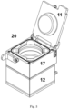
- FIG 3 an example of solvent recovery system (20) is shown, showing cooling unit (12), and evaporation unit (17), comprising closeable lid (11) through which a container can be inserted into the system.
- Evaporation unit (17) comprises heatable surface (2), and is configured to hold open container (3).
- Evaporation chamber (1) forms a fluid connection between evaporation unit (17) and cooling unit (12).
- Coolable surface (6) slopes downwards to outlet (9).
- Other internal surfaces (10) of evaporation chamber (1) such as the internal sidewalls and the inside surface of closeable lid (11) may also be heatable, such that unwanted condensation of solvent on these surfaces can be prevented.
- Coolable surface (6) is in heat exchanging contact with cooling fluid chamber (13) having an inlet (14) for introducing and an outlet (not shown) for removing for cooling fluid.
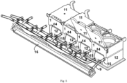
- FIG. 5 shows a modular solvent recovery system comprising four evaporation units (17) and four cooling units (12).
- Each cooling unit has an inlet (14) and an outlet (15) for introducing and removing cooling fluid.
- the inlets (14) and the outlets (15), respectively, may be connected with each other in parallel or in series.
- the outlets (9) for collecting condensed solvent of each of the chambers may also be connected in parallel. Condensed solvent can be collected in cold trap (16).
Landscapes
- Chemical & Material Sciences (AREA)
- Chemical Kinetics & Catalysis (AREA)
- Vaporization, Distillation, Condensation, Sublimation, And Cold Traps (AREA)
Priority Applications (2)
| Application Number | Priority Date | Filing Date | Title |
|---|---|---|---|
| EP23197202.7A EP4523773A1 (de) | 2023-09-13 | 2023-09-13 | Lösungsmittelrückgewinnungssystem |
| PCT/NL2024/050504 WO2025058521A1 (en) | 2023-09-13 | 2024-09-13 | Solvent recovery system |
Applications Claiming Priority (1)
| Application Number | Priority Date | Filing Date | Title |
|---|---|---|---|
| EP23197202.7A EP4523773A1 (de) | 2023-09-13 | 2023-09-13 | Lösungsmittelrückgewinnungssystem |
Publications (1)
| Publication Number | Publication Date |
|---|---|
| EP4523773A1 true EP4523773A1 (de) | 2025-03-19 |
Family
ID=88020953
Family Applications (1)
| Application Number | Title | Priority Date | Filing Date |
|---|---|---|---|
| EP23197202.7A Withdrawn EP4523773A1 (de) | 2023-09-13 | 2023-09-13 | Lösungsmittelrückgewinnungssystem |
Country Status (2)
| Country | Link |
|---|---|
| EP (1) | EP4523773A1 (de) |
| WO (1) | WO2025058521A1 (de) |
Citations (6)
| Publication number | Priority date | Publication date | Assignee | Title |
|---|---|---|---|---|
| JPS562881A (en) * | 1979-06-21 | 1981-01-13 | Shigeo Baba | Solvent recovery apparatus |
| DE3239341A1 (de) * | 1981-11-07 | 1983-05-19 | Leybold-Heraeus GmbH, 5000 Köln | Destillations- und sublimationsvorrichtung mit einem kondensator |
| EP0269190A2 (de) * | 1986-11-26 | 1988-06-01 | Siva International, Inc. | Dampfkühlfallen-Kontrollvorrichtung |
| WO2013039098A1 (ja) * | 2011-09-16 | 2013-03-21 | Hishida Iwao | 空気中より水を得る方法及び装置 |
| EP4008418A1 (de) * | 2019-09-10 | 2022-06-08 | Beijing Normal University | Rotationsverdampfer zur genauen und quantitativen rückgewinnung mehrerer lösungsmittel oder konzentrierung mehrerer proben gleichzeitig |
| US20220387904A1 (en) * | 2020-05-22 | 2022-12-08 | Agustus Berman Shelander | Short path distillation head |
-
2023
- 2023-09-13 EP EP23197202.7A patent/EP4523773A1/de not_active Withdrawn
-
2024
- 2024-09-13 WO PCT/NL2024/050504 patent/WO2025058521A1/en active Pending
Patent Citations (6)
| Publication number | Priority date | Publication date | Assignee | Title |
|---|---|---|---|---|
| JPS562881A (en) * | 1979-06-21 | 1981-01-13 | Shigeo Baba | Solvent recovery apparatus |
| DE3239341A1 (de) * | 1981-11-07 | 1983-05-19 | Leybold-Heraeus GmbH, 5000 Köln | Destillations- und sublimationsvorrichtung mit einem kondensator |
| EP0269190A2 (de) * | 1986-11-26 | 1988-06-01 | Siva International, Inc. | Dampfkühlfallen-Kontrollvorrichtung |
| WO2013039098A1 (ja) * | 2011-09-16 | 2013-03-21 | Hishida Iwao | 空気中より水を得る方法及び装置 |
| EP4008418A1 (de) * | 2019-09-10 | 2022-06-08 | Beijing Normal University | Rotationsverdampfer zur genauen und quantitativen rückgewinnung mehrerer lösungsmittel oder konzentrierung mehrerer proben gleichzeitig |
| US20220387904A1 (en) * | 2020-05-22 | 2022-12-08 | Agustus Berman Shelander | Short path distillation head |
Also Published As
| Publication number | Publication date |
|---|---|
| WO2025058521A1 (en) | 2025-03-20 |
Similar Documents
| Publication | Publication Date | Title |
|---|---|---|
| US12072149B2 (en) | Extraction freeze drying system with removable condenser | |
| US9242189B2 (en) | Continuous extractor, concentrator and dryer | |
| EP2601466B1 (de) | Gefriertrocknung von schüttgut mit sprühtrocknung und gerührter trocknung | |
| US9574799B2 (en) | Extractor and concentrator | |
| US10053648B2 (en) | Continuous-flow extraction system and method | |
| CA2027474A1 (fr) | Procede et dispositifs de decontamination de produits solides | |
| JP6561179B2 (ja) | 分散的通電抽出を使用した解析的分析のための迅速な試料調製 | |
| US4465554A (en) | Hot jet evaporator | |
| US20140190245A1 (en) | Reduced pressure liquid sampling | |
| WO2013192038A1 (en) | Convertible refrigerant recovery, recycle, and recharge system | |
| US9611521B2 (en) | Extraction of gallium and/or arsenic from gallium arsenide | |
| US8246905B2 (en) | Method for disinfecting a microtome cryostat | |
| WO2025058521A1 (en) | Solvent recovery system | |
| US5025571A (en) | Vacuum pump with heated vapor pre-trap | |
| JP4064349B2 (ja) | サンプルの固体支持体から液体中への移動 | |
| US11819800B2 (en) | Method and system for recovering and purifying a gaseous sterilizing agent | |
| JP7587313B2 (ja) | Gcms分析前の試料調製を改善するためのマトリックス加速真空支援収着剤抽出のシステム及び方法 | |
| CN212275401U (zh) | 一种样品浓缩装置 | |
| RU2222366C2 (ru) | Выпарной аппарат | |
| JP2901866B2 (ja) | 真空蒸留回収装置 | |
| EP3241010B1 (de) | Verfahren zur innenraumluftanalyse und probenahmeanordnung | |
| CN215757159U (zh) | 危废真空干化碳化设备 | |
| US20020148717A1 (en) | Device for evaporation and condensation in confined environment | |
| JP2002257698A (ja) | 液体試料の濃縮方法 | |
| JPH07198564A (ja) | 燃焼反応生成物採取装置 |
Legal Events
| Date | Code | Title | Description |
|---|---|---|---|
| PUAI | Public reference made under article 153(3) epc to a published international application that has entered the european phase |
Free format text: ORIGINAL CODE: 0009012 |
|
| STAA | Information on the status of an ep patent application or granted ep patent |
Free format text: STATUS: THE APPLICATION HAS BEEN PUBLISHED |
|
| AK | Designated contracting states |
Kind code of ref document: A1 Designated state(s): AL AT BE BG CH CY CZ DE DK EE ES FI FR GB GR HR HU IE IS IT LI LT LU LV MC ME MK MT NL NO PL PT RO RS SE SI SK SM TR |
|
| STAA | Information on the status of an ep patent application or granted ep patent |
Free format text: STATUS: THE APPLICATION IS DEEMED TO BE WITHDRAWN |
|
| 18D | Application deemed to be withdrawn |
Effective date: 20250920 |