EP4523788A1 - Procédé d'équipement ciblé d'une zone partielle d'un corps d'écoulement pourvu de métal noble et corps d'écoulement équipé d'une pièce de métal noble - Google Patents
Procédé d'équipement ciblé d'une zone partielle d'un corps d'écoulement pourvu de métal noble et corps d'écoulement équipé d'une pièce de métal noble Download PDFInfo
- Publication number
- EP4523788A1 EP4523788A1 EP23197582.2A EP23197582A EP4523788A1 EP 4523788 A1 EP4523788 A1 EP 4523788A1 EP 23197582 A EP23197582 A EP 23197582A EP 4523788 A1 EP4523788 A1 EP 4523788A1
- Authority
- EP
- European Patent Office
- Prior art keywords
- flow
- precious metal
- composition
- piece
- partial
- Prior art date
- Legal status (The legal status is an assumption and is not a legal conclusion. Google has not performed a legal analysis and makes no representation as to the accuracy of the status listed.)
- Pending
Links
Images



Classifications
-
- B—PERFORMING OPERATIONS; TRANSPORTING
- B01—PHYSICAL OR CHEMICAL PROCESSES OR APPARATUS IN GENERAL
- B01J—CHEMICAL OR PHYSICAL PROCESSES, e.g. CATALYSIS OR COLLOID CHEMISTRY; THEIR RELEVANT APPARATUS
- B01J23/00—Catalysts comprising metals or metal oxides or hydroxides, not provided for in group B01J21/00
- B01J23/38—Catalysts comprising metals or metal oxides or hydroxides, not provided for in group B01J21/00 of noble metals
- B01J23/40—Catalysts comprising metals or metal oxides or hydroxides, not provided for in group B01J21/00 of noble metals of the platinum group metals
- B01J23/42—Platinum
-
- B—PERFORMING OPERATIONS; TRANSPORTING
- B01—PHYSICAL OR CHEMICAL PROCESSES OR APPARATUS IN GENERAL
- B01J—CHEMICAL OR PHYSICAL PROCESSES, e.g. CATALYSIS OR COLLOID CHEMISTRY; THEIR RELEVANT APPARATUS
- B01J23/00—Catalysts comprising metals or metal oxides or hydroxides, not provided for in group B01J21/00
- B01J23/38—Catalysts comprising metals or metal oxides or hydroxides, not provided for in group B01J21/00 of noble metals
- B01J23/40—Catalysts comprising metals or metal oxides or hydroxides, not provided for in group B01J21/00 of noble metals of the platinum group metals
- B01J23/44—Palladium
-
- B—PERFORMING OPERATIONS; TRANSPORTING
- B01—PHYSICAL OR CHEMICAL PROCESSES OR APPARATUS IN GENERAL
- B01J—CHEMICAL OR PHYSICAL PROCESSES, e.g. CATALYSIS OR COLLOID CHEMISTRY; THEIR RELEVANT APPARATUS
- B01J35/00—Catalysts, in general, characterised by their form or physical properties
- B01J35/30—Catalysts, in general, characterised by their form or physical properties characterised by their physical properties
- B01J35/396—Distribution of the active metal ingredient
-
- B—PERFORMING OPERATIONS; TRANSPORTING
- B01—PHYSICAL OR CHEMICAL PROCESSES OR APPARATUS IN GENERAL
- B01J—CHEMICAL OR PHYSICAL PROCESSES, e.g. CATALYSIS OR COLLOID CHEMISTRY; THEIR RELEVANT APPARATUS
- B01J35/00—Catalysts, in general, characterised by their form or physical properties
- B01J35/50—Catalysts, in general, characterised by their form or physical properties characterised by their shape or configuration
- B01J35/56—Foraminous structures having flow-through passages or channels, e.g. grids or three-dimensional [3D] monoliths
-
- B—PERFORMING OPERATIONS; TRANSPORTING
- B01—PHYSICAL OR CHEMICAL PROCESSES OR APPARATUS IN GENERAL
- B01J—CHEMICAL OR PHYSICAL PROCESSES, e.g. CATALYSIS OR COLLOID CHEMISTRY; THEIR RELEVANT APPARATUS
- B01J37/00—Processes, in general, for preparing catalysts; Processes, in general, for activation of catalysts
- B01J37/02—Impregnation, coating or precipitation
- B01J37/0215—Coating
-
- F—MECHANICAL ENGINEERING; LIGHTING; HEATING; WEAPONS; BLASTING
- F01—MACHINES OR ENGINES IN GENERAL; ENGINE PLANTS IN GENERAL; STEAM ENGINES
- F01N—GAS-FLOW SILENCERS OR EXHAUST APPARATUS FOR MACHINES OR ENGINES IN GENERAL; GAS-FLOW SILENCERS OR EXHAUST APPARATUS FOR INTERNAL-COMBUSTION ENGINES
- F01N3/00—Exhaust or silencing apparatus having means for purifying, rendering innocuous, or otherwise treating exhaust
- F01N3/08—Exhaust or silencing apparatus having means for purifying, rendering innocuous, or otherwise treating exhaust for rendering innocuous
- F01N3/10—Exhaust or silencing apparatus having means for purifying, rendering innocuous, or otherwise treating exhaust for rendering innocuous by thermal or catalytic conversion of noxious components of exhaust
- F01N3/24—Exhaust or silencing apparatus having means for purifying, rendering innocuous, or otherwise treating exhaust for rendering innocuous by thermal or catalytic conversion of noxious components of exhaust characterised by constructional aspects of converting apparatus
- F01N3/28—Construction of catalytic reactors
- F01N3/2803—Construction of catalytic reactors characterised by structure, by material or by manufacturing of catalyst support
-
- F—MECHANICAL ENGINEERING; LIGHTING; HEATING; WEAPONS; BLASTING
- F01—MACHINES OR ENGINES IN GENERAL; ENGINE PLANTS IN GENERAL; STEAM ENGINES
- F01N—GAS-FLOW SILENCERS OR EXHAUST APPARATUS FOR MACHINES OR ENGINES IN GENERAL; GAS-FLOW SILENCERS OR EXHAUST APPARATUS FOR INTERNAL-COMBUSTION ENGINES
- F01N3/00—Exhaust or silencing apparatus having means for purifying, rendering innocuous, or otherwise treating exhaust
- F01N3/08—Exhaust or silencing apparatus having means for purifying, rendering innocuous, or otherwise treating exhaust for rendering innocuous
- F01N3/10—Exhaust or silencing apparatus having means for purifying, rendering innocuous, or otherwise treating exhaust for rendering innocuous by thermal or catalytic conversion of noxious components of exhaust
- F01N3/24—Exhaust or silencing apparatus having means for purifying, rendering innocuous, or otherwise treating exhaust for rendering innocuous by thermal or catalytic conversion of noxious components of exhaust characterised by constructional aspects of converting apparatus
- F01N3/28—Construction of catalytic reactors
- F01N3/2803—Construction of catalytic reactors characterised by structure, by material or by manufacturing of catalyst support
- F01N3/2835—Construction of catalytic reactors characterised by structure, by material or by manufacturing of catalyst support fibrous
-
- F—MECHANICAL ENGINEERING; LIGHTING; HEATING; WEAPONS; BLASTING
- F01—MACHINES OR ENGINES IN GENERAL; ENGINE PLANTS IN GENERAL; STEAM ENGINES
- F01N—GAS-FLOW SILENCERS OR EXHAUST APPARATUS FOR MACHINES OR ENGINES IN GENERAL; GAS-FLOW SILENCERS OR EXHAUST APPARATUS FOR INTERNAL-COMBUSTION ENGINES
- F01N2330/00—Structure of catalyst support or particle filter
- F01N2330/10—Fibrous material, e.g. mineral or metallic wool
-
- F—MECHANICAL ENGINEERING; LIGHTING; HEATING; WEAPONS; BLASTING
- F01—MACHINES OR ENGINES IN GENERAL; ENGINE PLANTS IN GENERAL; STEAM ENGINES
- F01N—GAS-FLOW SILENCERS OR EXHAUST APPARATUS FOR MACHINES OR ENGINES IN GENERAL; GAS-FLOW SILENCERS OR EXHAUST APPARATUS FOR INTERNAL-COMBUSTION ENGINES
- F01N2370/00—Selection of materials for exhaust purification
- F01N2370/02—Selection of materials for exhaust purification used in catalytic reactors
Definitions
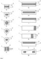
- the present invention relates to a method for equipping a flow-through body with at least one precious metal, wherein only a partial region A of the flow-through body is equipped with the at least one precious metal.
- the method comprises non-immersive coating with a composition containing a precious metal component and a solvent, wherein initially the entire amount of the applied composition remains on the partial region A of the flow-through body.
- the invention also relates to a one-piece flow-through body with at least one partial region A equipped with at least one precious metal, wherein the at least one partial region A is at least partially enclosed by one or more further partial regions B of the flow-through body.
- the invention relates to a catalytic converter comprising a one-piece flow-through body according to the invention or a flow-through body equipped according to the invention, an exhaust silencer comprising such a one-piece flow-through body or a flow-through body equipped according to the invention, and a method for exhaust gas aftertreatment using such a one-piece flow-through body or a flow-through body equipped according to the invention.
- Flow-through bodies for example in the form of wire bodies, are used in catalysts where a large surface area is crucial for bringing a material to be treated into contact with a catalytically active component.
- Such catalysts are typically used in the purification of exhaust gases, for example, from combustion engines.
- JP 2009156158 A proposes using such flow bodies as catalysts in silencers.
- Flow-through bodies are usually coated using so-called washcoat processes, for example in the CN 104588036 A
- the flow-through body to be coated is brought into contact, in whole or in part, with a suspension containing a solvent, at least one carrier component, and optionally a precious metal component, for example by immersion or suction processes.
- a precious metal-free washcoat suspension is applied first, the precious metal is coated in a further process step, in which a precious metal-containing solution is applied to the pre-coated flow-through body.
- the suspension or precious metal-containing solution is used in excess, meaning more solution volume is required than would be necessary to wet the surface of the flow-through body to be coated. In both cases, this leads to higher costs for the precious metal used in the manufacturing process.
- the object of the present invention is to provide a method for producing a body equipped with at least one precious metal, which allows for the precise placement of the catalytically active components and minimizes the precious metal inventory of the flow-through body. Furthermore, it is an object to reduce the amount of precious metal used during the manufacturing process.
- the method according to the invention thus makes it possible to produce a flow-through body having at least two subregions (hereinafter referred to as subregion A and subregion B), wherein at least one of the subregions is provided with at least one precious metal.
- the further subregion or subregions (subregion B) can be provided with no precious metal component, a different precious metal component, or fewer precious metal components.
- Such flow-through bodies are typically used in catalysts, wherein the precious metal acts as a catalytically active species.
- the method according to the invention is particularly advantageous because it allows the selective design of flow-through bodies. Furthermore, the targeted and partial application of the precious metal-containing composition makes it possible to minimize the amount of composition required. This allows the amount of precious metal component to be used to be reduced compared to processes in which an excess of composition is used. This advantage is particularly evident compared to immersive processes, in particular dipping processes. Furthermore, by using a suitable composition, a three-dimensional partial area of the flow-through body can be selectively equipped, in contrast to coating processes that are intended for the layer-by-layer build-up of coatings. A further advantage lies in the simple implementation of the method according to the invention, which does not require any additional aids such as masks or covers to coat specific partial areas.
- a flow-through body is partially equipped with precious metal.
- a flow-through body is understood to be a body through which gas can flow and which has a continuous network of channels and/or pores.
- the flow-through body can be designed as a porous matrix with a plurality of Irregularly or regularly shaped passages can be described.
- Flow-through bodies are characterized by a large surface area per total volume.
- the flow-through body is a one-piece body.
- the flow-through body is dimensionally stable.
- the shape of the flow body is not further restricted.
- the flow body can be designed, for example, in the form of a cube, a cuboid, a sphere, a pyramid, a cone, or a cylinder.
- the flow-through body has at least one end face, preferably exactly two end faces, such as in the case of a cylinder or cuboid.
- the flow-through body has a circumferential surface extending from the at least one end face; in the case of a cuboid or cylinder, the circumferential surface extends from the first end face to the second end face.
- the at least one end face and the circumferential surface form the edge regions of the flow-through body, or more precisely, they form the surfaces of the edge regions of the flow-through body.
- the geometry of the flow body is determined by a central longitudinal axis and a perpendicular transverse axis.
- the longitudinal axis is longer than the transverse axis, as in a cuboid or cylinder. In these cases, the longitudinal axis extends from the first to the second end face.
- the total volume of the flow-through body can be, for example, 10 cm 3 to 200 cm 3 , in particular 20 cm 3 to 100 cm 3 .
- the density of the flow-through body is advantageously 0.6 g/cm 3 to 2 g/cm 3 , in particular 0.9 g/cm 3 to 1.7 g/cm 3 .
- the flow-through body typically comprises a ceramic material or a metallic material.
- the flow-through body may comprise cordierite (SiO 2 -Al 2 O 3 -MgO), silicon carbide (SiC), titanium, an iron alloy such as an Fe-Cr-Al alloy or a heat-resistant steel, in particular 1.4767, or a nickel alloy such as a Ni-Cr alloy, a Ni-Cr-Al alloy, or a Ni-Cr-Fe alloy, in particular 2.4851.
- the flow-through body can be a foam, a body consisting of irregularly arranged fibers, a body made of expanded metal, or a wire body.
- Flow-through bodies in the form of a wire body are particularly preferred.
- a wire body is understood to be a body formed from one or more wires.
- a wire body formed from more than one wire can also be a one-piece flow-through body.
- a wire is a thin, elongated, flexible metal part.
- the wire preferably has a round cross-section.
- a square cross-section can also be advantageous.
- the cross-section of the wire is advantageously constant over its length within the scope of usual manufacturing tolerances.
- the wire body may be a knitted wire mesh, a wire cloth, a shaped metal wire, a wire mat or a wound wire mat.
- the diameter of the wire of the wire body or, in the case of a non-circular cross-section, the greatest extension of the wire in cross-section is advantageously from 0.1 mm to 2 mm, in particular from 0.2 mm to 1 mm. A diameter of 0.3 mm to 1 mm is considered particularly advantageous.
- the wire diameter is particularly preferably at most 0.5 mm.
- the present invention relates to a method for equipping the flow-through body with at least one precious metal.
- a precious metal is understood to be a metal selected from the group consisting of platinum group metals, gold, and silver.
- Platinum group metals are understood to be the metals of the so-called platinum group, i.e., platinum (Pt), palladium (Pd), iridium (Ir), rhodium (Rh), osmium (Os), and ruthenium (Ru).
- metal metal
- precious metal or, for example, platinum
- platinum can exist in elemental form, i.e., in oxidation state 0, or in a higher oxidation state.
- Precious metals often exhibit catalytic activity for certain reactions, for example, the decomposition of exhaust gas components.
- the at least one precious metal therefore represents a catalytically active component of an appropriately equipped flow body.
- the at least one precious metal is preferably selected from the group consisting of platinum (Pt), palladium (Pd), iridium (Ir), rhodium (Rh), ruthenium (Ru) and combinations thereof, in particular the at least one precious metal is platinum, palladium, rhodium, a combination of platinum and rhodium or a combination of platinum, palladium and rhodium.
- a composition containing a noble metal component and a solvent is provided.
- the noble metal component is a component of the at least one noble metal with which the partial region of the flow-through body is to be provided.
- a "noble metal component” is understood to mean a component that consists at least partially of at least one noble metal.
- the noble metal component can be a precursor component of a catalytically active species, for example in the form of a corresponding noble metal compound. Suitable noble metal compounds are complexes, organometallic compounds, or salts of the noble metal, for example nitrates, halides, acetylacetonates, or acetates, but also a variety of other salts known to the person skilled in the art.
- the noble metal component can also already be present in the form of a catalytically active species.
- the noble metal component can also be at least partially metallic noble metal, for example in the form of particles, in particular in the form of nanoparticles.
- the composition may also contain multiple precious metal components. In this case, these may be multiple components of the same precious metal or different precious metals.
- the at least one precious metal component is a component of a precious metal selected from the group consisting of platinum (Pt), palladium (Pd), iridium (Ir), rhodium (Rh), ruthenium (Ru), and, in the case of multiple precious metal components, combinations thereof.
- platinum, palladium, or rhodium are particularly preferred, for example, platinum and palladium, platinum and rhodium, or platinum, palladium, and rhodium.
- the amount of the noble metal component of the at least one noble metal in the composition can vary within wide ranges and is determined by the intended loading of the flow-through body with the at least one noble metal. In particular, the amount of the at least one noble metal is determined by the intended loading.
- the "amount of the at least one noble metal” refers to the proportion of the at least one noble metal in the composition and not necessarily to the amount of the noble metal component. In the case where the noble metal component is a noble metal compound, this does not refer to the amount of the noble metal compound, but rather to the amount of the noble metal in the noble metal compound.
- the composition preferably comprises 0.5 to 90 wt.% of the at least one noble metal, based on the total weight of the composition comprising the at least one solvent and the at least one noble metal component.
- the composition comprises 1 to 80 wt.% of the at least one noble metal, preferably 5 to 70 wt.%. Particularly good results are obtained when the composition contains the at least one precious metal in an amount of at least 0.5 wt.%, in particular at least 1 wt.%, preferably at least 5 wt.%, preferably at least 10 wt.%.
- the noble metal component can be an Ir(IV) compound, e.g., an Ir(IV) salt, an Ir(IV) complex, or an Ir organometallic compound.
- Ir(IV) compound e.g., an Ir(IV) salt, an Ir(IV) complex, or an Ir organometallic compound.
- suitable iridium compounds are iridium chloride, iridium acetate, iridium acetylacetonate, iridium sulfate, and dihydrogen hexachloroiridate.
- the precious metal component may be a platinum(II) or a platinum(IV) compound, e.g. a Pt(II) or Pt(IV) salt, a Pt(II) or Pt(IV) complex compound, or a Pt(II) or Pt(IV) organometallic compound.
- a platinum(II) or a platinum(IV) compound e.g. a Pt(II) or Pt(IV) salt, a Pt(II) or Pt(IV) complex compound, or a Pt(II) or Pt(IV) organometallic compound.
- platinum compounds include platinum halides, such as platinum(II) chloride or platinum(IV) chloride or an acid thereof, hexachloroplatinic acid or a salt of this acid, platinic acid or a salt of this acid, hydroxyethylammonium hexahydroxoplatinate, ammonium hexachloroplatinate, ammonium tetrachloroplatinate, potassium tetrachloroplatinate, potassium hexachloroplatinate, sodium tetrachloroplatinate, potassium tetrahydroxyplatinate, platinum nitrate, platinum sulfite, platinum ethanolamine, platinum acetylacetonate, platinum oxalate, or a mixture of at least two of these compounds.
- platinum halides such as platinum(II) chloride or platinum(IV) chloride or an acid thereof, hexachloroplatinic acid or a salt of this acid, platinic acid or a salt of this
- the noble metal component may be a palladium(II) or a palladium(IV) compound, e.g. a Pd(II) or Pd(IV) salt, a Pd(II) or Pd(IV) complex compound or a Pd(II) or Pd(IV) organometallic compound.
- a palladium(II) or a palladium(IV) compound e.g. a Pd(II) or Pd(IV) salt, a Pd(II) or Pd(IV) complex compound or a Pd(II) or Pd(IV) organometallic compound.
- palladium halides such as palladium(II) chloride, palladium(II) bromide or palladium(IV) chloride or an acid thereof, palladium acetate, palladium nitrate, palladium acetylacetonate, palladium sulfate, palladium oxalate, hydroxyethylammonium hexahydroxopalladate, ammonium hexachloropalladate, ammonium tetrachloropalladate, potassium tetrachloropalladate, potassium hexachloropalladate, sodium tetrachloropalladate, potassium tetrahydroxypalladate, diaminedichloropalladium, tetraaminepalladium nitrate, tetraaminepalladium chloride, tetraaminepalladium hydroxide, tetraaminepalladium sulfate or a mixture of at least two
- the noble metal component can be a ruthenium(III) or a ruthenium(IV) compound, e.g., Ru(III) or Ru(IV) salts, Ru(III) or Ru(IV) complex compounds, or Ru(III) or Ru(IV) organometallic compounds.
- ruthenium compounds include nitrates, acetylacetonates or acetates, and halides.
- Suitable ruthenium compounds include ruthenium nitrate, ruthenium acetate, ruthenium pentacarbonyl, ruthenium acetylacetonate, ruthenium oxalate, ruthenocene, and ruthenium nitrosyl nitrate, or a mixture of at least two of these compounds.
- the noble metal component may be a Rh(III) compound, e.g., a Rh(III) salt, a Rh(III) complex, or a Rh organometallic compound.
- suitable rhodium compounds are rhodium halides, such as rhodium(III) chloride, or an acid thereof, rhodium nitrate, rhodium acetylacetonate, rhodium sulfate, or a mixture of at least two of these compounds.
- the composition contains a solvent.
- the solvent is preferably an aqueous solvent, acetone, or an alcohol; advantageously, the solvent comprises water. It has been found to be advantageous if the solvent consists primarily of water; in particular, the solvent comprises at least 70% by weight of water. more preferably at least 80% by weight, particularly preferably at least 90% by weight water. It may also be advantageous if the solvent comprises only water, i.e., consists entirely of water.
- the composition is preferably a non-solid composition.
- the composition can be liquid or viscous, for example in the form of a solution, an emulsion, a suspension, a dispersion, or a paste.
- a suspension within the meaning of the present invention is a mixture of a solid and a liquid, wherein the solid is present in the form of finely divided solids uniformly distributed in the liquid.
- the composition exhibits thixotropic properties.
- thixotropic properties are said to exist when a fluid exhibits a lower viscosity under constant and sustained force (shear stress phase) than under static conditions, and the static viscosity returns as soon as the force is removed (complete recovery of viscosity in the rest phase).
- the composition has a static viscosity of at least 500 mPa*s, more preferably at least 1000 mPa*s, in particular at least 20,000 mPa*s.
- Suitable compositions have, for example, a static viscosity in the range of 500 to 100,000 mPa*s, preferably in the range of 1000 to 50,000 mPa*s, particularly preferably in the range of 2000 to 30,000 mPa*s.
- the static viscosity of a composition can be determined according to a measurement described later. The determination of static viscosity is also known to those skilled in the art as a CS measurement ( controlled stress ).
- the composition has a dynamic viscosity of not more than 2500 mPa*s, more preferably not more than 1500 mPa*s, in particular not more than 1000 mPa*s.
- a composition with a minimum dynamic viscosity it can be ensured that the composition can be applied specifically to the flow-through body.
- Suitable compositions have, for example, a dynamic viscosity in the range of 50 to 2500 mPa*s, preferably in the range of 100 to 1500 mPa*s, particularly preferably in the range of 200 to 1000 mPa*s.
- the determination of the dynamic viscosity of a composition can be carried out according to a measurement described later.
- the determination of the dynamic Viscosity is also known to those skilled in the art as CR measurement (constant shear rate, controlled rate ).
- the composition has a thixotropy index TI of at least 5, in particular at least 10, and particularly preferably at least 20.
- the thixotropy index TI is understood to be the ratio of static to dynamic viscosity.
- the viscosity of the composition can be specifically adjusted using methods known to those skilled in the art.
- the composition preferably contains a thickener, for example a polyvinyl alcohol, an oxide and/or hydroxide of aluminum such as boehmite, a nitrate of cerium, aluminum or zirconium, or a hydrocolloid.
- a hydrocolloid to be a substance that can dissolve in water as a colloid and exhibits a high gel-forming capacity.
- Hydrocolloids are typically polymers, in particular proteins or polysaccharides, obtained from natural sources such as plants, algae, or animals.
- the hydrocolloid can be, for example, a cellulose, in particular a methylcellulose or a hydroxycellulose, a pectin, an alginate, gelatin, agar, or carrageenan.
- the composition preferably contains at least 0.5% by weight of the thickener, based on the total weight of the composition, in particular at least 1.5% by weight, particularly preferably at least 2% by weight.
- the composition preferably contains less than 10% by weight of the thickener, in particular less than 8% by weight, particularly preferably less than 5% by weight. If the proportion of thickener is greater, the viscosity of the composition is too high to be able to use it according to the invention. It has proven advantageous if the composition contains the thickener in a range from 0.5 to 10% by weight, in particular in a range from 2 to 8% by weight.
- the composition may be a washcoat suspension.
- washcoat is familiar to those skilled in the art. A distinction must be made between a washcoat suspension and a washcoat layer that can be applied or has been applied to a macroscopic substrate, such as a flow-through body.
- washcoat suspensions are used to coat catalyst supports with a washcoat layer.
- the flow-through bodies coated with the process according to the invention are such catalyst supports.
- the washcoat suspension preferably contains at least one microscopic support, typically an oxidic support material.
- the microscopic support is to be distinguished from the macroscopic support, in the case of the present invention, from the flow-through body to be coated.
- the oxidic support material may comprise a refractory oxide, preferably selected from the group consisting of aluminum oxide, magnesium oxide, silicon oxide, molybdenum oxide, tungsten oxide, titanium oxide, their mixed oxides, and composite oxides of two or more thereof.
- the refractory oxide may be doped; in other words, the refractory oxide may contain a dopant.
- Refractory oxides doped with a dopant are obtainable using methods known in the relevant art. Suitable dopants may be selected from the group consisting of rare earth metals, transition metals, alkaline earth metals, and mixtures thereof.
- the dopant can be at least one element selected from the group consisting of cerium (Ce), zirconium (Zr), titanium (Ti), silicon (Si), manganese (Mn), yttrium (Y), lanthanum (La), barium (Ba), praseodymium (Pr), gadolinium (Gd), samarium (Sm), neodymium (Nd), and their oxides.
- the dopant preferably comprises La, Ba, Sr, Zr, or Mn.
- the refractory oxide is an aluminum oxide doped with lanthanum or lanthanum oxide, a mixed oxide of aluminum oxide doped with lanthanum or lanthanum oxide, or a composite oxide of aluminum oxide doped with lanthanum or lanthanum oxide.
- the washcoat suspension preferably comprises the oxidic carrier material in a proportion of 5 to 50 wt.%, particularly preferably in a proportion of 10 to 40 wt.%, based on the total weight of the washcoat suspension.
- the oxidic support material may also comprise an oxygen storage component, preferably a cerium oxide and/or a cerium-zirconium oxide.
- the cerium-zirconium oxide may be a mixed oxide or a mixture of cerium oxide (CeO2) and zirconium oxide (ZrO2).
- the oxidic support material may comprise a refractory oxide and an oxygen storage component.
- a cerium-zirconium oxide it can be either a cerium-rich oxide or a zirconium-rich oxide.
- the cerium-zirconium oxide can preferably contain 10 to 50 wt.% zirconium oxide, preferably 15 to 40 wt.%, based on the total weight of the cerium-zirconium oxide.
- the cerium-zirconium oxide preferably contains cerium oxide in an amount of 20 to 90 wt.%, particularly preferably 40 to 85 wt.%, in each case based on the total weight of the cerium-zirconium oxide.
- the oxygen storage component can comprise at least one element other than cerium from the group of rare earths.
- the at least one element from the group of rare earths is preferably present as an oxide.
- the at least one rare earth element is selected from the group consisting of neodymium (Nd), praseodymium (Pr), lanthanum (La), and hafnium (Hf).
- the oxygen storage component can comprise, for example, a cerium-zirconium-lanthanum oxide, a cerium-zirconium-yttrium oxide, a cerium-zirconium-lanthanum-yttrium oxide, a cerium-zirconium-neodymium oxide, a cerium-zirconium-praseodymium oxide, a cerium-zirconium-lanthanum-neodymium oxide, a cerium-zirconium-praseodymium oxide, a cerium-zirconium-lanthanum-neodymium-praseodymium oxide, or a combination thereof.
- the proportion of the respective rare earth oxides can be 2 wt.% to 20 wt.%, preferably 5 wt.% to 15 wt.%, based on the total weight of the oxygen storage component.
- the washcoat suspension preferably comprises the oxygen storage component in a proportion of 5 to 50 wt.%, particularly preferably in a proportion of 10 to 40 wt.%, based on the total weight of the washcoat suspension.
- the oxidic support material has a large BET surface area; preferably, the BET surface area is at least 30 m 2 /g, in particular at least 80 m 2 /g, particularly preferably at least 100 m 2 /g. Typically, the BET surface area of the oxidic support material is between 30 and 300 m 2 /g, preferably between 50 and 200 m 2 /g.
- the BET surface area is also called the specific surface area and can be determined according to ISO 9277:2010 using nitrogen as the adsorbate.
- the precious metal component can be supported on an oxidic support material, in particular on a refractory oxide and/or an oxygen storage component.
- the oxidic support material is equipped with the at least one precious metal component, i.e., that the precious metal component is present on, in, or on the oxidic support material, for example in the form of an adsorbed precursor component, particles, or a layer.
- the equipment of the oxidic support material can be present both on the surface and inside the oxidic support material.
- the term "surface” here encompasses both the outer and inner surfaces; in other words, it also includes the internal surface formed by pores.
- the coating of an oxidic support material with the at least one precious metal component can be carried out by methods known to those skilled in the art, for example by impregnation, precipitation, chemical vapor deposition (CVD ), or spraying.
- the coating typically comprises combining the oxidic support material with at least one precious metal compound, which is usually provided in a preparation comprising at least one solvent.
- the precipitation and/or reduction of the at least one precious metal compound and a drying and/or calcination step can take place.
- the preparation can be absorbed into or in the oxidic support material by capillary forces, so that the volume of the preparation approximately corresponds to the pore volume of the oxidic support material, known to those skilled in the art as the "incipient wetness method.”
- the washcoat suspension may also contain the precious metal component in the form of an unsupported precious metal compound, in particular a precious metal precursor component.
- the composition may also contain additional components such as acids or bases for pH regulation, fillers, binders, pore formers, adhesion promoters, or stabilizers.
- additional components typically do not have catalytic activity, but rather improve the processability of the composition or the properties of the coating produced therefrom, for example, by increasing the operating temperature range, an increase in the contact surface, an improvement in the adhesion properties or similar.
- step (iii) the flow body is coated with the composition.
- Non-immersive coating is carried out by applying the composition to a partial area A of the flow-through body.
- the coating is carried out only selectively on at least one partial area A of the flow-through body, thereby achieving a partial coating of the flow-through body.
- the coating is carried out by applying a predefined amount of the composition to the partial area A to be coated.
- the coating is non-immersive, meaning that the coating is not applied by immersing the flow-through body into the composition.
- Coating techniques that rely on immersing the body to be coated do not allow for the intended selective and targeted application of the coating. Immersion processes are particularly unsuitable for partial areas A inside the flow-through body, i.e., those that are partially or completely enclosed by one or more partial areas B of the flow-through body.
- the non-immersive coating is advantageously carried out by a method selected from the group consisting of pipetting, brushing, stamping, spreading, injecting, rolling or printing.
- the volume of the coated partial area A is advantageously 5% to 90%, in particular 10% to 80%, of the total volume of the flow-through body. Particularly advantageously, the volume of partial area A is at most 60%, in particular at most 50%, of the total volume of the flow-through body. A volume of partial area A of 15% to 30% of the total volume of the flow-through body has proven particularly advantageous.
- the cross-sectional area of the partial region A provided with at least one precious metal perpendicular to the longitudinal axis of the flow-through body amounts to no more than 80% of the total cross-sectional area of the flow-through body perpendicular to the longitudinal axis in the direction of the longitudinal axis, in particular no more than 70%, preferably no more than 60%.
- the cross-sectional area of the partial region A perpendicular to the longitudinal axis amounts to more than 30% of the total cross-sectional area of the flow-through body perpendicular to the longitudinal axis in the direction of the longitudinal axis, preferably more than 40%.
- the partial region A provided with at least one precious metal can extend along the entire length of the longitudinal axis of the flow-through body.
- the length of the partial region A provided with at least one precious metal along the longitudinal axis of the flow-through body amounts to no more than 80% of the total length of the flow-through body along the longitudinal axis, in particular no more than 70%, preferably no more than 60%.
- the length of the partial region A along the longitudinal axis amounts to more than 30% of the total length of the flow-through body, preferably more than 40%.
- At least 50%, in particular at least 80%, of at least one of the end faces are not covered by the partial area A provided with at least one precious metal. formed.
- this at least one end face is not entirely formed by the partial region A provided with at least one precious metal.
- the partial region A provided with at least one precious metal does not border on at least one end face. The method is particularly advantageous if the partial region A provided with at least one precious metal does not border on any of the end faces of the flow-through body.
- non-immersive coating may also be carried out on a central partial region A of the flow-through body, which at least partially does not border any edge region.
- the method according to the invention is particularly advantageous for such embodiments, since such inner partial regions A of the flow-through body can be coated with precious metal in a targeted manner.
- the entire amount of the composition applied to sub-area A of the flow-through body initially remains on the flow-through body.
- the time limitation "initially” here means that the composition remains on sub-area A immediately after application, but can optionally be at least partially removed again in subsequent process steps.
- process step (iv) at least the volatile components of the composition, in particular the solvent, are removed.
- the total amount of the composition is understood to be the amount that reaches the partial area A of the flow body during application.
- the amount of composition applied and the amount that actually reaches the substrate to be coated are not identical. Such losses can be caused, for example, by evaporation of components of the composition, particularly the solvent.
- step (iv) the volatile components of the composition are removed from subregion A.
- Volatile components are those components that are evaporable under normal conditions.
- Non-volatile components of the composition in particular the precious metal component or parts of the precious metal component, remain on the subregion.
- the volatile components of the composition include, in particular, the solvent. Parts of the precious metal component may also be volatile.
- Removal may be carried out by methods known to those skilled in the art, such as passive drying, heating or removal under reduced pressure.
- the process according to the invention may also comprise further steps, for example a step for precipitating and/or fixing a noble metal precursor component, a drying step and/or a step for converting a noble metal precursor component into a catalytically active noble metal component.
- equipping the flow-through body with at least one precious metal includes a calcination step.
- calcination to mean a thermal treatment in which a metallic component is fixed to a support material.
- the calcination step is particularly advantageous when the temperature is in the range of 150 to 700°C, in particular 200 to 600°C. In preferred embodiments, the temperature is more than 200°C, particularly preferably more than 300°C.
- the drying step takes place over a period of 1 to 24 hours, preferably 2 to 12 hours.
- the loading of the flow-through body with the at least one precious metal is selected so that the precious metal configuration can be used as efficiently as possible.
- the loading with the at least one precious metal is preferably in the range of 0.01 to 1 g/L, particularly preferably in the range of 0.05 to 0.8 g/L, and especially preferably in the range of 0.01 to 0.7 g/L.
- the loading indicates the amount of the at least one precious metal relative to the volume of the entire flow-through body.
- the subregion A of the flow-through body is provided with precious metal in a range of 0.1 - 10 g/L, in particular in a range of 0.5 - 8 g/L.
- the subregion A of the flow-through body is provided with less than 8 g/L of the at least one precious metal, in particular with less than 5 g/L. In this case, the provision indicates the amount of the at least one precious metal relative to the volume of the subregion A.
- the process according to the invention can produce a flow-through body in which the catalytically active precious metal is used as efficiently as possible.
- the amount of precious metal can be reduced to maintain the same catalytic performance or the catalytic performance can be increased with the same amount of precious metal.
- the method according to the invention can also be carried out several times, for example in order to equip different partial areas of the flow-through body with different amounts of the at least one precious metal or in order to equip different partial areas with different precious metals.
- the flow-through body can initially be completely coated with a precious metal-free washcoat suspension, i.e., with a precious metal-free washcoat layer.
- a precious metal-free washcoat suspension i.e., with a precious metal-free washcoat layer.
- Preferred components of such a precious metal-free washcoat suspension are described above, which, with the exception of the information regarding the precious metal component, also apply here.
- the method according to the invention is carried out to selectively equip partial regions of the thus pretreated flow-through body with the at least one precious metal.
- the flow-through body comprises at least a first partial region equipped with a precious metal-free washcoat layer, i.e., one without a catalytically active component, and at least a second partial region equipped with a washcoat layer and at least one precious metal. Only this second partial region A thus has a catalytically active component.
- the flow-through body can initially be partially coated with a precious metal-free washcoat suspension, i.e., coated in partial areas with a precious metal-free washcoat layer.
- the method according to the invention is then carried out to selectively coat partial areas of the thus pretreated flow-through body with the at least one precious metal.
- the flow-through body comprises at least a first partial area that is neither coated with a washcoat coating nor with a precious metal, at least a second partial area that is coated only with a precious metal-free washcoat layer, and at least a third partial area that is coated with a washcoat layer and at least one precious metal. Only this third partial area therefore has a catalytically active component.
- parts of the flow body be coated neither with a washcoat nor with a precious metal.
- a combination of all variants is also possible.
- the invention also relates to a one-piece flow-through body with at least one partial region A provided with at least one precious metal, wherein the at least one partial region A is at least partially enclosed by one or more further partial regions B of the one-piece flow-through body.
- the flow-through body according to the invention is a one-piece flow-through body.
- the flow-through body is not composed of multiple individual bodies.
- the one-piece flow-through body can have multiple components; for example, in cases where it is a wire body, it can comprise multiple wires that form the one-piece flow-through body.
- the one-piece design of the flow-through body according to the invention is particularly advantageous because it allows for a minimization of components to provide a flow-through body with a subregion A enclosed by at least one further subregion B.
- the subregions A and B differ in particular in their precious metal configuration, such as the loading with precious metal, the type of precious metal, or the combination of several precious metals.
- the subregion or subregions B can, in particular, be precious metal-free.
- the shape of the one-piece flow body is not further restricted.
- the one-piece flow body can be designed, for example, in the form of a cube, a cuboid, a sphere, a pyramid, a cone, or a cylinder.
- the one-piece flow-through body has at least one end face, preferably exactly two end faces, such as in the case of a cylinder or cuboid.
- the one-piece flow-through body has a circumferential surface extending from the at least one end face; in the case of a cuboid or cylinder, the circumferential surface extends from the first end face to the second end face.
- the at least one The front side and the peripheral surface form the edge areas of the one-piece flow body.
- the geometry of the one-piece flow body is determined by a central longitudinal axis and a perpendicular transverse axis.
- the longitudinal axis is longer than the transverse axis, as in a cuboid or cylinder, for example. In these cases, the longitudinal axis extends from the first to the second end face.
- the total volume of the one-piece flow-through body can be, for example, 10 cm 3 to 200 cm 3 , in particular 20 cm 3 to 100 cm 3 .
- the density of the one-piece flow-through body is advantageously 0.6 g/cm 3 to 2 g/cm 3 , in particular 0.9 g/cm 3 to 1.7 g/cm 3 .
- the one-piece flow-through body typically comprises a ceramic material or a metallic material.
- the one-piece flow-through body can comprise cordierite (SiO 2 -Al 2 O 3 -MgO), silicon carbide (SiC), titanium, an iron alloy such as an Fe-Cr-Al alloy or a heat-resistant steel, in particular 1.4767, or a nickel alloy such as a Ni-Cr alloy, a Ni-Cr-Al alloy, or a Ni-Cr-Fe alloy, in particular 2.4851.
- the one-piece flow body can be a foam, a body consisting of irregularly arranged fibers, a body made of expanded metal or a metal sheet, or a wire body.
- Flow bodies in the form of a wire body are particularly preferred.
- the wire preferably has a round cross-section. A square cross-section can also be advantageous.
- the cross-section of the wire is constant along its length within the usual manufacturing tolerances.
- the wire body may be a knitted wire mesh, a knitted or woven wire mesh, a shaped metal wire, a wire mat or a wound wire mat.
- the diameter of the wire of the wire body or, in the case of a non-circular cross-section, the greatest extension of the wire in cross-section is advantageously from 0.1 mm to 2 mm, in particular from 0.2 mm to 1 mm. A diameter of 0.3 mm to 1 mm is considered particularly advantageous.
- the wire diameter is particularly preferably at most 0.5 mm.
- At least one partial region A of the one-piece flow-through body is provided with at least one precious metal.
- the at least one partial region A can be provided with the precious metal using various methods, in particular using the method according to the invention as described above.
- the at least one partial region A is at least partially enclosed by one or more further partial regions B of the one-piece flow-through body.
- the partial region A is at least partially arranged inside the one-piece flow-through body.
- the partial region A is completely enclosed by one or more further partial regions B; in other words, in such cases, the partial region A does not border any edge region of the one-piece flow-through body.
- the volume of the partial area A equipped with at least one precious metal is advantageously 5% to 90%, in particular 10% to 80% of the total volume of the one-piece flow-through body.
- the volume of partial area A is at most 60%, in particular at most 50% of the total volume of the one-piece flow-through body.
- a volume of partial area A of 15% to 30% of the total volume of the one-piece flow-through body has proven particularly advantageous.
- the shape of the partial area A equipped with at least one precious metal is not further restricted; in particular, the partial area A can be point-shaped, cylindrical, or spherical.
- both the one-piece flow body and the one with Partial region A containing at least one precious metal may be cylindrical, cuboid or disc-shaped.
- the cross-sectional area of the partial region A provided with at least one precious metal perpendicular to the longitudinal axis of the one-piece flow-through body amounts to no more than 80% of the total cross-sectional area of the one-piece flow-through body perpendicular to the longitudinal axis in the direction of the longitudinal axis, in particular no more than 70%, preferably no more than 60%.
- the cross-sectional area of the partial region A perpendicular to the longitudinal axis amounts to more than 30% of the total cross-sectional area of the one-piece flow-through body perpendicular to the longitudinal axis in the direction of the longitudinal axis, preferably more than 40%.
- the partial region A provided with at least one precious metal can extend along the entire length of the longitudinal axis of the one-piece flow-through body.
- the length of the partial region A provided with at least one precious metal along the longitudinal axis of the one-piece flow-through body amounts to no more than 80% of the total length of the one-piece flow-through body along the longitudinal axis, in particular no more than 70%, preferably no more than 60%.
- the length of the partial region A along the longitudinal axis amounts to more than 30% of the total length of the one-piece flow-through body, preferably more than 40%.
- At least 50% of the circumferential surface of the one-piece flow-through body is not formed by the partial area A provided with at least one precious metal, in particular at least 80%, particularly preferably the entire circumferential surface is not formed by the partial area A provided with at least one precious metal.
- At least 50%, in particular at least 80%, of at least one of the end faces is not formed by the partial region A provided with at least one precious metal.
- this at least one end face is not formed entirely by the partial region A provided with at least one precious metal.
- the partial region A provided with at least one precious metal does not adjoin at least one end face.
- the partial region A provided with at least one precious metal does not adjoin any of the end faces of the one-piece flow-through body.
- the loading of the one-piece flow-through body with precious metal is selected so that the precious metal equipment can be used as efficiently as possible.
- the loading with precious metal here refers to the entire loading of the one-piece flow-through body with precious metal, thus also including any precious metal loading of other sub-areas.
- the loading with precious metal is preferably in the range of 0.01 to 1 g/L, particularly preferably in the range of 0.05 to 0.8 g/L, and especially preferably in the range of 0.01 to 0.7 g/L.
- the loading indicates the amount of the at least one precious metal relative to the volume of the one-piece flow-through body.
- the partial region A of the one-piece flow-through body is provided with the at least one precious metal in a range of 0.1 - 10 g/L, in particular in a range of 0.5 - 8 g/L.
- the partial region A of the one-piece flow-through body is provided with less than 8 g/L of the at least one precious metal, in particular with less than 5 g/L.
- the provision indicates the amount of the at least one precious metal relative to the volume of the partial region A.
- the further subregion or subregions B of the one-piece flow-through body can have no coating or, for example, a washcoat coating.
- a washcoat coating Regarding advantageous compositions of the washcoat coating, reference is made to the above statements, which also apply to the coating of the one-piece flow-through body.
- the one-piece flow-through body can also have several subregions that are equipped with at least one precious metal.
- the several subregions can be equipped the same or differently and, in the case of different equipment, differ in the precious metal, the combination of precious metals, or the amount of precious metal or precious metals.
- the one-piece flow-through body can have subregions that are equipped with a precious metal-free washcoat layer.
- the one-piece flow-through body can have at least one first partial region or several partial regions which are provided with a precious metal-free washcoat layer and at least one second partial region which is provided with at least one precious metal.
- the invention further relates to a catalyst comprising a one-piece flow-through body according to the invention or a flow-through body equipped with at least one precious metal, produced according to the method according to the invention, and a catalyst housing.
- a catalyst comprising a one-piece flow-through body according to the invention or a flow-through body equipped with at least one precious metal, produced according to the method according to the invention, and a catalyst housing.
- the catalyst according to the invention can be used, for example, in small engines, in particular two-stroke engines, mixture-lubricated four-stroke engines or separately lubricated internal combustion engines, in particular for exhaust gas aftertreatment.
- the catalyst housing is made of steel, for example 1.4828, 1.4509 or 1.4767 steel.
- the catalyst housing advantageously has at least one inlet opening and at least one outlet opening.
- the housing has more inlet openings than outlet openings.
- the at least one inlet opening and the at least one outlet opening are preferably arranged on opposite end faces of the catalyst housing.
- the at least one inlet opening and the at least one outlet opening are advantageously arranged at least partially offset from one another.
- the at least one inlet opening and the at least one outlet opening do not overlap with one another.
- the overlap of the inlet opening and outlet opening refers to the inflow direction of an exhaust gas through the respective inlet opening, i.e. to a direction perpendicular to the surface of the at least one inlet opening.
- the flow body is preferably arranged so that, for example, exhaust gases to be treated can flow through the inlet opening into the catalyst housing, in Catalyst housing can flow through the flow body and then flow out through the outlet opening.
- the catalyst housing can be manufactured in one piece or consist of several parts, preferably two half-shells.
- the two-half-shell design allows for particularly simple production of the catalyst.
- the volume of the flow-through body is at least 80% of the volume enclosed by the catalyst housing, in particular at least 90%.
- the flow-through body completely fills the volume of the catalyst housing.
- the flow-through body has a circumferential surface that is advantageously in contact with the catalyst housing. It is particularly advantageous if at least 50% of the circumferential surface of the flow-through body is in contact with the catalyst housing, even more advantageously at least 70%; most advantageously, the entire circumferential surface is in contact with the catalyst housing. It is particularly advantageous if the circumferential surface of the flow-through body does not have any portion coated with precious metal.
- the flow body is pressed into the catalyst housing or welded therein. Additional fastening elements may be provided, but are not mandatory.
- Press-fitting the flow-through body is particularly advantageous when the flow-through body is made of molded metal wire or wire mesh.
- the flow-through body then exhibits sufficiently high elasticity and is securely held in the catalyst housing after the press-fitting process.
- the catalytic reaction for example the conversion of an exhaust gas, takes place predominantly or completely in sub-area A equipped with at least one precious metal. This allows rapid and strong heating to take place in this sub-area.
- the sub-area which is equipped with at least a precious metal is preferably used predominantly for converting hydrocarbons, carbon oxides and/or nitrogen oxides.
- the further sub-region(s) of the flow-through body that are not equipped with, or contain fewer or no precious metal components can preferably serve primarily to reduce the particulate matter in exhaust gases.
- Exhaust gases from mixture-lubricated internal combustion engines contain lubricating oil in droplet form, which is evaporated by the catalyst. This requires a sufficiently high catalyst temperature. In addition, a sufficiently long residence time of the oil droplets in the catalyst is necessary.
- the further sub-region(s) are preferably heated quickly by sub-region A. This improves the particle-reducing effect of the further sub-region(s). Oil droplets are evaporated as soon as the required temperatures are reached. For lubricating oils commonly used today, the evaporation temperature can be in the range of 600°C to 700°C, for example.
- the further sub-region(s) also serve to thermally insulate sub-region A. The further sub-region(s) are therefore also advantageous for catalysts where particle reduction is not the primary focus.
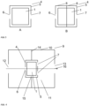
- the invention also relates to an exhaust silencer comprising a one-piece flow-through body according to the invention or a flow-through body equipped according to the invention according to the preceding embodiments, a first silencer chamber and a second silencer chamber and a partition wall, wherein the partition wall is arranged between the first and the second silencer chamber and has a connecting opening, wherein the flow-through body is arranged in the connecting opening.
- the exhaust silencer may also include a catalyst as previously described.
- An exhaust silencer typically comprises an exhaust inlet, an exhaust outlet, and a flow-through body arranged between the exhaust inlet and the exhaust outlet in the direction of exhaust flow.
- the entire exhaust gas flows through the flow-through body during use.
- the exhaust silencer is, in particular, the exhaust silencer of a two-stroke engine or a mixture-lubricated four-stroke engine.
- the exhaust gas may contain oil.
- the specified design of an exhaust silencer with a catalytic converter is particularly advantageous for such internal combustion engines.
- the exhaust silencer can also be used for separately lubricated internal combustion engines, in particular for separately lubricated four-stroke engines.
- the exhaust silencer is particularly advantageous for power generators or hand-held tools such as a chainsaw, a power cutter, a brush cutter, a blower, a lawnmower, a sprayer, or the like.
- exhaust silencers in hand-held implements differ in many respects from those in the automotive sector, for example. Due to the limited space available, exhaust silencers in such hand-held implements must be comparatively small. At the same time, operator contact with hot parts of the implement must be avoided. Therefore, strict requirements also apply with regard to exhaust gas temperatures.
- the at least one inlet opening of the catalyst is arranged in or adjacent to the first silencer chamber and the at least one outlet opening of the catalyst is arranged in or adjacent to the second silencer chamber.
- the volume of the flow-through body is no more than 70% of the volume enclosed by the exhaust silencer, in particular no more than 50%. It may be particularly advantageous if the volume of the flow-through body is no more than 30% of the volume enclosed by the exhaust silencer, since then the pressure loss of the exhaust gas during flow is minimal.
- the BET specific surface area was determined with nitrogen as adsorbate at 77 K according to BET theory (multi-point method, ISO 9277:2010).
- the pore volume and pore diameter distribution were determined using mercury porosimetry according to ISO 15901-1:2022.
- a cuboid wire body (45 x 25 x 15 mm) made of a steel wire (1.4767, 0.35 mm diameter) was first homogeneously coated with a precious metal-free washcoat layer.
- the wire body was immersed in the washcoat suspension (aqueous suspension of Al 2 O 3 and cerium hydroxide), centrifuged, and calcined at 800 °C (VB0).
- the pretreated wire bodies were treated with a solution of Pt nitrate in water (3.5 wt% Pt).
- the untreated solution showed no thixotropic behavior and a static and dynamic viscosity of ⁇ 1 mPa*s.
- the aqueous precious metal solution was thickened with 2 wt.% Natrosol and 0.5% triethylamine.
- the dynamic viscosity of the solution was 350 mPa*s, and the thixotropy index was 86.
- the measurement curve for determining the viscosity of the thickened solution is shown in Figure 5 shown.
- a pretreated wire body was completely immersed in the aqueous platinum solution.
- the impregnated wire body was then calcined in air at 800 °C.
- the total platinum dose was 60 mg.
- the aqueous platinum solution was pipetted into the pretreated wire body in a channel-like manner. Reproducible coating of the wire body was not possible because the solution partially permeated the wire body and, furthermore, capillary action prevented it from being applied in a targeted manner.
- the thickened platinum solution was pipetted into the pretreated wire body in a channel-shaped manner. A weighing check ensured that the entire solution remained on the wire body. The wire body was then calcined as described in VB1.
- the platinum dose was 15 mg.
- the coated wire bodies were installed downstream of an engine in the exhaust pipe.
- a two-stroke engine was used for the tests, operating at varying air-fuel ratios (lambda values below 1).
- the temperature and composition of the exhaust gases from the exhaust pipe were measured while the engine was running.
- Figure 6 shows the reduction in HC and NOx emissions of the differently coated wire meshes for different air-fuel mixtures. The percentage emissions are shown compared to an uncoated catalyst (VB0).
- EB1 wire mesh selectively coated according to the invention
- EB1 contained only a quarter of the precious metal inventory, it sufficiently reduced the pollutant concentration by half across the lambda range compared to the uniformly coated wire mesh (VB1).
- Figure 7 compares the increase in exhaust gas temperature when using the wire mesh (EB1) equipped according to the invention with the fully coated wire mesh (VB1) compared to a wire mesh without catalytically active precious metal (VB0).
- the exhaust gas temperature with EB1 was significantly lower than with the comparable homogeneously coated wire mesh VB1.
- a lower temperature generally means an improvement in long-term stability.
Landscapes
- Chemical & Material Sciences (AREA)
- Engineering & Computer Science (AREA)
- Chemical Kinetics & Catalysis (AREA)
- Materials Engineering (AREA)
- Organic Chemistry (AREA)
- Health & Medical Sciences (AREA)
- Toxicology (AREA)
- Combustion & Propulsion (AREA)
- Mechanical Engineering (AREA)
- General Engineering & Computer Science (AREA)
- Catalysts (AREA)
Priority Applications (2)
| Application Number | Priority Date | Filing Date | Title |
|---|---|---|---|
| EP23197582.2A EP4523788A1 (fr) | 2023-09-15 | 2023-09-15 | Procédé d'équipement ciblé d'une zone partielle d'un corps d'écoulement pourvu de métal noble et corps d'écoulement équipé d'une pièce de métal noble |
| PCT/EP2024/070819 WO2025056225A1 (fr) | 2023-09-15 | 2024-07-23 | Procédé d'équipement spécifique d'une sous-région d'un corps à écoulement traversant avec un métal précieux, et corps à écoulement traversant monobloc équipé d'un métal précieux |
Applications Claiming Priority (1)
| Application Number | Priority Date | Filing Date | Title |
|---|---|---|---|
| EP23197582.2A EP4523788A1 (fr) | 2023-09-15 | 2023-09-15 | Procédé d'équipement ciblé d'une zone partielle d'un corps d'écoulement pourvu de métal noble et corps d'écoulement équipé d'une pièce de métal noble |
Publications (1)
| Publication Number | Publication Date |
|---|---|
| EP4523788A1 true EP4523788A1 (fr) | 2025-03-19 |
Family
ID=88097754
Family Applications (1)
| Application Number | Title | Priority Date | Filing Date |
|---|---|---|---|
| EP23197582.2A Pending EP4523788A1 (fr) | 2023-09-15 | 2023-09-15 | Procédé d'équipement ciblé d'une zone partielle d'un corps d'écoulement pourvu de métal noble et corps d'écoulement équipé d'une pièce de métal noble |
Country Status (2)
| Country | Link |
|---|---|
| EP (1) | EP4523788A1 (fr) |
| WO (1) | WO2025056225A1 (fr) |
Citations (5)
| Publication number | Priority date | Publication date | Assignee | Title |
|---|---|---|---|---|
| JP2009156158A (ja) | 2007-12-26 | 2009-07-16 | Husqvarna Zenoah Co Ltd | エンジンのマフラ及び触媒装置 |
| DE102010007499A1 (de) * | 2010-02-09 | 2011-08-11 | Umicore AG & Co. KG, 63457 | Volumetrische Beschichtungsanordnung |
| US20120183460A1 (en) | 2009-10-28 | 2012-07-19 | Jesper Norsk | Process and apparatus for purification of an exhaust gas from an internal combustion engine |
| CN103372522A (zh) * | 2012-04-26 | 2013-10-30 | 发那科株式会社 | 机器人涂布系统 |
| CN104588036A (zh) | 2015-01-29 | 2015-05-06 | 无锡威孚环保催化剂有限公司 | 通用小型汽油机尾气净化金属丝饼状催化剂及其制备方法 |
-
2023
- 2023-09-15 EP EP23197582.2A patent/EP4523788A1/fr active Pending
-
2024
- 2024-07-23 WO PCT/EP2024/070819 patent/WO2025056225A1/fr not_active Ceased
Patent Citations (5)
| Publication number | Priority date | Publication date | Assignee | Title |
|---|---|---|---|---|
| JP2009156158A (ja) | 2007-12-26 | 2009-07-16 | Husqvarna Zenoah Co Ltd | エンジンのマフラ及び触媒装置 |
| US20120183460A1 (en) | 2009-10-28 | 2012-07-19 | Jesper Norsk | Process and apparatus for purification of an exhaust gas from an internal combustion engine |
| DE102010007499A1 (de) * | 2010-02-09 | 2011-08-11 | Umicore AG & Co. KG, 63457 | Volumetrische Beschichtungsanordnung |
| CN103372522A (zh) * | 2012-04-26 | 2013-10-30 | 发那科株式会社 | 机器人涂布系统 |
| CN104588036A (zh) | 2015-01-29 | 2015-05-06 | 无锡威孚环保催化剂有限公司 | 通用小型汽油机尾气净化金属丝饼状催化剂及其制备方法 |
Also Published As
| Publication number | Publication date |
|---|---|
| WO2025056225A1 (fr) | 2025-03-20 |
Similar Documents
| Publication | Publication Date | Title |
|---|---|---|
| EP0291704B1 (fr) | Revêtement à effet catalytique de materiau filtrant pour filtre à suie de moteur Diesel | |
| DE4021570C2 (fr) | ||
| DE60115363T2 (de) | Katalysator zur abgasreinigung und verfahren zu seiner herstellung | |
| DE69936631T2 (de) | Mehrschichtiger Edelmetall-enthaltender Abgaskatalysator und seine Herstellung | |
| EP0459534B1 (fr) | Catalyseur monolythique, respectivement à structure nid d'abeilles | |
| DE60201514T2 (de) | Katalytischer abgasfilter für teilchen eines dieselmotors | |
| DE69818777T2 (de) | Katalytische Legierung auf der Basis von beschichteten metallischen Teilchen und Herstellungsverfahren | |
| DE4402436A1 (de) | Katalysator zur Abgasreinigung | |
| DE19804587A1 (de) | Katalysator zur Abgasreinigung und Verfahren zu dessen Herstellung | |
| EP0556554A2 (fr) | Dispersion de revêtement pour catalyseurs d'épuration des gaz d'échappement | |
| WO2008022967A1 (fr) | filtre à particules diesel revêtu catalytiquement, procédé pour sa fabrication et utilisation du filtre | |
| DE19739925A1 (de) | Katalysator für die Abgasreinigung, Herstellverfahren für den Katalysator, Abgasreinigungsfilter und Abgasreinigungsvorrichtung | |
| DE102017214566A1 (de) | Abgaskatalysatoren mit altersunterdrückenden katalysatoren | |
| DE60316065T2 (de) | Katalysator zum Reinigen von Abgasen | |
| EP0870531A1 (fr) | Catalysateur de gaz d'échappement de véhicule | |
| DE102018100092B4 (de) | Verfahren zur Herstellung eines sinter-beständigen Katalysatorsystems | |
| WO2012059423A1 (fr) | Catalyseur d'oxydation de l'ammoniac avec une faible formation de sous-produit n2o | |
| DE60030198T2 (de) | Verfahren zur Herstellung eines Dreiwegkatalysators | |
| DE102017125040A1 (de) | Kohlenwasserstoffinjektion durch kleinporigen cu-zeolith-katalysator | |
| DE602005002388T2 (de) | Vorrichtung und Verfahren zur Reinigung von Abgas | |
| DE3436400C2 (fr) | ||
| DE102017115905A1 (de) | Oxidationskatalysator für einen Kompressionszündungsmotor und Verfahren zur Herstellung hiervon | |
| DE19713432A1 (de) | Material für einen Abgasreinigungskatalysator, ein dieses Material enthaltender Abgasreinigungskatalysator und Verfahren zu deren Herstellung | |
| DE69133164T2 (de) | Vergiftungsbeständige katalytische Zusammensetzung | |
| DE69835573T2 (de) | Abgasreinigungskatalysator für einen Verbrennungsmotor |
Legal Events
| Date | Code | Title | Description |
|---|---|---|---|
| PUAI | Public reference made under article 153(3) epc to a published international application that has entered the european phase |
Free format text: ORIGINAL CODE: 0009012 |
|
| STAA | Information on the status of an ep patent application or granted ep patent |
Free format text: STATUS: REQUEST FOR EXAMINATION WAS MADE |
|
| 17P | Request for examination filed |
Effective date: 20230915 |
|
| AK | Designated contracting states |
Kind code of ref document: A1 Designated state(s): AL AT BE BG CH CY CZ DE DK EE ES FI FR GB GR HR HU IE IS IT LI LT LU LV MC ME MK MT NL NO PL PT RO RS SE SI SK SM TR |