EP4524072A2 - Klebevorrichtung für eine kastenformmaschine und zugehöriges klebeverfahren - Google Patents
Klebevorrichtung für eine kastenformmaschine und zugehöriges klebeverfahren Download PDFInfo
- Publication number
- EP4524072A2 EP4524072A2 EP25155533.0A EP25155533A EP4524072A2 EP 4524072 A2 EP4524072 A2 EP 4524072A2 EP 25155533 A EP25155533 A EP 25155533A EP 4524072 A2 EP4524072 A2 EP 4524072A2
- Authority
- EP
- European Patent Office
- Prior art keywords
- blank
- segments
- feed plane
- guides
- jaws
- Prior art date
- Legal status (The legal status is an assumption and is not a legal conclusion. Google has not performed a legal analysis and makes no representation as to the accuracy of the status listed.)
- Pending
Links
Images


Classifications
-
- B—PERFORMING OPERATIONS; TRANSPORTING
- B31—MAKING ARTICLES OF PAPER, CARDBOARD OR MATERIAL WORKED IN A MANNER ANALOGOUS TO PAPER; WORKING PAPER, CARDBOARD OR MATERIAL WORKED IN A MANNER ANALOGOUS TO PAPER
- B31B—MAKING CONTAINERS OF PAPER, CARDBOARD OR MATERIAL WORKED IN A MANNER ANALOGOUS TO PAPER
- B31B50/00—Making rigid or semi-rigid containers, e.g. boxes or cartons
- B31B50/60—Uniting opposed surfaces or edges; Taping
- B31B50/62—Uniting opposed surfaces or edges; Taping by adhesives
- B31B50/624—Applying glue on blanks
-
- B—PERFORMING OPERATIONS; TRANSPORTING
- B31—MAKING ARTICLES OF PAPER, CARDBOARD OR MATERIAL WORKED IN A MANNER ANALOGOUS TO PAPER; WORKING PAPER, CARDBOARD OR MATERIAL WORKED IN A MANNER ANALOGOUS TO PAPER
- B31B—MAKING CONTAINERS OF PAPER, CARDBOARD OR MATERIAL WORKED IN A MANNER ANALOGOUS TO PAPER
- B31B50/00—Making rigid or semi-rigid containers, e.g. boxes or cartons
- B31B50/02—Feeding or positioning sheets, blanks or webs
- B31B50/022—Holders for feeding or positioning blanks or webs
-
- B—PERFORMING OPERATIONS; TRANSPORTING
- B31—MAKING ARTICLES OF PAPER, CARDBOARD OR MATERIAL WORKED IN A MANNER ANALOGOUS TO PAPER; WORKING PAPER, CARDBOARD OR MATERIAL WORKED IN A MANNER ANALOGOUS TO PAPER
- B31B—MAKING CONTAINERS OF PAPER, CARDBOARD OR MATERIAL WORKED IN A MANNER ANALOGOUS TO PAPER
- B31B50/00—Making rigid or semi-rigid containers, e.g. boxes or cartons
- B31B50/02—Feeding or positioning sheets, blanks or webs
- B31B50/04—Feeding sheets or blanks
- B31B50/042—Feeding sheets or blanks using rolls, belts or chains
-
- B—PERFORMING OPERATIONS; TRANSPORTING
- B31—MAKING ARTICLES OF PAPER, CARDBOARD OR MATERIAL WORKED IN A MANNER ANALOGOUS TO PAPER; WORKING PAPER, CARDBOARD OR MATERIAL WORKED IN A MANNER ANALOGOUS TO PAPER
- B31B—MAKING CONTAINERS OF PAPER, CARDBOARD OR MATERIAL WORKED IN A MANNER ANALOGOUS TO PAPER
- B31B50/00—Making rigid or semi-rigid containers, e.g. boxes or cartons
- B31B50/02—Feeding or positioning sheets, blanks or webs
- B31B50/04—Feeding sheets or blanks
- B31B50/044—Feeding sheets or blanks involving aligning
-
- B—PERFORMING OPERATIONS; TRANSPORTING
- B65—CONVEYING; PACKING; STORING; HANDLING THIN OR FILAMENTARY MATERIAL
- B65H—HANDLING THIN OR FILAMENTARY MATERIAL, e.g. SHEETS, WEBS, CABLES
- B65H9/00—Registering, e.g. orientating, articles; Devices therefor
- B65H9/10—Pusher and like movable registers; Pusher or gripper devices which move articles into registered position
- B65H9/101—Pusher and like movable registers; Pusher or gripper devices which move articles into registered position acting on the edge of the article
-
- B—PERFORMING OPERATIONS; TRANSPORTING
- B65—CONVEYING; PACKING; STORING; HANDLING THIN OR FILAMENTARY MATERIAL
- B65H—HANDLING THIN OR FILAMENTARY MATERIAL, e.g. SHEETS, WEBS, CABLES
- B65H2701/00—Handled material; Storage means
- B65H2701/10—Handled articles or webs
- B65H2701/17—Nature of material
- B65H2701/176—Cardboard
- B65H2701/1764—Cut-out, single-layer, e.g. flat blanks for boxes
Definitions
- This invention relates to a gluing device for a box forming machine and to a related gluing method.
- the invention relates to the technical field of industrial processing of sheets of paper or cardboard for forming finely finished, quality boxes.
- These boxes are made from specially shaped sheets, called blanks, consisting of a base and a plurality of segments (or panels) connected to the base and foldable relative to it to make up a sidewall of the box.
- the number of segments of the blank is equal to the number of sides of the base and each segment is connected to a respective side of the base.
- This type of blank may be generally referred to as “petalled”, like a flower.
- Blanks of other shapes are also used, however.
- the number of segments may be equal to (or greater than) the number of sides of the base, but the number of segments connected directly to the base may be less than the number of sides of the base since some of the segments may be connected to other segments.
- the blank is referred to as "H-shaped” or “T-shaped” or “cross-shaped”, depending on the configuration adopted by the blank when it is laid out flat.
- the segments are greater in number than the sides of the base, some of the segments are associated with other segments and are foldable sideways to cover the same face of the sidewall of the box, each enclosing a respective vertical edge of that face.
- the industrial process starting with the blank and ending with the finished box comprises two distinct steps: a step of forming the box, followed by a step of covering the box by applying a covering sheet to it.
- This invention relates specifically to the step of forming the box.
- the forming step in turn comprises two successive steps: a first step of folding, followed by a step of sealing or closing.
- the segments of the blank (which is laid out flat to start with) are folded about the perimeter of the base to form the sidewall of the box.
- the sidewall of the box defines as many lateral edges as there are corners of the base.
- At least two are defined by a pair of adjacent lateral borders belonging to consecutive folded segments.
- box forming machines usually comprise a vertically movable die which is operatively coupled to an inner surface of the base (or of the sidewall of the box) to fold the segments of the blank by causing them to interact with fixed contact members.
- a step of sealing follows by which the open lateral edges of the box sidewall are joined (that is, closed).
- sealing occurs by applying sealing strips (called “stay tapes”) to the open lateral edges in order to close them.
- box forming machines usually comprise sealing heads having respective sealing tape dispensers and applicator elements ("pressers") designed to apply strips of sealing tape to corresponding open lateral edges of the box.
- the sealing heads can move towards and away from the box between a non-interference position where they are clear of the box and a sealing position where they operate on the corresponding open lateral edges to press the tapes against respective lateral edges of the box, thereby sealing them.
- the function of the die is that of defining a constraining element operatively inserted snugly into the space inside the box during the action of the pressers, thereby preventing the pressers from deforming the sidewall of the box.
- hot-melt glue is distributed along the vertical edges of the sidewall of the box, in the interstices formed by the borders of the pairs of segments placed side by side. In practice, this forms a bead of glue which joins the end borders of the joined segments to form the corresponding edges of the sidewall.
- the pressers are then moved forward to abut against the edges, with the further important function of cooling the glue.
- the solution which involves spreading hot-melt glue along the gap formed by the borders of the folded segments to form the edges of the sidewall of the box avoids the use of the stay tapes, thereby improving the aesthetic appearance of the box, but is inconvenient because it is particularly complicated (and hence relatively unreliable).
- the complication is due, for example, to the need to cool the glue and the difficulty of spreading the glue precisely in the interstices.
- the free sides of some lateral segments are bevelled to define oblique faces contained in the thickness of the blank.
- the glue is spread on all the oblique faces defined by the bevels (and thus along all the sides of the base and along the sides of the segments) when the blank is laid out flat horizontally (and thus, before the segments are folded to form the vertical edges of the box).
- a supporting structure configured to enable the blank to move in a feed plane along a longitudinal feed direction to convey it to a gluing station.
- This method has a twofold advantage: on the one hand it allows production of boxes whose sharp edges have none of the aesthetic flaws due to the stay tapes, and on the other, it avoids the complications associated with spreading hot melt glue along interstices of vertical edges.
- the gluing system of the special V-grooved blank described in patent document US6029884 has some limitations which make it unsuitable for use in an automatic box forming machine.
- US2007/199648A discloses a method for producing blanks from cardboards.
- This invention has for an aim to provide a blank gluing device for an automatic box forming machine which overcomes the above mentioned disadvantages of the prior art.
- Another aim of this invention is to provide a blank gluing device for an automatic box forming machine which is particularly rapid.
- a further aim of this invention is to provide a method for gluing flat blanks which is particularly precise and suitable for use in a box forming process implemented by automatic machinery.
- the gluing device is a gluing device for a box forming machine and is configured to apply liquid glue to a flat blank of paper or cardboard having a base and a plurality of segments connected to the base and foldable to form a box sidewall, where the free sides of the segments, designed to be joined to form the edges of the box sidewall, are bevelled to define oblique faces contained in the thickness of the segments.
- the gluing device comprises:
- the supporting structure comprises:
- the guides are configured to support the end portions of blank segments and, in particular, the guides are spaced from each other to define an empty space between them.
- the predetermined direction of moving the at least one nozzle is perpendicular to the longitudinal blank feed direction defined by the supporting structure.
- the device preferably comprises a pair of nozzles which are spaced along the longitudinal direction.
- the pair of nozzles is positioned at a variable distance along the axis parallel to the longitudinal blank feed direction defined by the supporting structure. This makes changeover particularly easy.
- the positioning means are provided with adjusters which make changeover of the device particularly quick and easy, as described in more detail below.
- the locking means are important for the precision and reliability of the device.
- the locking means guarantee that while the glue is being spread the blank does not undergo deformation or bending (moving under the force of gravity outside the feed plane) which would prevent the glue from being correctly spread on the oblique faces of the edges (it should be noted that the V-shaped grooves formed on the blank weaken it and make it particularly susceptible to such deformation).
- the gluing device is enabled and the system for applying stay tapes is disabled.
- the blank is of a traditional type (without V-shaped grooves)
- the gluing device is disabled and the system for applying stay tapes is enabled.
- the invention also provides a gluing method for applying liquid glue to a flat blank of paper or cardboard having a base and a plurality of segments connected to the base and foldable to form a box sidewall, where the free sides of the segments, designed to be joined to form the edges of the box sidewall, are bevelled to define oblique faces contained in the thickness of the segments.
- the method comprises the following steps:
- the numeral 1 in the drawings denotes a box forming machine according to this invention.
- the forming machine 1 is a machine for forming boxes of paper or cardboard from flat blanks 2 (of paper or cardboard), having a base 3 and a plurality of segments 4 connected to the base 3 and foldable to form a box sidewall.
- the forming machine 1 is set up to use special blanks 2 having the features described below (illustrated in Figures 6 and 7 ).
- the free sides of the segments 4, which are intended to be joined to form the sidewall of the box, are bevelled to define oblique faces 5 contained in the thickness of the segments 4.
- this special blank (hereinafter referred to simply as "blank”, for short) is made from a sheet on whose top face V-shaped grooves are formed (for example by cutting) along straight trajectories comprising (defined by) the sides of the base 3.
- the sides of the base 3 and the sides of the segments 4 connected to corresponding sides of the base 3 are also bevelled to define oblique faces contained in the thickness of the base 3 and of the segments 4, respectively.
- these oblique faces 5, 6 are inclined at an angle of approximately 45 degrees to the plane defined by the blank 2. That way, when the segments 4 are folded relative to the base to form a right angle, the lateral oblique faces 5 of the segments 4 and the oblique faces 6 of the base 3 come into contact with each other.
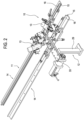
- the forming machine 1 (illustrated schematically in Figure 1 ) comprises:
- the manipulating means comprise a die 8 shaped to snugly occupy the inside of the box and connected to a motor-driven shaft 9 which moves it along a predetermined vertical axis (according to a substantially known method).
- the invention has for an object the gluing device 10 as well as the forming machine 1 which incorporates the device 10.
- the device is designed to be connected to a traditional forming machine 1 in order to modify it to make it particularly suitable for forming boxes from the (special) blanks 2.
- the gluing device 10 comprises:
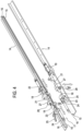
- the supporting structure 11 is illustrated in detail in Figures 4 , 8 and 9 .
- the supporting structure 11 comprises a first and a second guide 14 positioned longitudinally in the feed plane of the blank 2 to define the longitudinal direction of movement of the blanks 2.
- Each guide 14 is shaped in such a way as to prevent transversal movements of the blank 2 (that is, movements perpendicular to the longitudinal direction of movement and contained in the feed plane).
- each guide 14 is shaped to slidably support a portion of the blank 2. More specifically, the guide 14 is shaped in such a way as to slidably support a lateral end portion of one of the segments 4 of the blank 2.
- each guide 14 has an L-shaped or C-shaped profile, the guides 14 being opposed to one another.
- each guide 14 comprises a ledge 15, which lies in the feed plane, for slidably supporting the lateral portions of the blank 2.
- each guide 14 comprises a wall 16 perpendicular to the ledge 15 (and to the feed plane).
- the supporting structure 11 also comprises brackets (not illustrated) for connecting the guides 14 to a frame of the machine 1.
- the guides 14 and, more generally speaking, the supporting structure 11
- the forming machine 1 (that is, the gluing device 10) also comprises a pushing element (not illustrated, of per se known type, consisting for example of a finger connected to an actuator) movable longitudinally between the guides 14 to move the blank forward along the guides 14 towards the gluing station.
- a pushing element not illustrated, of per se known type, consisting for example of a finger connected to an actuator
- the predetermined longitudinal position is, more specifically, a position of alignment with a predetermined reference axis perpendicular to the feed plane and consisting preferably of the axis (vertical) along which the die 8 moves.
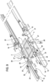
- the positioning means 17 comprise at least one second pusher 19 positioned at a predetermined distance from the first pusher 18 along the longitudinal direction, the first pusher 18 and the second pusher 19 operating on corresponding borders of segments 4 of the blank 2 (resting on the ledges 15 of the guides 14) from longitudinally opposite sides, that is, in such a way that the first pusher 18 and the second pusher 19 are positioned downstream and upstream of the blank 2 positioned in the gluing station, relative to the advancing direction of the blank along the longitudinal direction.
- the blank 2 positioned in the gluing station is longitudinally interposed between the first pusher 18 and the second pusher 19.
- the positioning means 17 of the supporting structure 11 comprise a pair of first pushers 18 and a pair of second pushers 19.
- the positioning means 17 comprise a total of four pushers operating on both the segments 4 (transversely opposed and resting on the ledges 15 of the guides 14), on the opposite transversal sides of the selfsame segments 4.
- the second pushers 19, too, are preferably associated with the guides 14.
- the pushers 18 and 19 are configured to interact with corresponding transversely positioned borders of the blank segments 4 resting on (the ledges 15 of the) guide 14.
- the pushers 18 and 19 are movable longitudinally between an extended position where they abut against the borders of the blank 2 when the blank 2 is at the predetermined longitudinal position and a withdrawn position where they are away from the blank 2.
- the pushers 18 and 19 are shown in the extended position in Figure 8 and in the withdrawn position in Figure 9 .
- the ends of the first pushers 18, that is the pushers 18 positioned downstream define flat portions 20 positioned perpendicularly to the feed plane (to provide a better grip on the borders of the segments 4).
- the second pushers 19, that is, the pushers 19 located upstream (of the blank 2 positioned in the gluing station), have teeth 21 (pivotally connected to the end of a stem, that is, of a piston, of a corresponding second pusher 19) which are movable between a first operating position where they are spaced from the feed plane of the blank 2 so as not to interfere with blank feed, and a second operating position where they intersect the feed plane so as to define an abutment for the transversal border of the blank 2.
- the teeth 21 of the second pushers 19 oscillate freely. That way, the blank 2 itself, as it advances along the longitudinal direction towards the gluing station, moves the teeth 21 to the first operating position. Then, once the blank 2 has passed them, the teeth 21 return to the second operating position by gravity (the second operating position being a position of equilibrium into which the teeth 21 tend to move when no external forces are applied to them).
- the second pushers 19 are also equipped with stops 22.
- the teeth 21 abut against the stops 22 when they are at the second operating position.
- the stops 22 are configured to prevent the teeth 21 from rotating in response to a pushing action (for example from the blank 2) backwards away from the gluing station along the longitudinal direction.
- any other suitable system may be used to allow the teeth 21 to move from the second operating position to the first only when the blank 2 passes as it advances towards the gluing station, preventing this movement in response to a force tending to move the blank backwards in the opposite direction.
- This adjustment system has two functions.
- a first function is that of aligning the positioning means 17 relative to a vertical axis (that is, perpendicular to the feed plane which the guides 14 lie in) of the forming machine 1, for example, relative to the vertical axis of movement of the die 8.
- a second function is that of adjusting the distance (along the longitudinal direction) between the first pushers 18 and the second pushers 19, in order to adapt the positioning means 17 to different box sizes.
- the pushers 18 and 19 have a predetermined stroke (length of movement of the stem, or piston, relative to the cylinder).
- the predetermined stroke (fixed) is determined during a preliminary step of calibrating the gluing device 10 (described in detail below).
- the supporting structure 11 comprises locking means 26 operating on the blank 2 for holding the blank in place so it is in the same plane as the feed plane while it is in the predetermined longitudinal position (determined by the positioning means 17).
- the jaws of the locking means 26 are configured to interact with the ledges 15 so as to press the lateral end portions (of the segments 4) of the blank 2 (these end portions being operatively interposed between the jaws 27 and the ledges).
- the jaws 27 are connected to corresponding actuators 28.
- the actuators 28 (for example, pneumatic) are preferably associated with the guides 14.
- the actuators 28 for example, pneumatic
- the guides 14 are preferably associated with the guides 14.
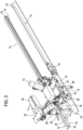
- the gluing nozzles 13 and the supporting and movement system 12 for the nozzles 13 attention is drawn to the following (with reference in particular to Figures 2 , 3 and 5 ).
- the locking means 26 are defined by a plate positioned in a zone under the blank 2 and movable vertically, acting in conjunction with the die 8 or other contact member (smaller than the die 8) positioned in the zone above the blank 2 and movable vertically.
- the plate and the contact member can be moved towards each other in such a way as to hold in between them a central portion of the base 3 of the blank 2.
- the supporting system 12 for the nozzles 13 preferably comprises a bracket 29 having a first end which can be anchored to the frame of the forming machine 1 or to the supporting structure 11.
- the bracket 29 is positioned relative to the guides 14 in such a way that it rises up (substantially perpendicularly) from the feed plane.
- a rod 32 is movably connected in cantilever fashion to a second end 31 of the bracket 29.
- the rod 32 is connected to the bracket 29 movably so it can be translated in a predetermined direction parallel to the feed plane (that is, to the plane in which blank 2 lies).
- the supporting and movement system 12 for the nozzles 13 is positioned in such a way that the rod 32 is movable along a transversal direction, that is, a direction perpendicular to the longitudinal direction of movement of the blank 2 along the guides 14.
- the supporting and movement system 12 for the nozzles 13 is positioned laterally of one of the two guides 14.
- the rod 32 is movable in both directions.
- the rod 32 is slidably coupled to a guide block 33 fixed to the bracket 29.
- the rod 32 is driven by an electric motor 34.
- the rod 32 defines a rack coupled to the electric motor 34 through the agency of a pinion.
- the nozzles 13 (the at least one nozzle 13) are connected to the free end of the rod 32.
- the nozzles (the at least one nozzle) 13 are inclined with respect to the feed plane (at angles of approximately 45 degrees); preferably, the nozzles are directed in such a way as to converge (in the glue emitting direction). Hence, the nozzle 13 is inclined with respect to the feed plane in such a way as to spread the glue perpendicularly (substantially) perpendicularly to the corresponding oblique face 5 (of the bevelled edge).
- the nozzles 13 dispense liquid, hot-melt glue of a per se known type.
- the nozzles 13 are adjustably mounted on the rod 32 so that their angle of inclination can be varied.
- the nozzles 13 are adjustably mounted on the rod 32 so that the distance between the nozzles 13 themselves can be varied.
- the nozzles 13 can be anchored along slots 36 defined by the bar 35 and extending longitudinally.
- nozzles 13 are mounted with a variable spacing along an axis parallel to the longitudinal direction of blank 2 feed allows the gluing device 10 to be adapted to blanks 2 of different sizes.
- the gluing device 10 works as follows.
- a blank 2 (of the type shown in Figures 6 and 7 ) is coupled to the guides 14 in such a way that lateral end portions of two segments 4 of it (on laterally opposite sides) rest on the (ledges 15 of the) guides 14.
- the blank 2 is fed forward towards a gluing station until it is interposed between the first pushers 18 and the second pushers 19. As it moves, the blank (or more specifically, the segments 4 resting on the guides 14) interacts with the teeth 21 of the second pushers 19, pushing them to a position of non-interference solely under the action of its own passing.
- the four pushers (the first pushers 18 and the second pushers 19) are moved towards the segments 4 of the blank 2 (the lateral segments 4 resting on the guides) until abutting (when the pushers themselves reach the end of their stroke) against the transversely positioned borders of these segments (this configuration is shown in Figure 8 ).
- the first pushers 18 and the second pushers 19 advance towards the blank 2 from opposite sides (longitudinally) of the blank 2 itself in order to close it in the middle.
- the locking means 26 (which up to this moment have been inactive in the position of non-interference with the blank 2) are activated in order to lock the blank at the predetermined longitudinal position reached when the pushers 8, 9 are in abutment against the blank 2.
- first pushers 18 and the second pushers 19 withdraw longitudinally away from the blank 2 and return to a position of non-interference therewith (this situation is illustrated in Figure 8 ).
- the nozzles 13 are moved along the trajectories defined by the oblique faces 5 of the segments 4 and are activated to apply glue at least on a number of oblique faces 5 equal to half the total number of oblique faces 5 of the segments 4, so that for each pair of oblique faces 5 (belonging to different segments 4 and) combining to form an edge of the box sidewall, at least one has glue applied to it.
- the nozzles 13 are moved transversely to apply glue to all of the oblique faces 5 which are transversely positioned, while no glue is applied to the oblique faces 5 which are positioned longitudinally.
- the nozzles 13 remain active so as to spread glue also on the oblique faces 6 of the base 3 which are positioned transversely (and which are interposed between the oblique faces 5 of the segments to which glue is also applied) while, preferably, no glue is applied to the oblique faces 6 of the base 3 which are positioned longitudinally.
- the supporting structure 11 is configured in such a way that the spacing of the guides 14 can be adjusted during initial setting up of the device 10.
- the device 10 is preferably configured in such a way that a blank whose base 3 is rectangular in shape is coupled to the guides 14 with the long sides of the base positioned longitudinally.
- the blank 2 (of the required size for the boxes to be made) is positioned in the gluing station between the first pushers 18 and the second pushers 19.
- the pushers 18 and 19 are extended (to the end of their stroke) and are moved along the guides 14 until the blank 2 is at the required longitudinal position, with the pushers 18 and 19 extended and in abutment against the lateral segments 4 of the blank 2 itself.
- the positioning of the blank 2 at the predetermined longitudinal position is accomplished by moving a first pusher 18 and a second pusher 19 longitudinally in opposite directions until the selfsame pushers 18 and 19 reach an extended position where they are in abutment against corresponding borders of the blank 2 segments 4 resting on the guides (the borders being) positioned transversely to the longitudinal direction of blank 2 feed.
Landscapes
- Making Paper Articles (AREA)
- Package Closures (AREA)
- Cartons (AREA)
- Meat, Egg Or Seafood Products (AREA)
Applications Claiming Priority (5)
| Application Number | Priority Date | Filing Date | Title |
|---|---|---|---|
| IT000029A ITBO20120029A1 (it) | 2012-01-25 | 2012-01-25 | Dispositivo incollatore per una macchina formatrice di scatole e relativo metodo di incollaggio |
| EP19159315.1A EP3513960B1 (de) | 2012-01-25 | 2012-12-18 | Klebevorrichtung für eine kastenformmaschine und zugehöriges klebeverfahren |
| EP17171930.5A EP3246154B1 (de) | 2012-01-25 | 2012-12-18 | Klebevorrichtung für eine kastenformmaschine und eine kastenformmaschine |
| PCT/IB2012/057421 WO2013110986A1 (en) | 2012-01-25 | 2012-12-18 | Gluing device for a box forming machine and related gluing method |
| EP12820929.3A EP2807020B1 (de) | 2012-01-25 | 2012-12-18 | Klebevorrichtung für eine kastenformmaschine und zugehöriges klebeverfahren |
Related Parent Applications (3)
| Application Number | Title | Priority Date | Filing Date |
|---|---|---|---|
| EP12820929.3A Division EP2807020B1 (de) | 2012-01-25 | 2012-12-18 | Klebevorrichtung für eine kastenformmaschine und zugehöriges klebeverfahren |
| EP17171930.5A Division EP3246154B1 (de) | 2012-01-25 | 2012-12-18 | Klebevorrichtung für eine kastenformmaschine und eine kastenformmaschine |
| EP19159315.1A Division EP3513960B1 (de) | 2012-01-25 | 2012-12-18 | Klebevorrichtung für eine kastenformmaschine und zugehöriges klebeverfahren |
Publications (2)
| Publication Number | Publication Date |
|---|---|
| EP4524072A2 true EP4524072A2 (de) | 2025-03-19 |
| EP4524072A3 EP4524072A3 (de) | 2025-07-23 |
Family
ID=45992622
Family Applications (4)
| Application Number | Title | Priority Date | Filing Date |
|---|---|---|---|
| EP17171930.5A Active EP3246154B1 (de) | 2012-01-25 | 2012-12-18 | Klebevorrichtung für eine kastenformmaschine und eine kastenformmaschine |
| EP25155533.0A Pending EP4524072A3 (de) | 2012-01-25 | 2012-12-18 | Klebevorrichtung für eine kastenformmaschine und zugehöriges klebeverfahren |
| EP12820929.3A Active EP2807020B1 (de) | 2012-01-25 | 2012-12-18 | Klebevorrichtung für eine kastenformmaschine und zugehöriges klebeverfahren |
| EP19159315.1A Active EP3513960B1 (de) | 2012-01-25 | 2012-12-18 | Klebevorrichtung für eine kastenformmaschine und zugehöriges klebeverfahren |
Family Applications Before (1)
| Application Number | Title | Priority Date | Filing Date |
|---|---|---|---|
| EP17171930.5A Active EP3246154B1 (de) | 2012-01-25 | 2012-12-18 | Klebevorrichtung für eine kastenformmaschine und eine kastenformmaschine |
Family Applications After (2)
| Application Number | Title | Priority Date | Filing Date |
|---|---|---|---|
| EP12820929.3A Active EP2807020B1 (de) | 2012-01-25 | 2012-12-18 | Klebevorrichtung für eine kastenformmaschine und zugehöriges klebeverfahren |
| EP19159315.1A Active EP3513960B1 (de) | 2012-01-25 | 2012-12-18 | Klebevorrichtung für eine kastenformmaschine und zugehöriges klebeverfahren |
Country Status (9)
| Country | Link |
|---|---|
| EP (4) | EP3246154B1 (de) |
| JP (1) | JP6175077B2 (de) |
| DE (1) | DE12820929T1 (de) |
| ES (2) | ES3015062T3 (de) |
| HU (1) | HUE043596T2 (de) |
| IT (1) | ITBO20120029A1 (de) |
| PL (1) | PL3246154T3 (de) |
| PT (1) | PT3246154T (de) |
| WO (1) | WO2013110986A1 (de) |
Families Citing this family (20)
| Publication number | Priority date | Publication date | Assignee | Title |
|---|---|---|---|---|
| CN105252817A (zh) * | 2015-11-13 | 2016-01-20 | 瑞安市中法机械有限公司 | 一种全自动纸盒成型机 |
| CN105946281B (zh) * | 2016-04-26 | 2018-05-22 | 东莞市上合旺盈印刷有限公司 | 包装盒自动化组装线 |
| CN105946282A (zh) * | 2016-05-20 | 2016-09-21 | 山东泰宝防伪制品有限公司 | 一种盒中盒一次成型糊盒机 |
| DE102016006504A1 (de) | 2016-05-28 | 2017-12-14 | Kolbus Gmbh & Co. Kg | Vorrichtung zum Auftragen von Klebstoff auf vorwiegend flächige Materialzuschnitte |
| DE102016006503A1 (de) | 2016-05-28 | 2017-11-30 | Kolbus Gmbh & Co. Kg | Verfahren und Vorrichtung zum Bearbeiten vorwiegend flächiger Werkstücke |
| CN106696352B (zh) * | 2016-12-08 | 2018-11-20 | 青岛美嘉隆包装机械有限公司 | 一种装订尺寸准确的钢带箱双边锁扣装订机 |
| CN107322986A (zh) * | 2017-08-25 | 2017-11-07 | 昆山永立包装有限公司 | 一种用于包装纸板的双层刷胶粘合装置 |
| CN107458024A (zh) * | 2017-09-09 | 2017-12-12 | 芜湖润林包装材料有限公司 | 一种蜂窝板包装箱胶水涂抹机 |
| CN107877927B (zh) * | 2017-11-06 | 2024-03-12 | 终结号(深圳)科技有限公司 | 一种包盒机的自动上料方法 |
| CN108582870B (zh) * | 2018-02-14 | 2020-06-05 | 温州高晟机械有限公司 | 一种制盒机的制盒工艺 |
| CN109719994B (zh) * | 2019-03-13 | 2023-12-26 | 浙江国豪机械有限公司 | 一种包装盒成型机 |
| CN110001129A (zh) * | 2019-05-06 | 2019-07-12 | 东莞大瑞智能装备有限公司 | 一种折叠盒的喷胶装置 |
| CN110271220A (zh) * | 2019-07-30 | 2019-09-24 | 淮北市硕华机械设备有限公司 | 一种包装纸箱成型打钉装置 |
| CN110588064A (zh) * | 2019-09-30 | 2019-12-20 | 广东锐军智能设备有限公司 | 一种转盘式纸盒贴合机 |
| CN111391406A (zh) * | 2020-04-29 | 2020-07-10 | 浙江新发现机械制造有限公司 | 一种喷胶装置 |
| DE102020114818A1 (de) * | 2020-06-04 | 2021-12-09 | Kolbus Gmbh & Co. Kg | Verfahren und Vorrichtung zum Beziehen von Schachteln |
| CN112721308A (zh) * | 2020-12-30 | 2021-04-30 | 成都市裕同印刷有限公司 | 纸盒包边成型机 |
| CN114772336B (zh) * | 2022-05-11 | 2023-07-18 | 江苏美嘉包装有限公司 | 一种天地盒机及封面机纸品粘合伺服纠偏系统 |
| DE102022118080A1 (de) * | 2022-07-19 | 2024-01-25 | Cewe Stiftung & Co. Kgaa | Schuber für ein Fotobuch |
| CN117901484A (zh) * | 2024-03-20 | 2024-04-19 | 合肥众诚印刷有限公司 | 一种用于包装盒的涂胶装置及其包装盒 |
Citations (4)
| Publication number | Priority date | Publication date | Assignee | Title |
|---|---|---|---|---|
| US6029884A (en) | 1998-05-26 | 2000-02-29 | Paul T. Trend Corporation | Method for constructing a sturdy, light-tight package and a package thereof |
| US20070199648A1 (en) | 2003-06-26 | 2007-08-30 | Hulverscheidt Detlef Jr | Method for producing blanks from cardboard and device for implementing the method |
| WO2007129201A2 (en) | 2006-05-08 | 2007-11-15 | Emmeci S.P.A. | Machine for forming packing boxes, blank and packing box |
| WO2009090481A2 (en) | 2007-12-21 | 2009-07-23 | Emmeci S.P.A. | Process and machine for forming boxes |
Family Cites Families (9)
| Publication number | Priority date | Publication date | Assignee | Title |
|---|---|---|---|---|
| US3218940A (en) * | 1963-09-26 | 1965-11-23 | Pearson Co R A | Carton setting up machine |
| SE8008755L (sv) * | 1980-12-12 | 1982-06-13 | Akerlund & Rausing Ab | Smeltlim-applikator |
| JPH0777772B2 (ja) * | 1990-05-28 | 1995-08-23 | 積水化成品工業株式会社 | 組立箱材の製造方法 |
| JPH08142235A (ja) * | 1994-11-15 | 1996-06-04 | Iijima Toshimitsu | 紙製容器製造装置 |
| JPH09314700A (ja) * | 1996-06-04 | 1997-12-09 | Norio Iijima | 紙製折箱製函機 |
| FR2765191B1 (fr) * | 1997-06-26 | 1999-08-20 | Cermex | Procede et machine de collage automatique d'un film plastique thermoretractable sur le fond d'une caisse ouverte |
| JP3848844B2 (ja) * | 2001-03-30 | 2006-11-22 | 元 永井 | 紙箱製造装置 |
| JPWO2005075185A1 (ja) * | 2004-02-06 | 2007-08-02 | 元 永井 | 紙箱製造装置 |
| FR2927015B1 (fr) * | 2008-02-04 | 2010-03-05 | Otor Sa | Procede et dispositif pour la realisation de boites a partir d'un ensemble de decoupes |
-
2012
- 2012-01-25 IT IT000029A patent/ITBO20120029A1/it unknown
- 2012-12-18 JP JP2014553819A patent/JP6175077B2/ja active Active
- 2012-12-18 PL PL17171930T patent/PL3246154T3/pl unknown
- 2012-12-18 EP EP17171930.5A patent/EP3246154B1/de active Active
- 2012-12-18 PT PT17171930T patent/PT3246154T/pt unknown
- 2012-12-18 HU HUE17171930A patent/HUE043596T2/hu unknown
- 2012-12-18 WO PCT/IB2012/057421 patent/WO2013110986A1/en not_active Ceased
- 2012-12-18 EP EP25155533.0A patent/EP4524072A3/de active Pending
- 2012-12-18 EP EP12820929.3A patent/EP2807020B1/de active Active
- 2012-12-18 ES ES19159315T patent/ES3015062T3/es active Active
- 2012-12-18 ES ES17171930T patent/ES2725494T3/es active Active
- 2012-12-18 DE DE12820929.3T patent/DE12820929T1/de active Pending
- 2012-12-18 EP EP19159315.1A patent/EP3513960B1/de active Active
Patent Citations (4)
| Publication number | Priority date | Publication date | Assignee | Title |
|---|---|---|---|---|
| US6029884A (en) | 1998-05-26 | 2000-02-29 | Paul T. Trend Corporation | Method for constructing a sturdy, light-tight package and a package thereof |
| US20070199648A1 (en) | 2003-06-26 | 2007-08-30 | Hulverscheidt Detlef Jr | Method for producing blanks from cardboard and device for implementing the method |
| WO2007129201A2 (en) | 2006-05-08 | 2007-11-15 | Emmeci S.P.A. | Machine for forming packing boxes, blank and packing box |
| WO2009090481A2 (en) | 2007-12-21 | 2009-07-23 | Emmeci S.P.A. | Process and machine for forming boxes |
Also Published As
| Publication number | Publication date |
|---|---|
| DE12820929T1 (de) | 2015-09-10 |
| EP3246154B1 (de) | 2019-04-17 |
| ITBO20120029A1 (it) | 2013-07-26 |
| HUE043596T2 (hu) | 2019-08-28 |
| EP3513960C0 (de) | 2025-02-05 |
| EP2807020B1 (de) | 2017-05-24 |
| JP2015504797A (ja) | 2015-02-16 |
| WO2013110986A1 (en) | 2013-08-01 |
| EP3513960B1 (de) | 2025-02-05 |
| EP3246154A1 (de) | 2017-11-22 |
| ES2725494T3 (es) | 2019-09-24 |
| EP4524072A3 (de) | 2025-07-23 |
| PT3246154T (pt) | 2019-06-24 |
| JP6175077B2 (ja) | 2017-08-02 |
| ES3015062T3 (en) | 2025-04-29 |
| EP2807020A1 (de) | 2014-12-03 |
| PL3246154T3 (pl) | 2019-12-31 |
| EP3513960A1 (de) | 2019-07-24 |
Similar Documents
| Publication | Publication Date | Title |
|---|---|---|
| EP2807020B1 (de) | Klebevorrichtung für eine kastenformmaschine und zugehöriges klebeverfahren | |
| EP2991821B1 (de) | Maschine und verfahren zur formung von schachteln aus papier oder karton | |
| CN106347731B (zh) | 三维包装机 | |
| EP2090512A2 (de) | Faltvorrichtung und Verfahren zum Aufrichten von Schachteln mit flachen Teilen mit T-Form oder Doppel-T-Form | |
| MX2010008601A (es) | Metodo y aparato para la creacion de cajas a partir de un conjunto de recortes. | |
| EP2508353A2 (de) | Maschine zum Herstellen von Büchern, insbesondere Fotobüchern und/oder Bildbänden | |
| EP2221170B1 (de) | Vorrichtung und Verfahren zum Abdecken einer Box mit einer Bodenwand mit mehr als vier Seiten | |
| CN212920602U (zh) | 一种包装盒贴角机 | |
| US20190039256A1 (en) | Machine and method for working a material suitable to make containers | |
| EP3530449B1 (de) | Vorrichtung und verfahren zum abdecken von kartons mit unverbundenen ecken | |
| US9840057B2 (en) | Method for adjusting the radial spacing between two tools, embossing device and folder-gluer provided therewith | |
| CN111838850A (zh) | 一种口罩生产机械 | |
| JP2015525142A5 (de) | ||
| ITBO20110771A1 (it) | Procedimento ed apparato per il posizionamento di scatole di carta o cartone su fogli sbozzati di rivestimento | |
| WO2007129201A2 (en) | Machine for forming packing boxes, blank and packing box | |
| CN107433731B (zh) | 用于在主要为面状的材料坯件上涂敷胶粘剂的设备 | |
| CN106457730B (zh) | 用于制造箱子的粘合机器 | |
| WO2013098684A1 (en) | Apparatus and method for forming a box made of paper or paperboard having lateral edges of different heights | |
| EP3434609B1 (de) | Faltverfahren und -vorrichtung | |
| US20090136323A1 (en) | Device for transferring a case from a roll-down apparatus to a handover point | |
| CN216152493U (zh) | 一种薄膜自动裁切装置 | |
| JP7477259B2 (ja) | 空白紙から箱を形成するための熱密封材料の帯体を巻き出すための巻出しユニット及び方法 | |
| US1856267A (en) | Method of forming box parts | |
| ITFI20110081A1 (it) | Testa cucitrice per un'apparecchiatura formatrice di scatole | |
| ITBO20080756A1 (it) | Apparato e procedimento per la formazione di scatole in carta o cartone aventi spigoli laterali di altezza diversa. |
Legal Events
| Date | Code | Title | Description |
|---|---|---|---|
| PUAI | Public reference made under article 153(3) epc to a published international application that has entered the european phase |
Free format text: ORIGINAL CODE: 0009012 |
|
| STAA | Information on the status of an ep patent application or granted ep patent |
Free format text: STATUS: THE APPLICATION HAS BEEN PUBLISHED |
|
| AC | Divisional application: reference to earlier application |
Ref document number: 2807020 Country of ref document: EP Kind code of ref document: P Ref document number: 3246154 Country of ref document: EP Kind code of ref document: P Ref document number: 3513960 Country of ref document: EP Kind code of ref document: P |
|
| AK | Designated contracting states |
Kind code of ref document: A2 Designated state(s): AL AT BE BG CH CY CZ DE DK EE ES FI FR GB GR HR HU IE IS IT LI LT LU LV MC MK MT NL NO PL PT RO RS SE SI SK SM TR |
|
| REG | Reference to a national code |
Ref country code: DE Ref legal event code: R079 Free format text: PREVIOUS MAIN CLASS: B65H0011000000 Ipc: B31B0050620000 |
|
| PUAL | Search report despatched |
Free format text: ORIGINAL CODE: 0009013 |
|
| AK | Designated contracting states |
Kind code of ref document: A3 Designated state(s): AL AT BE BG CH CY CZ DE DK EE ES FI FR GB GR HR HU IE IS IT LI LT LU LV MC MK MT NL NO PL PT RO RS SE SI SK SM TR |
|
| RIC1 | Information provided on ipc code assigned before grant |
Ipc: B31B 50/62 20170101AFI20250618BHEP Ipc: B31B 50/02 20170101ALI20250618BHEP Ipc: B31B 50/04 20170101ALI20250618BHEP Ipc: B65H 9/10 20060101ALI20250618BHEP Ipc: B65H 11/00 20060101ALI20250618BHEP Ipc: B31B 100/00 20170101ALN20250618BHEP Ipc: B31B 110/35 20170101ALN20250618BHEP |
|
| STAA | Information on the status of an ep patent application or granted ep patent |
Free format text: STATUS: REQUEST FOR EXAMINATION WAS MADE |
|
| 17P | Request for examination filed |
Effective date: 20260116 |