EP4524094A1 - Steigbügel für reitsport mit abnehmbarer und austauschbarer lauffläche - Google Patents
Steigbügel für reitsport mit abnehmbarer und austauschbarer lauffläche Download PDFInfo
- Publication number
- EP4524094A1 EP4524094A1 EP24187444.5A EP24187444A EP4524094A1 EP 4524094 A1 EP4524094 A1 EP 4524094A1 EP 24187444 A EP24187444 A EP 24187444A EP 4524094 A1 EP4524094 A1 EP 4524094A1
- Authority
- EP
- European Patent Office
- Prior art keywords
- side arm
- support element
- stirrup
- arm
- horse riding
- Prior art date
- Legal status (The legal status is an assumption and is not a legal conclusion. Google has not performed a legal analysis and makes no representation as to the accuracy of the status listed.)
- Granted
Links
Images




Classifications
-
- B—PERFORMING OPERATIONS; TRANSPORTING
- B68—SADDLERY; UPHOLSTERY
- B68C—SADDLES; STIRRUPS
- B68C3/00—Stirrups
- B68C3/02—Stirrups with side part or sole plate attached to other parts of the stirrup movably, e.g. pivotally
-
- B—PERFORMING OPERATIONS; TRANSPORTING
- B68—SADDLERY; UPHOLSTERY
- B68C—SADDLES; STIRRUPS
- B68C3/00—Stirrups
- B68C2003/005—Foot release mechanisms
-
- B—PERFORMING OPERATIONS; TRANSPORTING
- B68—SADDLERY; UPHOLSTERY
- B68C—SADDLES; STIRRUPS
- B68C3/00—Stirrups
- B68C2003/0083—Stirrups with an anti-slip foot bar
-
- B—PERFORMING OPERATIONS; TRANSPORTING
- B68—SADDLERY; UPHOLSTERY
- B68C—SADDLES; STIRRUPS
- B68C3/00—Stirrups
- B68C2003/0091—Stirrups with an anti-slip removable sole
Definitions
- the present invention relates to a stirrup for horse riding.
- the present invention is in the field of stirrups for horse riding with a removable and interchangeable tread.
- stirrups for horse riding wherein the tread, i.e., the support portion whereupon the rider rests the foot once mounted on a horse, is attached to the stirrup frame by mechanical means, such as screws.
- An example of a stirrup of the prior art is described in the document US 2019/144260 A1 .
- a typical problem with horse riding stirrups with the tread attached to the frame by mechanical locking means is the inability of the rider to independently remove the tread.
- the rider is not able to independently change a worn and/or damaged tread insofar as the fastening thereof requires that it be made secure, an operation that may only be carried out by specialized personnel. Therefore, in order to avoid reliance upon external assistance, the rider is forced to possess a second spare stirrup, with the relative attached tread.
- a further problem with known stirrups concerns the risk of weakening the structure of the frame insofar as fastening by mechanical means requires making openings and/or holes in the frame of the stirrup with a consequent reduction in the mechanical resistance thereof to the stresses exerted by the rider during use.
- Horse riding stirrups of the prior art consequently involve high manufacturing complexity, with considerable implementation times and costs.
- the object of the present invention is to provide a horse riding stirrup which solves the drawbacks of the prior art whilst taking into account the needs of the sector.
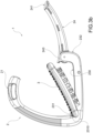
- the stirrup 1 comprises a frame 2 whereto a support element 3 for the foot of a user is removably engaged.
- a support element plane P visible in Figure 3d , is defined for reference.
- the frame 2 comprises a connection portion 21 for connecting to a bracket, a first side arm 22, and a support arm 23 connected to the first side arm 22 in an incident manner for delimiting a frame compartment 10 engageable by the foot of a user.
- the first side arm 22 and the support arm 23 are made in one piece as a single body.
- the support arm 23 defines a seat 230 whereinto the support element 3 may be inserted.
- the seat 230 is defined on one side (at the first side arm 22) by an undercut portion 231, and on the opposite side it is instead devoid of undercut portions or other transversely protruding elements.
- the frame 2 comprises a second side arm 24 comprising a joint end 241, pivoted to the frame 2 about a rotation axis R, and a free end 242 rotatable between a configuration of coupling to the frame 2, wherein the second side arm 24 at least partially encloses the frame compartment 10, and a configuration of uncoupling from the frame 2.
- the second side arm 24 has a length such that, in the coupling configuration, the free end 242 abuts against the frame 2.
- the second side arm 24 has a length such that, in the coupling configuration, it partially encloses the frame compartment 10. In other words, the second side arm 24 defines an opening between the free end 242 and the frame 2, not completely closing the frame compartment 10. In other words, the second side arm 24 is shorter than the first side arm 22.
- the stirrup 2 comprises a support element 3 for the foot of the user, mounted onto the support arm 23 inside the seat 230.
- the support element 3 comprises a first coupling portion 31 suitable for wedging below the undercut portion 231 of the support element seat 230, and a second coupling portion 32, opposite to the first coupling portion 31, intended to be engaged by a suitable locking mean 243 provided on the second side arm 24.
- the second side arm 24 comprises a locking mean 243 suitable for locking the support element 3 into the seat 230 when the second side arm 24 is in the coupling configuration.
- the locking mean 243 is a protruding flap of a substantially triangular shape having a surface suitable for defining the upper limit of the seat 230 for the support element 3 once the support element 3 is mounted onto the support arm 23.
- the locking means 243 is made in one piece with the second side arm 24.
- the locking means 243 constitutes an additional element suitable for being connected to the second side arm 24.
- the locking mean is made of a different material than that used for the second side arm 24.
- the locking mean 243 is connected to the second side arm 24 by elastic means that are suitable for moving it between an active configuration, wherein it protrudes with respect to the second side arm 24 inside the frame compartment 10 so as to define at least a portion of the seat 230 at the top, and a recessed configuration, wherein it is received at least partially in a suitable locking seat obtained in the second side arm.
- the support element 3 when the second side arm 24 is in the coupling configuration (wherein the free end 242 is in contact with the connection portion 21 of the frame 2) the support element 3 is constrained at the top by the locking mean 243, and thus held firmly in position in the seat 230.
- the locking mean 243 is a second undercut portion 233, substantially equal to and opposite to the undercut portion 231.
- the locking system of the support element 3 is represented by the locking mean 243 of the second side arm 24, without the need for separate mechanical means such as screws or other similar elements.
- the support element 3 is not constrained to the support arm 23 by one or more mechanical fastenings, such as screws extending through the frame 2. Therefore, the locking system according to the present invention allows for a support element 3 (known as tread in the sector) of the removable and interchangeable type insofar as the user, independently, is able to replace it quickly and easily by simply opening the second side arm 24 in the uncoupling configuration, up to the point of maximum rotation thereof (visible in Figure 3b ).
- the user does not therefore need to resort to the unscrewing of mechanical fastening means which could cause the reinforcing core and frame to break if not properly carried out by specialized personnel.
- the support arm 23 has in fact no mechanical fastenings passing through it in order to avoid weakening the mechanical strength thereof.
- the undercut portion 231 is arranged in a first connecting zone 41 between the first side arm 22 and the support arm 23.
- the undercut portion 231 is a protruding flap of a substantially triangular shape having a surface 2310 suitable for defining the upper limit of the seat 230 for the support element 3 once the first coupling portion 31 of the same has been wedged to the undercut portion 231.
- the seat 230 for the support element 3 is delimited on one side by the undercut portion 231 and on the opposite side by an end portion 232 without undercut portions or other transversely protruding elements.
- the end portion 232 extends in an incident direction with respect to the plane P, wherein the seat 230 of the support element 3 extends.
- the end portion 232 extends in a direction substantially perpendicular to the support element plane P.
- the support arm 23 and the end portion 232 are made in one piece as a single body. The support arm 23 and the end portion 232 identify a second joining zone 42.
- the seat 230 of the support element 3 is delimited by the undercut portion 231 at the first joining zone 41 and by the end portion 232 at the second joining zone 42.
- the end portion 232 has an inner surface, i.e., facing the frame compartment 10, which is substantially smooth, i.e., without protrusions and/or depressions.
- the frame 2 extends from the connection portion 21 to the end portion 232, and is preferably made in one piece as a single body.
- the joint end 241 of the second side arm 24 is pivoted to the support arm 23 about the rotation axis R on an opposite side with respect to the undercut portion 231.
- the joint end 241 is pivoted to the end portion 232.
- the free end 242 of the second side arm 24 is rotatable between a coupling configuration and an uncoupling configuration from the connection portion 21 wherein it is spaced apart therefrom in order to create a lateral disengagement opening of the foot of the user from said frame compartment.
- the locking means 243 is made at the joint end 241 of the second side arm 24.
- the end portion 232 comprises an access compartment 2320 suitable for containing a rotation mechanism of the second side arm 24.
- the rotation mechanism preferably comprises an elastic mean, such as a spring, which allows the second side arm to be moved from the uncoupling configuration to the coupling configuration.
- the locking mean 243 is suitable for closing the access compartment 2320 at the seat 230 in such a way as to protect the rotation mechanism from any debris and/or dust during use. This allows the rotation mechanism to be preserved, reducing the need to intervene with stirrup maintenance interventions following breakages and/or malfunctions.
- the joint end 241 is pivoted to the connection portion 21 about the rotation axis R, on an opposite side with respect to the first side arm 22.
- the free end 242 is rotatable between a coupling configuration and an uncoupling configuration from the support arm 23, wherein said second side arm 24 is spaced apart from the support arm 23 so as to create a lateral disengagement opening of the foot of the user from said frame compartment.
- the locking mean 243 is implemented at the free end 242 of the second side arm 24.
- the term coupling configuration refers to the configuration wherein the second side arm 24 is rotated so as to at least partially close the compartment 10 of the frame 2.
- the term uncoupling configuration refers to the configuration wherein the second side arm 24 is rotated so as to define a lateral access opening to the compartment 10 of the frame 2.
- the second side arm 24 is capable of switching from the coupling configuration, wherein it firmly holds the support element 3 in position ( Figure 3d ), to the uncoupling configuration wherein, when it is at the maximum opening rotation thereof, it allows for the disengagement of the support element 3 ( Figure 3b and 3c ).
- the support element 3 comprises, at the bottom, a longitudinal groove 33 suitable for being at least partially coupled in a form-fit to the seat 230 of the support element 3, visible in Figure 2 , obtained in the support arm 23.
- a longitudinal groove 33 suitable for being at least partially coupled in a form-fit to the seat 230 of the support element 3, visible in Figure 2 , obtained in the support arm 23.
- two protruding and parallel containment flaps 331 are also provided.
- the support element 3 has a plurality of protrusions 60 at the top to keep the foot of the user in position.
- the plurality of protrusions 60 creates a grip surface, i.e., greater friction between the sole of the footwear worn by the user and the support element 3.
- connection portion 21 comprises at least one hole or slot 210 which at least partially passes through the thickness of the frame 2.
- said hole 210 completely passes through the thickness of the frame 2.
- the frame 2 is made at least partially of a polymeric material.
- the frame 2 comprises a reinforcing core.
- the reinforcement core is preferably made of a metallic material.
- the polymeric material is co-molded onto the reinforcing core.
- the polymeric material is overmolded onto the reinforcing core.
- the reinforcement core 20 is completely embedded in the polymeric material 200.
- the reinforcing core extends from the connection portion 21 along the first side arm 22 and along at least part of the support arm 23.
- the reinforcing core extends from the connection portion 21, along the first side arm 22 and along the entire support arm 23.
- the reinforcing core is made in one piece as a single body which extends from the connection portion 21 to the support arm 23.
- At least one side arm between the first side arm 22 and the second side arm 24, comprises at least one groove 50 that is suitable for being engaged by a removable insert 4.
- the insert 4 is snap-fitted into the groove 50.
- the insert 4 is an accessory component used to customize the stirrup, object of the present invention.
- the user may insert an insert element 4, for example of a preferred color or with lettering or other graphical elements, to embellish and customize the horse riding stirrup thereof.
- first side arm 22 comprises the groove 50 with an insert 4.
- second side arm 24 comprises the groove 50 with an insert 4.
- both the first side arm 22 and the second side arm 24 each comprise at least one groove 5 with an insert 4.
- Object of the present invention is also a method for replacing a support element of a stirrup 1 for horse riding as described above. Such method includes the steps of:
- the horse riding stirrup according to the present invention makes it possible to have a removable and interchangeable support element thereby overcoming the typical problems of the prior art in that the rider may, independently, change said support element (known as tread in the sector) without the need to resort to specialized personnel.
- the horse riding stirrup with a removable and interchangeable tread according to the present invention allows for a reduction in production times and costs.
- the horse riding stirrup with a removable and interchangeable tread according to the present invention allows for a stirrup with greater mechanical resistance to the stresses exerted by the foot of the user to be obtained, insofar as it lacks holes or other openings for mechanical fastening means, such as screws, which would cause a considerable weakening of the reinforcing core and, more generally, of the frame.
- the stirrup according to the present invention allows for rapid replacement of the tread in the event of damage or breakage, even during a horse riding excursion: in this way the user may continue to ride thereby preserving the safety thereof.
- the stirrup according to the present invention also has a reinforcing core made in one piece, as a single body, which allows the mechanical properties of the materials used in the construction to be maintained, and reduces the possibility of structural damage to a minimum.
Landscapes
- Engineering & Computer Science (AREA)
- Mechanical Engineering (AREA)
- Seats For Vehicles (AREA)
Applications Claiming Priority (1)
| Application Number | Priority Date | Filing Date | Title |
|---|---|---|---|
| IT102023000018951A IT202300018951A1 (it) | 2023-09-14 | 2023-09-14 | Staffa per equitazione con panca removibile e intercambiabile |
Publications (3)
| Publication Number | Publication Date |
|---|---|
| EP4524094A1 true EP4524094A1 (de) | 2025-03-19 |
| EP4524094C0 EP4524094C0 (de) | 2025-12-17 |
| EP4524094B1 EP4524094B1 (de) | 2025-12-17 |
Family
ID=88838827
Family Applications (1)
| Application Number | Title | Priority Date | Filing Date |
|---|---|---|---|
| EP24187444.5A Active EP4524094B1 (de) | 2023-09-14 | 2024-07-09 | Steigbügel zum reiten mit abnehmbarer und austauschbarer trittfläche |
Country Status (2)
| Country | Link |
|---|---|
| EP (1) | EP4524094B1 (de) |
| IT (1) | IT202300018951A1 (de) |
Citations (1)
| Publication number | Priority date | Publication date | Assignee | Title |
|---|---|---|---|---|
| US20190144260A1 (en) | 2016-04-22 | 2019-05-16 | Amahorse Trading S.R.L. | Riding bracket, manufacturing method |
-
2023
- 2023-09-14 IT IT102023000018951A patent/IT202300018951A1/it unknown
-
2024
- 2024-07-09 EP EP24187444.5A patent/EP4524094B1/de active Active
Patent Citations (1)
| Publication number | Priority date | Publication date | Assignee | Title |
|---|---|---|---|---|
| US20190144260A1 (en) | 2016-04-22 | 2019-05-16 | Amahorse Trading S.R.L. | Riding bracket, manufacturing method |
Also Published As
| Publication number | Publication date |
|---|---|
| EP4524094C0 (de) | 2025-12-17 |
| EP4524094B1 (de) | 2025-12-17 |
| IT202300018951A1 (it) | 2025-03-14 |
Similar Documents
| Publication | Publication Date | Title |
|---|---|---|
| US20220363339A1 (en) | Bicycle bracket element | |
| US9545971B2 (en) | Bicycle frame made out of fiber-reinforced material comprising an adapter plate for the rear wheel | |
| US10994987B2 (en) | Riding bracket | |
| EP1347201B1 (de) | Kabelführungskette | |
| EP3216688B1 (de) | Wippe für einen fahrradgang | |
| EP4524094B1 (de) | Steigbügel zum reiten mit abnehmbarer und austauschbarer trittfläche | |
| KR101220822B1 (ko) | 프레스 장치 | |
| ITMI950125A1 (it) | Dispositivo di accoppiamento tra uno scarpone ed un articolo sportivo in particolare un attacco per sci | |
| KR102225548B1 (ko) | 자동 공구 교환 장치의 공구 포트 | |
| EP2900101B1 (de) | Sportschuh und belagselement | |
| EP2032754B1 (de) | Haushaltsgerät | |
| EP2563960B1 (de) | Greiferwebmaschine | |
| EP3445707B1 (de) | Steigbügel und verfahren zur herstellung | |
| KR20120134733A (ko) | 트랙터용 연결장치 | |
| KR100556031B1 (ko) | 엘씨디 모듈의 구조 | |
| IT9020792A1 (it) | Sistema di supporto per cilindri superiori di uno stiratoio per filatoi nel loro braccio portante e di carico | |
| CN217873834U (zh) | 一种防护型特种合金钢 | |
| IT202100018902A1 (it) | Casco protettivo | |
| US6443477B2 (en) | Ski binding with a demountable brake | |
| US20080265661A1 (en) | Driveshaft boot protector | |
| KR20200080126A (ko) | 복합 재질 부시 | |
| JP5535544B2 (ja) | トップローラ支持負荷アーム | |
| KR102635501B1 (ko) | 사출장치 | |
| EP0252704A2 (de) | Anordnung einer Fahrradgangschaltung | |
| KR100722192B1 (ko) | 엘씨디 글라스용 카세트의 스토퍼 구조 |
Legal Events
| Date | Code | Title | Description |
|---|---|---|---|
| PUAI | Public reference made under article 153(3) epc to a published international application that has entered the european phase |
Free format text: ORIGINAL CODE: 0009012 |
|
| STAA | Information on the status of an ep patent application or granted ep patent |
Free format text: STATUS: THE APPLICATION HAS BEEN PUBLISHED |
|
| AK | Designated contracting states |
Kind code of ref document: A1 Designated state(s): AL AT BE BG CH CY CZ DE DK EE ES FI FR GB GR HR HU IE IS IT LI LT LU LV MC ME MK MT NL NO PL PT RO RS SE SI SK SM TR |
|
| STAA | Information on the status of an ep patent application or granted ep patent |
Free format text: STATUS: REQUEST FOR EXAMINATION WAS MADE |
|
| GRAP | Despatch of communication of intention to grant a patent |
Free format text: ORIGINAL CODE: EPIDOSNIGR1 |
|
| STAA | Information on the status of an ep patent application or granted ep patent |
Free format text: STATUS: GRANT OF PATENT IS INTENDED |
|
| 17P | Request for examination filed |
Effective date: 20250605 |
|
| INTG | Intention to grant announced |
Effective date: 20250707 |
|
| RIN1 | Information on inventor provided before grant (corrected) |
Inventor name: BENETTI, VITTORIA |
|
| GRAS | Grant fee paid |
Free format text: ORIGINAL CODE: EPIDOSNIGR3 |
|
| GRAA | (expected) grant |
Free format text: ORIGINAL CODE: 0009210 |
|
| STAA | Information on the status of an ep patent application or granted ep patent |
Free format text: STATUS: THE PATENT HAS BEEN GRANTED |
|
| AK | Designated contracting states |
Kind code of ref document: B1 Designated state(s): AL AT BE BG CH CY CZ DE DK EE ES FI FR GB GR HR HU IE IS IT LI LT LU LV MC ME MK MT NL NO PL PT RO RS SE SI SK SM TR |
|
| REG | Reference to a national code |
Ref country code: CH Ref legal event code: F10 Free format text: ST27 STATUS EVENT CODE: U-0-0-F10-F00 (AS PROVIDED BY THE NATIONAL OFFICE) Effective date: 20251217 Ref country code: GB Ref legal event code: FG4D |
|
| REG | Reference to a national code |
Ref country code: DE Ref legal event code: R096 Ref document number: 602024001719 Country of ref document: DE |
|
| U01 | Request for unitary effect filed |
Effective date: 20260115 |
|
| U07 | Unitary effect registered |
Designated state(s): AT BE BG DE DK EE FI FR IT LT LU LV MT NL PT RO SE SI Effective date: 20260126 |
|
| PG25 | Lapsed in a contracting state [announced via postgrant information from national office to epo] |
Ref country code: NO Free format text: LAPSE BECAUSE OF FAILURE TO SUBMIT A TRANSLATION OF THE DESCRIPTION OR TO PAY THE FEE WITHIN THE PRESCRIBED TIME-LIMIT Effective date: 20260317 |
|
| PG25 | Lapsed in a contracting state [announced via postgrant information from national office to epo] |
Ref country code: HR Free format text: LAPSE BECAUSE OF FAILURE TO SUBMIT A TRANSLATION OF THE DESCRIPTION OR TO PAY THE FEE WITHIN THE PRESCRIBED TIME-LIMIT Effective date: 20251217 |
|
| PG25 | Lapsed in a contracting state [announced via postgrant information from national office to epo] |
Ref country code: RS Free format text: LAPSE BECAUSE OF FAILURE TO SUBMIT A TRANSLATION OF THE DESCRIPTION OR TO PAY THE FEE WITHIN THE PRESCRIBED TIME-LIMIT Effective date: 20260317 |