EP4524355A1 - Cuve de dessous de caisse à matériaux composites - Google Patents
Cuve de dessous de caisse à matériaux composites Download PDFInfo
- Publication number
- EP4524355A1 EP4524355A1 EP24199909.3A EP24199909A EP4524355A1 EP 4524355 A1 EP4524355 A1 EP 4524355A1 EP 24199909 A EP24199909 A EP 24199909A EP 4524355 A1 EP4524355 A1 EP 4524355A1
- Authority
- EP
- European Patent Office
- Prior art keywords
- window
- support profile
- window sill
- substructure
- profile
- Prior art date
- Legal status (The legal status is an assumption and is not a legal conclusion. Google has not performed a legal analysis and makes no representation as to the accuracy of the status listed.)
- Pending
Links
Images


Classifications
-
- E—FIXED CONSTRUCTIONS
- E06—DOORS, WINDOWS, SHUTTERS, OR ROLLER BLINDS IN GENERAL; LADDERS
- E06B—FIXED OR MOVABLE CLOSURES FOR OPENINGS IN BUILDINGS, VEHICLES, FENCES OR LIKE ENCLOSURES IN GENERAL, e.g. DOORS, WINDOWS, BLINDS, GATES
- E06B1/00—Border constructions of openings in walls, floors, or ceilings; Frames to be rigidly mounted in such openings
- E06B1/70—Sills; Thresholds
- E06B1/702—Window sills
-
- E—FIXED CONSTRUCTIONS
- E04—BUILDING
- E04B—GENERAL BUILDING CONSTRUCTIONS; WALLS, e.g. PARTITIONS; ROOFS; FLOORS; CEILINGS; INSULATION OR OTHER PROTECTION OF BUILDINGS
- E04B1/00—Constructions in general; Structures which are not restricted either to walls, e.g. partitions, or floors or ceilings or roofs
- E04B1/62—Insulation or other protection; Elements or use of specified material therefor
- E04B1/74—Heat, sound or noise insulation, absorption, or reflection; Other building methods affording favourable thermal or acoustical conditions, e.g. accumulating of heat within walls
- E04B1/76—Heat, sound or noise insulation, absorption, or reflection; Other building methods affording favourable thermal or acoustical conditions, e.g. accumulating of heat within walls specifically with respect to heat only
- E04B1/762—Exterior insulation of exterior walls
- E04B1/7641—Elements for window or door openings, or for corners of the building
-
- E—FIXED CONSTRUCTIONS
- E06—DOORS, WINDOWS, SHUTTERS, OR ROLLER BLINDS IN GENERAL; LADDERS
- E06B—FIXED OR MOVABLE CLOSURES FOR OPENINGS IN BUILDINGS, VEHICLES, FENCES OR LIKE ENCLOSURES IN GENERAL, e.g. DOORS, WINDOWS, BLINDS, GATES
- E06B1/00—Border constructions of openings in walls, floors, or ceilings; Frames to be rigidly mounted in such openings
- E06B1/62—Tightening or covering joints between the border of openings and the frame or between contiguous frames
- E06B2001/624—Tightening or covering joints between the border of openings and the frame or between contiguous frames with parts to be embedded in the stucco layer or otherwise linked to this layer
Definitions
- the present invention relates to a window sill substructure in a watertight tub shape that is open at the front for a building opening, which comprises a window sill support profile as the base of the tub shape, a window support profile as the rear wall of the tub shape and at least one side element as the side wall or side walls of the tub shape, wherein the side element is firmly and sealed connected to the window sill support profile and the window support profile and wherein the side element also forms a lateral closure above and to the side next to the window support profile.
- Such a window sill substructure is made of DE 20 2014 008 247 U1 known.
- the design described in this document aims to provide improved sealing of the lower corner areas of window frames and wall openings while simultaneously providing good insulation. Particularly in prefabricated house construction, simple solutions that provide good sealing are sought.
- the known sealing device enables the direct lateral connection of the window frame to the building opening. This can significantly reduce installation effort. Furthermore, a second sealing level below the window sill is possible.
- XPS extruded polystyrene rigid foam
- the sealing surface provided by the side element next to and above the window support profile is particularly important to ensure that no water can penetrate the adjacent reveal at this critical point.
- Another window sill substructure is from the DE 20 2017 006 577 U1
- the construction uses a base wedge made of PET (polyethylene terephthalate) and a window sill connection profile mounted on top.
- the lateral closure is achieved by means of a flexible sealing membrane, preferably made of EPDM (ethylene propylene diene rubber).
- EPDM ethylene propylene diene rubber
- the DE 20 2019 104 202 U1 This relates to a window with a window frame that is inserted into a wall opening and is fitted with a window sill connection profile.
- the window comprises an outwardly open, watertight trough that has an outwardly sloping support made of closed-cell rigid foam for the window sill and two side walls.
- the trough is screwed to the window sill connection profile using a connecting bar that connects the two side walls and is attached to the front of the support.
- the DE 10 2012 212 551 A1 describes an insulation board for window reveals, which has a board body made of dimensionally stable, heat-insulating foam plastic profile material with a truncated wedge-shaped cross-section.
- the board body comprises a base side to be attached to the wall surface of the reveal, a sloping side facing away from it, a narrow side facing the window frame, and a narrow side facing the room side and terminating with the interior wall surface around the window opening.
- a connecting strip with an L-shaped cross-section along the narrow side facing the window frame, with a compression sealing strip located in its L-shaped legs, serves to create an airtight connection between the insulation board and the window reveal.
- the board body is made of expanded polystyrene with a density between 50 and 70 g/dm 3 , preferably 60 g/dm 3 .
- expanded polyethylene (EPE) or expanded polypropylene (EPP) can be used, or layers of these materials can be combined.
- EPE expanded polyethylene
- EPP expanded polypropylene
- the panel body can be provided with a vapor diffusion-tight coating before or after installation, consisting of an acrylate-based dispersion paint with embedded hollow glass microspheres.
- the US 2020/0270932 A1 relates to a continuous threshold assembly for doors and sidelights.
- This comprises a threshold body with a vertically extending stop. Rear surfaces of the sidelights and the vertical door frame elements are aligned in the same plane against the stop. Horizontal surfaces serve to support the sidelights and vertical door frame elements. Additionally, threshold covers and seals may be used. End dams form a watertight barrier.
- the blocks shown in Figure 10 raise the sidelights and ensure alignment with the door frame.
- the DE 20 2017 101 034 U1 discloses a window sill mounting element made of multiple profile parts made of high-density EPS.
- the mounting element consists of a window element area and a window sill element area.
- the window element area is designed as a projection for supporting the window, while the window sill element area serves to support an exterior window sill, for example, made of aluminum sheet.
- the US 2007/0266663 A1 describes a window seal for sealing the frame of a structure against moisture and/or air.
- the seal comprises a water-resistant, compressible material having an upper surface, a lower surface, a leading edge, and a trailing edge provided with an upstanding backwater dam.
- the upper slopes downward from the dam edge to the leading edge.
- a flexible wicking material is also provided, partially attached to the upper surface of the compressible material and extending beyond the leading edge.
- the wicking material has an adhesive-coated underside covered by a removable release liner.
- the object of the present invention is to provide a window sill substructure which is further improved and adapted to the various functions to be fulfilled.
- a window sill substructure according to claim 1.
- the window sill support profile adjoins the window support profile on the front side and is firmly and sealedly connected to it, that the window sill support profile consists primarily of a closed-cell insulating material and the window support profile consists primarily of a moisture-resistant plastic with a high compressive strength, wherein the moisture-resistant plastic of the window support profile is a recycled PET with a compressive strength of at least 1.15 MPa, preferably of at least 2.5 MPa, and wherein the compressive strength of the moisture-resistant plastic is higher than the compressive strength of the closed-cell insulating material of the window sill support profile.
- the window sill substructure according to the invention preferably forms a prefabricated shaped body prepared for immediate installation in a building opening, comprising three main elements, namely the window sill support profile, the window support profile, and at least one side element.
- the structure is placed on the lower crossbar of the building opening and preferably enables direct connection to the facade insulation.
- the lower corner areas of the building opening are sealed due to the trough shape, and a second sealing layer is formed below the window sill to be installed.
- the window sill substructure is already adapted to the width of the building opening.
- the window sill support profile and the window support profile are directly adjacent to one another, without the interposition of further structural elements separating the profiles, in particular without a connecting web as in the DE 20 2019 104 202 U1
- the window support profile transfers the load of the window directly into the lower crossbar of the building opening, while the window sill support profile essentially only has to absorb the load of the window sill.
- the advantage of this construction according to the invention lies in the fact that an insulating material is used for the window sill support profile which, due to its closed-cell structure, fulfills the necessary properties for forming a second sealing layer beneath the window sill.
- the material for the window support profile is selected based on strength criteria.
- the window support profile is designed in such a way that it directly transmits forces into the underlying crossbar, and the window sill support profile is essentially not involved in this force transmission.
- the compressive strength of the closed-cell insulating material is therefore correspondingly lower.
- the side element ensures a watertight lateral closure of the tub shape and should therefore preferably be made of a moisture-resistant material.
- the moisture-resistant plastic material of the window support profile is particularly sustainable because it can be produced, for example, from recycled PET bottles. This material is preferably used to produce extruded foam boards, which exhibit the desired high compressive strength in the extrusion direction.
- outside refers to the window or door installed in the building opening.
- front refers to the outside
- rear refers to the inside.
- significant means a volume fraction of more than 75%, preferably more than 85%.
- closed-cell in the claims means that at least 95% of the cells of the foam material are closed. Open cells are primarily created by machining and thermal processing after extrusion, for example, by cutting the profiles to length.
- the closed-cell insulation material of the window sill support profile is an XPS, preferably with a thermal conductivity of ⁇ 0.04 W/(mK), more preferably ⁇ 0.038 W/(mK) (according to DIN 4108-10).
- the window sill support profile can therefore be provided as a profile with a corresponding cross-sectional shape.
- the moisture-resistant plastic of the window sill support profile can have a density of ⁇ 30 kg/m 3 to ⁇ 75 kg/m 3. This guarantees a particularly high gas content within the closed-cell insulation material, resulting in good insulating properties.
- the closed-cell insulation material of the window sill support profile can have a compressive strength at 10% compression of at least 200 kPa and a maximum of 900 kPa, preferably at least 280 kPa and a maximum of 720 kPa.
- the compressive strength at 10% compression is usually determined in accordance with DIN EN 826, because these insulation materials always have a certain irreversible resilience due to their cellular structure, especially if some cells collapse under load.
- the closed-cell insulation material of the window sill support profile is thermally treated, at least in the window sill support area, so that the surface in the treated area is smoothed and/or the surface pores are largely closed. This ensures that water running off the second sealing layer can be more effectively drained away, i.e., the flow resistance is reduced. If there are subsequently processed surface areas, for example, by cutting the extruded profile to length or creating grooves, etc., open surface pores can be closed again using the thermal treatment.
- the at least one side element is formed from a flexible sealing film.
- a flexible sealing film has advantages when transporting such window sill substructures in stacks. Furthermore, structural tolerances and structural settlement or deformation can be better accommodated. This enables precise adaptation to the side walls of the building opening in the lower corner areas.
- the lateral sealing of the window frame towards the building opening can be achieved using a compression tape (preferably a closed-cell sealing tape), which can easily compensate for the thickness of the sealing film without any disadvantages in terms of sealing effectiveness. In the lower corner areas, the seal is even reinforced because the compression tape is subjected to somewhat greater compression by inserting the sealing film between the two.
- the at least one side element is firmly and sealed laterally to both the associated lateral end face of the window sill support profile and the associated lateral end face of the window support profile. This simplifies the manufacture of the fastening of the side element because the side element only needs to be flanged to the other two profiles at the end face.
- the side element can be formed flat for this purpose, and folding it around the edge areas of the two support profiles is also unnecessary.
- a further embodiment provides for the side element to have a height such that the side wall of the trough shape formed by the side element projects at least 15 cm beyond a window support surface of the window support profile.
- the side element is therefore extended upwards so far that it preferably projects above the lower stile of the window frame and the lower stile of the window frame above it, or at least ends flush with the upper edge of the lower stile of the window frame. This provides sufficient protection against water flowing over the window in the lower area.
- a window support surface of the window support profile is designed flat and a closed-cell sealing tape is used for sealing between the window support profile and a window to be placed on the window support profile of the window sill substructure.
- the window support profile should be designed in the area of the window support surface completely without closed grooves on the long sides.
- a stepped shoulder can only be provided on the long side edges, as long as the rest of the window support surface is flat and without further contouring. This ensures that the window frame, which is usually made of an extruded profile, rests securely on the window support surface with its load-bearing profile webs. Due to the flat design of the window support surface, it can be used for a variety of different profile shapes of the window frame together with a geometrically simple shaped sealing strip.
- a block-shaped supplementary element is arranged in the corner formed by the window sill support profile, the window support profile, and the side element.
- the supplementary element rests on the window sill support profile, has a height that results from the height that the window support profile projects above the window sill support profile, has a width that results from the width of a reveal panel that is placed on the window sill support profile, and has a thickness that results from the projection that a window frame that is placed on the window support profile projects forward beyond the window support profile.
- the block-shaped supplementary element therefore fills the gap that arises in the lower corner area of the tub shape between the protruding window frame and the window support profile.
- the supplementary element is preferably glued in and extends the window support surface in the corner area to form an L-shape (in plan view).
- one variant allows the window support profile to protrude at least 5 mm, preferably at least 20 mm, beyond the adjacent section of the window sill support profile, creating a corresponding offset (in height) between the window sill support profile and the window support profile.
- the offset also depends significantly on the window sill to be used, for example, whether a stone window sill or an aluminum window sill is to be installed.
- a further embodiment provides for a plaster connection profile to be attached to the front end area of the window sill support profile, which protrudes from the front side of the window sill support profile and which is inserted into a step of the window sill support profile is arranged in such a way that the underside of the plaster connection profile is flush with the top side of the window sill support profile or is offset slightly, preferably by a maximum of 2 mm, downwards compared to the top side of the window sill support profile.
- a plaster connection profile usually has a drip nose so that water flowing over the second sealing level can drip down in front of the facade.
- a drip nose can be made of an elastic material.
- the specified arrangement of the plaster connection profile ensures that water can flow unhindered from the window sill support profile over the plaster connection profile.
- the window sill support profile has a wedge shape in cross-section so that water drains outwards more easily.
- the plaster connection profile is preferably attached to the front side of the window sill support profile in such a way that it takes up the inclination of this wedge shape and diverts water far enough that it does not penetrate directly into the exterior plaster.
- a reinforcing mesh can be attached to the plaster connection profile and, with the window sill substructure installed and prior to plastering, hang downwards in front of the front of the window sill support profile, wherein the front of the window sill support profile has an offset step in most of the area of the reinforcing mesh such that in the area of the offset step there is a greater horizontal distance between the reinforcing mesh and the window sill support profile than in the area without an offset step.
- the window sill support profile can advantageously have a height offset on the underside to form a support step whose recessed support surface merges flush with the underside of the window support profile.
- the height offset interrupts the gap existing beneath the window sill substructure and, on the other hand, serves as a positioning aid when attaching the window sill substructure.
- window sill substructure it is not necessary to assemble the window sill substructure from its individual components in the area of the building opening. Therefore, another design provides for the window sill substructure to be prefabricated and prepared for immediate, uniform insertion into a building opening.
- This design is particularly advantageous when the widths of the building openings are specified or guaranteed. Relatively tight tolerances exist, particularly in prefabricated house construction, so this type of prefabrication is extremely beneficial. The installer simply needs to connect the window sill substructure to the lower crossbar of the building opening to ensure the desired precautions for suitable sealing in the lower corner area of the building opening.
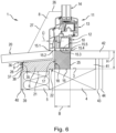
- FIG. 1 A window sill substructure 1 according to the invention is shown installed in the lower area of a building opening 2.
- the building opening 2 is a window opening. However, it can also be a door opening.
- the building opening 2 is rectangular in cross-section and closed on its four sides.
- the lower side surface 3 of the building opening 2 is formed by a crossbar 4.
- the crossbar 4 is a KVH (structural solid timber) bar, which is used, for example, in a building with a wooden construction.
- Part of the facade insulation 5 is located in front of the crossbar 4.
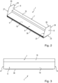
- the window sill substructure 1 essentially has four main components; the window sill support profile 6, the window support profile 7, the two side elements 8 arranged on the front sides (see also Figure 2 ) and the plaster connection profile 9.
- the window 11 is placed on the newly designed window support surface 10.
- the window 11 comprises a window frame 12 which rests on the window support profile 7, a window frame 13 which is pivotally attached to the window frame 12 for opening and closing the window 11, and the window panes 14 arranged in the window frame 13.
- the profiles for the window frame 12 and the window frame 13 are extruded plastic profiles. The structure of such windows 11 is sufficiently known and will not be explained in detail here.
- the window sill substructure 1 is intended to be used for a wide variety of window designs, as long as they are suitable for use in the respective building opening 2. It should merely be mentioned that the profiles of the window frame 12 each have a plurality of adjacent webs 15.1-15.5 with grooves in between on the peripheral sides of the window frame 12. A closed-cell sealing strip (not shown) is arranged between the window frame 12 and the window support profile 7. A similar closed-cell sealing strip (compression strip) is also located between the lateral surfaces of the building opening 2 and the correspondingly assigned mullions of the window frame 12.
- the lower transverse mullion of the window frame 12 is wider than a width B of the window support profile 7, so that it projects beyond the window support surface 10 of the window support profile 7 on both the outside and the inside, i.e., the web 15.1 is located at a distance in front of the window support profile 7 and the web 15.5 is located at a closer distance behind the window support profile 7.
- the window support profile 7 has an approximately rectangular cross-section. Due to the flat and groove-free window support surface 10, a wide variety of windows 11 can be mounted. The underside 16 of the window support profile 7 sits fully on the lower side surface 3 of the building opening 2. Typically, there is an adhesive bond between the window sill substructure 1 and the lower side surface 3 of the building opening 2.
- the window support profile 7 is made of recycled PET and is manufactured through an extrusion process. The plastic used is moisture-resistant and gives the window support profile 7 a compressive strength of approximately 1.5 MPa. The density is approximately 150 kg/m 3 . Due to these properties, the window support profile 7 is well suited for transferring the load from the window 11 to the crossbar 4.
- the window support profile 7 is provided at its base with a flat receiving recess 17 facing the window sill support profile 6, which extends approximately over half the height H (preferably between 20 mm and 35 mm) of the window support profile 7.
- the receiving recess 17 has a profile so that the window support profile 7 and the window sill support profile 6 can be connected to one another by means of a precisely fitting tongue and groove connection.
- the rear side 18 of the window sill support profile 6, which is also provided with a complementary profile, is inserted into the receiving recess 17. Due to this design, the window sill support profile 6 borders on the front side of the window support profile 7.
- window support profile 7 and the window sill support profile 6 are firmly connected, an additional adhesive and sealant is used, creating a material connection in addition to the positive fit. This creates a watertight connection between the window sill support profile 6 and the window support profile 7 over their entire length.
- the window sill support profile 6 and the window support profile 7 have the same overall length, so they are flush with each other at the end faces.
- the window sill support profile 6, which has a wedge-shaped cross-section, is made of XPS, i.e. a closed-cell insulating material, with a thermal conductivity of 0.038 W/(mK) and a density of > 30 kg/m 3 . Furthermore, the XPS has a compressive strength of approximately 300 kPa at 10% compression.
- the sloping window sill support surface 19 was smoothed by means of a thermal treatment.
- the cut-to-length end faces have also preferably been treated with a thermal process to close any open pores.
- the window sill support surface 19 serves as a second sealing level, which runs beneath a window sill 20 to be attached.
- the window sill support profile 6 has a height offset 22 on the underside 21.
- the higher part of the step is located on the lower side surface 3 of the Cross bar 4 and is thus flush with the underside 16 of the window support profile 7.
- the offset in height between the window sill support surface 19 of the window sill support profile 6 and the window support surface 10 of the window support profile 7 is 30 mm in the present case.
- the side elements 8 each consist of a thin and flexible sealing film that is cut approximately in a trapezoidal shape.
- the lower edge 23 of the side elements 8 runs flush with the underside 16 of the window support profile 7 and the associated stepped surface of the height offset 22 of the window sill support profile 6.
- the rear edge 24 of the side elements 8 runs flush with the rear vertical longitudinal end face 25 of the window support profile 7.
- the side elements 8 protrude approximately 15 cm above the window support surface 10, so that the short upper edge 26 of the side elements 8 is arranged above the lower stile of the window frame 13 and thus at the level of the window panes 14.
- the front edge 27 of the side elements 8 ends at the front upper corner of the window sill support profile 6 and then continues flush with the front side 28 of the window sill support profile 6.
- the side elements 8 are placed on the end faces of the window sill support profile 6 and the window support profile 7 and glued to them, creating a firm and watertight connection. This means that the end face of the window support profile 7 and the end face of the window sill support profile 6 are fully covered by one of the side elements 8, and the end face of the window sill support profile 6 is almost fully covered by one of the side elements 8. Only the area of the window sill support profile 6 that protrudes downwards beyond the lower side surface 3 of the crossbar 4 is not covered by a side element 8.
- the sealing film used for the side elements 8 has a nonwoven fabric base (PE) with a polyurethane coating. This makes the sealing film UV-stabilized and wind- and watertight.
- the sealing film is a tear-resistant sealing film with a tear resistance (longitudinal) of 200 N ⁇ 20 N and a tear resistance (transverse) of 185 N ⁇ 20 N (according to DIN EN 12310-1).
- the basis weight of the sealing film is 220 g/ m2 ( ⁇ 10%) (according to DIN 1849-2).
- the window sill substructure 1 has a tub shape that is open at the front, with the window sill support profile 6 forming the bottom of the tub shape, the window support profile 7 forming the rear wall of the tub shape and the two side elements 8 forming the side walls of the tub shape.
- FIG. 1 An aluminum window sill 20 is arranged on the window sill substructure 1.
- the window sill 20 has a window sill upstand 29, which is connected to the upper area of the window support profile 7 is connected, in particular screwed, to the window support profile 7.
- the central window sill area 30 runs at a parallel distance to the window sill support surface 19 and projects a few centimeters above it. Therefore, the central window sill area 30 has the same (preferably a similar) inclination as the window sill support surface 19 so that water can drain from the window sill 20 to the outside.
- thick beads of adhesive are applied to the window sill support surface 19 at a parallel distance next to one another so that parallel drainage channels are formed between the central window sill area 30 and the window sill support surface 19, through which water can drain to the front.
- a drip strip 31 which runs downwards and forms a drip nose at its free end.
- Window sill end pieces 32 are pushed onto the windowsill 20 on each side and thus form a lateral end of the windowsill.
- a gap remains between the window sill end pieces 32 and the side walls 8 so that a reveal plate (not shown) adapted to the inclined window sill support surface 19 can be placed on the window sill support profile 6.
- the window sill support profile 6 has a step 33 into which a first leg 34 of the plaster connection profile 9 is inserted.
- the upper side of the first leg 34 runs flush with the window sill support surface 19.
- a second leg 35 of the plaster connection profile 9 extends downwards and lies flush with the front side 28 of the window sill support profile 6.
- the plaster connection profile 9 has a drip strip 36 made of a rubber-elastic material that protrudes as an extension of the first leg 34.
- a reinforcing mesh 37 hangs downwards directly from the corner area between the drip strip 36 and the second leg 35. The length of the reinforcing mesh 37 is selected so that it is at least 50 mm long.
- the window sill support profile 6 Adjacent to the lower end of the second leg 35, the window sill support profile 6 has an offset step 38 on the front side 28, creating a gap of approximately 2.5 mm between the window sill support profile 6 and the reinforcing mesh 37. This ensures that the reinforcing mesh 37 is positioned approximately in the upper (front) third of a base coat of plaster 39 applied to the facade insulation 5. The finished plaster 40 is then applied to the base coat 39. The drip edge 36 is dimensioned in such a way that it protrudes outwards beyond the finished plaster 40.
- the plaster connection profile 9 is glued to the window sill support profile 6 and is thus firmly and watertightly connected to it.
- the underside 21 of the window sill support profile 76 has a width that is precisely adapted to the thickness of the facade insulation 5. In this respect, a secure connection of this element of the window sill substructure 1 to the facade insulation 5 is also possible.
- the drip strip 36 is shorter than the rest of the plaster connection profile 9.
- the remaining distance between the drip strip 36 and the side elements 8 essentially corresponds to a reveal panel that is still to be attached and which abuts the window frame 12 on the front with a seal interposed.
- the outward-facing side surfaces of the side elements 8 are connected, preferably glued, both to the side surfaces of the building opening 2 and to any facade insulation present there.
- a sealing tape inserted laterally between the vertical beams of the window frame 12 extends from the window support profile 7, initially upwards along a side element 8, and then rests directly against a side surface of the building opening 2 above the upper edge 26 of the side element 8. Due to the relatively small thickness of the side element 8, the sealing tape easily compensates for the thickness.
- an inner window sill 42 On the inside of the building, on the lower side surface 3, directly adjacent to the window sill substructure 1, there is a filler piece 41 and an inner window sill 42 arranged thereon. Furthermore, underneath the inner window sill 42 there is an inner panel 43 (e.g. a wooden panel) and a further inner panel 44 (e.g. a plasterboard) arranged above it.
- an inner panel 43 e.g. a wooden panel
- a further inner panel 44 e.g. a plasterboard
- the window sill substructure 1 described in detail above simplifies the sealed arrangement of a window sill 20 and a window 11 in a building opening 2. Due to the formed watertight tub shape, an automatically sealed insulation is created while simultaneously forming a second sealing level under the window sill 20.
- the already prefabricated and prepared window sill substructure 1, as in Figures 2 and 3 As shown, they are placed on the crossbar 4 of a building opening 2 and the facade insulation 5 and firmly connected to them. Due to their flexibility, the side elements 8 can be pressed laterally and glued to both the building opening 2 and the facade insulation 5. Window 11 is then installed with the appropriate sealing tapes interposed. Then the side reveal panels are inserted. Finally, the plastering is applied.
- the window sill substructure 1 can be manufactured in different lengths and widths.
- the window support profile 7 has been designed to be suitable for a wide variety of windows 11 available on the market.
- the weight of the window 11 is optimally transferred to the crossbar 4 by means of the window support profile 7.
- excellent Insulation in the area of the window sill 20 and the provision of a second sealing layer Due to the materials selected for the individual elements of the window sill substructure 1 and the watertight connection of the elements to one another, a good seal is inevitably achieved in the lower corner area of the building opening 2.
- a block-shaped supplementary element 45 is arranged in the corner area between the window sill support profile 6, the window support profile 7, and a side element 8.
- the supplementary element 45 is glued to all three elements and sits on the window sill support profile 6. For this purpose, it is beveled at the bottom according to the inclination of the window sill support surface 19.
- the height H E of the supplementary element 45 corresponds to the height by which the window support profile 7 projects above the window sill support profile 6.
- the thickness D E of the supplementary element 45 corresponds to the projection Ü (see Figure 1 ), which the window frame 12 placed on the window support profile 7 protrudes forwards over the window support profile 7. As a result, the supplementary element 45 is flush with the outside of the window frame 12.
- the width B E of the supplementary element 45 corresponds to the width of a reveal panel (not shown) to be placed on the window sill support profile 6.
- the sealing in this area can be further improved by the supplementary element 50.
- the Figures 4 and 5 The window sill substructure 1 shown can be installed in the same way as the one shown in Figure 1 shown variant can be inserted into the same building opening 2.
Landscapes
- Engineering & Computer Science (AREA)
- Civil Engineering (AREA)
- Structural Engineering (AREA)
- Specific Sealing Or Ventilating Devices For Doors And Windows (AREA)
Applications Claiming Priority (1)
| Application Number | Priority Date | Filing Date | Title |
|---|---|---|---|
| DE202023105408.0U DE202023105408U1 (de) | 2023-09-18 | 2023-09-18 | Unterbauwanne mit Kombinationswerkstoffen |
Publications (1)
| Publication Number | Publication Date |
|---|---|
| EP4524355A1 true EP4524355A1 (fr) | 2025-03-19 |
Family
ID=92791883
Family Applications (1)
| Application Number | Title | Priority Date | Filing Date |
|---|---|---|---|
| EP24199909.3A Pending EP4524355A1 (fr) | 2023-09-18 | 2024-09-12 | Cuve de dessous de caisse à matériaux composites |
Country Status (2)
| Country | Link |
|---|---|
| EP (1) | EP4524355A1 (fr) |
| DE (1) | DE202023105408U1 (fr) |
Citations (9)
| Publication number | Priority date | Publication date | Assignee | Title |
|---|---|---|---|---|
| US20070266663A1 (en) | 2004-04-28 | 2007-11-22 | Hopkins John R | Door and window sill gasket |
| DE102012212551A1 (de) | 2012-07-18 | 2014-01-23 | Kunststoffwerk Katzbach Gmbh & Co. Kg | Dämmplatte für Fensterlaibungen |
| DE202014008247U1 (de) | 2014-10-15 | 2016-01-18 | D & M Rolladentechnik Gmbh | Abdichtungsvorrichtung zur Abdichtung eines Fensterrahmens im unteren Bereich einer Wandöffnung |
| DE202016101812U1 (de) * | 2015-04-21 | 2016-05-11 | Fe System Fassaden Gmbh | Fenster |
| DE202017101034U1 (de) | 2017-02-24 | 2018-02-14 | Kunststoffwerk Katzbach Gmbh & Co. Kg | Fensterbank-Montageelement |
| DE202017006577U1 (de) | 2017-12-19 | 2019-03-20 | Pflüger TOB GmbH | Seitenelement |
| DE202019104202U1 (de) | 2018-08-06 | 2019-09-04 | Fe System Fassaden Gmbh | Fenster |
| US20200270932A1 (en) | 2019-02-23 | 2020-08-27 | Gregory A Header | Continuous Sill for Doors with Sidelites |
| DE102019220617A1 (de) * | 2019-12-30 | 2021-07-01 | Baywa Aktiengesellschaft | Montageeinheit |
-
2023
- 2023-09-18 DE DE202023105408.0U patent/DE202023105408U1/de active Active
-
2024
- 2024-09-12 EP EP24199909.3A patent/EP4524355A1/fr active Pending
Patent Citations (9)
| Publication number | Priority date | Publication date | Assignee | Title |
|---|---|---|---|---|
| US20070266663A1 (en) | 2004-04-28 | 2007-11-22 | Hopkins John R | Door and window sill gasket |
| DE102012212551A1 (de) | 2012-07-18 | 2014-01-23 | Kunststoffwerk Katzbach Gmbh & Co. Kg | Dämmplatte für Fensterlaibungen |
| DE202014008247U1 (de) | 2014-10-15 | 2016-01-18 | D & M Rolladentechnik Gmbh | Abdichtungsvorrichtung zur Abdichtung eines Fensterrahmens im unteren Bereich einer Wandöffnung |
| DE202016101812U1 (de) * | 2015-04-21 | 2016-05-11 | Fe System Fassaden Gmbh | Fenster |
| DE202017101034U1 (de) | 2017-02-24 | 2018-02-14 | Kunststoffwerk Katzbach Gmbh & Co. Kg | Fensterbank-Montageelement |
| DE202017006577U1 (de) | 2017-12-19 | 2019-03-20 | Pflüger TOB GmbH | Seitenelement |
| DE202019104202U1 (de) | 2018-08-06 | 2019-09-04 | Fe System Fassaden Gmbh | Fenster |
| US20200270932A1 (en) | 2019-02-23 | 2020-08-27 | Gregory A Header | Continuous Sill for Doors with Sidelites |
| DE102019220617A1 (de) * | 2019-12-30 | 2021-07-01 | Baywa Aktiengesellschaft | Montageeinheit |
Non-Patent Citations (1)
| Title |
|---|
| HECHENBLAICKNER: "PET-Leichtbauplatte", 31 March 2022 (2022-03-31), pages 1 - 6, XP093241588, Retrieved from the Internet <URL:https://www.heholz.at/content/5-downloads/2-prospekte/pet-recyclingplatte.pdf> [retrieved on 20250121] * |
Also Published As
| Publication number | Publication date |
|---|---|
| DE202023105408U1 (de) | 2024-09-20 |
Similar Documents
| Publication | Publication Date | Title |
|---|---|---|
| EP0162227B2 (fr) | Façade ou couverture du type métal-vitre | |
| DE2939730A1 (de) | Dachlatte | |
| EP3663497B1 (fr) | Dispositif d'étanchéification d'un cadre de fenêtre dans la zone infèrieure d'une ouverture de paroi | |
| EP2642060B1 (fr) | Battant de fenêtre ou de porte | |
| EP2434082B1 (fr) | Panneau de rebord de fenêtre | |
| EP2853653B1 (fr) | Bande | |
| AT508293B1 (de) | Formteil zur wärmedämmung einer leibung in einer wandöffnung | |
| AT14747U1 (de) | Fenster | |
| CH706561B1 (de) | Fenster- oder Türflügel. | |
| EP3009577B1 (fr) | Bande d'etancheite | |
| EP1780348A2 (fr) | Élément préfabriqué pour fabrication d'un élément de construction | |
| EP0198157B1 (fr) | Liste d'un joint de dilatation en matière plastique, spécialement pour le joint de bordure d'une construction de plancher | |
| DE102007054369B4 (de) | Zarge für den Einbau eines Fensters oder einer Tür | |
| EP2708674B1 (fr) | Bande de crépissage et baguette d'angle pour enduit | |
| EP4524355A1 (fr) | Cuve de dessous de caisse à matériaux composites | |
| DE102020131475A1 (de) | Wassertasse für eine Fensterbank sowie Fenstersystem mit einer solchen Wassertasse | |
| DE20307556U1 (de) | Leiste | |
| DE9303937U1 (de) | Sanitaerkabine | |
| EP0495150B1 (fr) | Construction de façade | |
| DE202011100460U1 (de) | Wandaufbau mit Fensterbankformteil | |
| DE202024105724U1 (de) | Kombiniertes Dämm- und Dichtelement zur Abdichtung eines Tür- oder Fensterrahmens im unteren Eckbereich einer Gebäudeöffnung | |
| DE20009185U1 (de) | Schwellenprofil für Gebäudetüren sowie Gebäudetür | |
| EP3118388A1 (fr) | Baguette en plastique et plinthe en plastique à embout isolant et méthode pour produire la baguette | |
| EP1327731A1 (fr) | Façade | |
| EP3115526A1 (fr) | Étanchéification de joints entre des éléments d'isolation destinés à l'isolation de bâtiment |
Legal Events
| Date | Code | Title | Description |
|---|---|---|---|
| PUAI | Public reference made under article 153(3) epc to a published international application that has entered the european phase |
Free format text: ORIGINAL CODE: 0009012 |
|
| STAA | Information on the status of an ep patent application or granted ep patent |
Free format text: STATUS: THE APPLICATION HAS BEEN PUBLISHED |
|
| AK | Designated contracting states |
Kind code of ref document: A1 Designated state(s): AL AT BE BG CH CY CZ DE DK EE ES FI FR GB GR HR HU IE IS IT LI LT LU LV MC ME MK MT NL NO PL PT RO RS SE SI SK SM TR |
|
| STAA | Information on the status of an ep patent application or granted ep patent |
Free format text: STATUS: REQUEST FOR EXAMINATION WAS MADE |
|
| 17P | Request for examination filed |
Effective date: 20250521 |
|
| STAA | Information on the status of an ep patent application or granted ep patent |
Free format text: STATUS: EXAMINATION IS IN PROGRESS |
|
| 17Q | First examination report despatched |
Effective date: 20250717 |