EP4524372A1 - Stator à hauteur radiale réglable - Google Patents
Stator à hauteur radiale réglable Download PDFInfo
- Publication number
- EP4524372A1 EP4524372A1 EP24188689.4A EP24188689A EP4524372A1 EP 4524372 A1 EP4524372 A1 EP 4524372A1 EP 24188689 A EP24188689 A EP 24188689A EP 4524372 A1 EP4524372 A1 EP 4524372A1
- Authority
- EP
- European Patent Office
- Prior art keywords
- radial
- stator
- nut
- primary clearance
- clearance
- Prior art date
- Legal status (The legal status is an assumption and is not a legal conclusion. Google has not performed a legal analysis and makes no representation as to the accuracy of the status listed.)
- Pending
Links
Images


Classifications
-
- F—MECHANICAL ENGINEERING; LIGHTING; HEATING; WEAPONS; BLASTING
- F01—MACHINES OR ENGINES IN GENERAL; ENGINE PLANTS IN GENERAL; STEAM ENGINES
- F01D—NON-POSITIVE DISPLACEMENT MACHINES OR ENGINES, e.g. STEAM TURBINES
- F01D11/00—Preventing or minimising internal leakage of working-fluid, e.g. between stages
- F01D11/02—Preventing or minimising internal leakage of working-fluid, e.g. between stages by non-contact sealings, e.g. of labyrinth type
- F01D11/025—Seal clearance control; Floating assembly; Adaptation means to differential thermal dilatations
-
- F—MECHANICAL ENGINEERING; LIGHTING; HEATING; WEAPONS; BLASTING
- F01—MACHINES OR ENGINES IN GENERAL; ENGINE PLANTS IN GENERAL; STEAM ENGINES
- F01D—NON-POSITIVE DISPLACEMENT MACHINES OR ENGINES, e.g. STEAM TURBINES
- F01D11/00—Preventing or minimising internal leakage of working-fluid, e.g. between stages
- F01D11/08—Preventing or minimising internal leakage of working-fluid, e.g. between stages for sealing space between rotor blade tips and stator
- F01D11/14—Adjusting or regulating tip-clearance, i.e. distance between rotor-blade tips and stator casing
- F01D11/20—Actively adjusting tip-clearance
- F01D11/22—Actively adjusting tip-clearance by mechanically actuating the stator or rotor components, e.g. moving shroud sections relative to the rotor
-
- F—MECHANICAL ENGINEERING; LIGHTING; HEATING; WEAPONS; BLASTING
- F01—MACHINES OR ENGINES IN GENERAL; ENGINE PLANTS IN GENERAL; STEAM ENGINES
- F01D—NON-POSITIVE DISPLACEMENT MACHINES OR ENGINES, e.g. STEAM TURBINES
- F01D11/00—Preventing or minimising internal leakage of working-fluid, e.g. between stages
- F01D11/001—Preventing or minimising internal leakage of working-fluid, e.g. between stages for sealing space between stator blade and rotor
-
- F—MECHANICAL ENGINEERING; LIGHTING; HEATING; WEAPONS; BLASTING
- F01—MACHINES OR ENGINES IN GENERAL; ENGINE PLANTS IN GENERAL; STEAM ENGINES
- F01D—NON-POSITIVE DISPLACEMENT MACHINES OR ENGINES, e.g. STEAM TURBINES
- F01D11/00—Preventing or minimising internal leakage of working-fluid, e.g. between stages
- F01D11/08—Preventing or minimising internal leakage of working-fluid, e.g. between stages for sealing space between rotor blade tips and stator
- F01D11/14—Adjusting or regulating tip-clearance, i.e. distance between rotor-blade tips and stator casing
- F01D11/20—Actively adjusting tip-clearance
-
- F—MECHANICAL ENGINEERING; LIGHTING; HEATING; WEAPONS; BLASTING
- F01—MACHINES OR ENGINES IN GENERAL; ENGINE PLANTS IN GENERAL; STEAM ENGINES
- F01D—NON-POSITIVE DISPLACEMENT MACHINES OR ENGINES, e.g. STEAM TURBINES
- F01D17/00—Regulating or controlling by varying flow
- F01D17/02—Arrangement of sensing elements
-
- F—MECHANICAL ENGINEERING; LIGHTING; HEATING; WEAPONS; BLASTING
- F01—MACHINES OR ENGINES IN GENERAL; ENGINE PLANTS IN GENERAL; STEAM ENGINES
- F01D—NON-POSITIVE DISPLACEMENT MACHINES OR ENGINES, e.g. STEAM TURBINES
- F01D25/00—Component parts, details, or accessories, not provided for in, or of interest apart from, other groups
- F01D25/24—Casings; Casing parts, e.g. diaphragms, casing fastenings
- F01D25/246—Fastening of diaphragms or stator-rings
-
- F—MECHANICAL ENGINEERING; LIGHTING; HEATING; WEAPONS; BLASTING
- F01—MACHINES OR ENGINES IN GENERAL; ENGINE PLANTS IN GENERAL; STEAM ENGINES
- F01D—NON-POSITIVE DISPLACEMENT MACHINES OR ENGINES, e.g. STEAM TURBINES
- F01D9/00—Stators
- F01D9/02—Nozzles; Nozzle boxes; Stator blades; Guide conduits, e.g. individual nozzles
- F01D9/04—Nozzles; Nozzle boxes; Stator blades; Guide conduits, e.g. individual nozzles forming ring or sector
- F01D9/042—Nozzles; Nozzle boxes; Stator blades; Guide conduits, e.g. individual nozzles forming ring or sector fixing blades to stators
- F01D9/044—Nozzles; Nozzle boxes; Stator blades; Guide conduits, e.g. individual nozzles forming ring or sector fixing blades to stators permanently, e.g. by welding, brazing, casting or the like
-
- F—MECHANICAL ENGINEERING; LIGHTING; HEATING; WEAPONS; BLASTING
- F04—POSITIVE - DISPLACEMENT MACHINES FOR LIQUIDS; PUMPS FOR LIQUIDS OR ELASTIC FLUIDS
- F04D—NON-POSITIVE-DISPLACEMENT PUMPS
- F04D29/00—Details, component parts, or accessories
- F04D29/60—Mounting; Assembling; Disassembling
- F04D29/64—Mounting; Assembling; Disassembling of axial pumps
- F04D29/644—Mounting; Assembling; Disassembling of axial pumps especially adapted for elastic fluid pumps
-
- F—MECHANICAL ENGINEERING; LIGHTING; HEATING; WEAPONS; BLASTING
- F05—INDEXING SCHEMES RELATING TO ENGINES OR PUMPS IN VARIOUS SUBCLASSES OF CLASSES F01-F04
- F05D—INDEXING SCHEME FOR ASPECTS RELATING TO NON-POSITIVE-DISPLACEMENT MACHINES OR ENGINES, GAS-TURBINES OR JET-PROPULSION PLANTS
- F05D2230/00—Manufacture
- F05D2230/60—Assembly methods
- F05D2230/64—Assembly methods using positioning or alignment devices for aligning or centring, e.g. pins
- F05D2230/644—Assembly methods using positioning or alignment devices for aligning or centring, e.g. pins for adjusting the position or the alignment, e.g. wedges or eccenters
-
- F—MECHANICAL ENGINEERING; LIGHTING; HEATING; WEAPONS; BLASTING
- F05—INDEXING SCHEMES RELATING TO ENGINES OR PUMPS IN VARIOUS SUBCLASSES OF CLASSES F01-F04
- F05D—INDEXING SCHEME FOR ASPECTS RELATING TO NON-POSITIVE-DISPLACEMENT MACHINES OR ENGINES, GAS-TURBINES OR JET-PROPULSION PLANTS
- F05D2240/00—Components
- F05D2240/10—Stators
- F05D2240/11—Shroud seal segments
-
- F—MECHANICAL ENGINEERING; LIGHTING; HEATING; WEAPONS; BLASTING
- F05—INDEXING SCHEMES RELATING TO ENGINES OR PUMPS IN VARIOUS SUBCLASSES OF CLASSES F01-F04
- F05D—INDEXING SCHEME FOR ASPECTS RELATING TO NON-POSITIVE-DISPLACEMENT MACHINES OR ENGINES, GAS-TURBINES OR JET-PROPULSION PLANTS
- F05D2270/00—Control
- F05D2270/40—Type of control system
- F05D2270/44—Type of control system active, predictive, or anticipative
-
- F—MECHANICAL ENGINEERING; LIGHTING; HEATING; WEAPONS; BLASTING
- F05—INDEXING SCHEMES RELATING TO ENGINES OR PUMPS IN VARIOUS SUBCLASSES OF CLASSES F01-F04
- F05D—INDEXING SCHEME FOR ASPECTS RELATING TO NON-POSITIVE-DISPLACEMENT MACHINES OR ENGINES, GAS-TURBINES OR JET-PROPULSION PLANTS
- F05D2270/00—Control
- F05D2270/80—Devices generating input signals, e.g. transducers, sensors, cameras or strain gauges
-
- F—MECHANICAL ENGINEERING; LIGHTING; HEATING; WEAPONS; BLASTING
- F05—INDEXING SCHEMES RELATING TO ENGINES OR PUMPS IN VARIOUS SUBCLASSES OF CLASSES F01-F04
- F05D—INDEXING SCHEME FOR ASPECTS RELATING TO NON-POSITIVE-DISPLACEMENT MACHINES OR ENGINES, GAS-TURBINES OR JET-PROPULSION PLANTS
- F05D2270/00—Control
- F05D2270/80—Devices generating input signals, e.g. transducers, sensors, cameras or strain gauges
- F05D2270/821—Displacement measuring means, e.g. inductive
Definitions
- the present invention relates to turbine engines, stator assemblies and, in one embodiment, to a stator with adjustable radial heights and method for adjusting its height.
- a gas turbine engine air is compressed in a compressor and compressor air is then mixed with fuel and combusted in a combustor to produce a high-temperture and high-pressure working fluid.
- This working fluid is directed into a turbine in which the working fluid is expanded to generate power.
- the generated power drives the rotation of a rotor within the turbine through aerodynamic interactions between the working fluid and turbine blades or airfoils.
- the rotor can be used to drive rotations of a propeller or to produce electricity in a generator.
- a stator is a component of the gas turbine engine that remains stationary while the rotor rotates about a rotational axis relative to the stator.
- multiple stators of different radial heights are needed for knife edge clearance tests. These tests require that the stators be repeatedly replaced by disassembly and reassembly of cases and mating parts. Such disassembling and reassembling of components during tests may cause significant noise in measurements.
- a stator assembly includes a stator element and a radial height adjustment mechanism (e.g., a radial position or radial clearance adjustment mechanism).
- the stator assembly includes an inboard portion which establishes a primary clearance with rotor elements and exhibits a measurable parameter corresponding to the primary clearance and an outboard portion integrally formed with the inboard portion.
- the radial height adjustment mechanism is coupled with the outboard portion and configured to be operable, based on the measurable parameter, to adjust a radial height (e.g., a radial position or a radial clearance from rotor elements) of the stator element and in turn to adjust the primary clearance.
- the measurable parameter may be a capacitance
- the stator element may include a body including an inner stator wall forming the inboard portion, an outer stator wall forming the outboard portion and stator vanes radially interposed between the inner stator wall and the outer stator wall.
- the radial height adjustment mechanism may include a radial shaft affixed to the outboard portion and including a shoulder.
- a nut which may be threadably engaged with the radial shaft whereby rotation of the nut adjusts a radial position of the stator element and the primary clearance and adjusts a secondary clearance and a shim to set the secondary clearance and in turn to set the radial position of the stator element and the primary clearance.
- the radial height adjustment mechanism may include a radial shaft threadably engaged with the outboard portion and a nut which is affixed to the radial shaft, whereby rotation of the nut rotates the radial shaft and radial shaft rotation adjusts (e.g. securably adjusts) a radial position of the stator element and the primary clearance.
- the radial height adjustment mechanism may include an internal radial shaft that abuts with the outboard portion, an external radial shaft that surrounds the internal radial shaft and includes a shoulder and a first dovetail which is engagable with a second dovetail of the outboard portion, a nut which is threadably engaged with the external radial shaft, whereby rotation of the nut causes engagement of the first and second dovetails to thereby adjust a radial position of the stator element and the primary clearance and adjusts a secondary clearance and a shim to set the secondary clearance and in turn to set the radial position of the stator element and the primary clearance.
- the radial height adjustment mechanism may include a radial shaft affixed to the outboard portion, a bridge through which the radial shaft extends and a nut combination, which is threadably engaged with the radial shaft, whereby operation of the nut combination adjusts (e.g. securably adjusts) a radial position of the stator element relative to the bridge and the primary clearance.
- a turbine engine includes rotor elements and a case disposed about the rotor elements and including a stator assembly (e.g., the stator assembly of any of the aspects or embodiments described above and herein).
- the stator assembly includes a stator element and a radial height adjustment mechanism (e.g., a radial position or radial clearance adjustment mechanism).
- the stator element includes an inboard portion which establishes a primary clearance with the rotor elements and exhibits a measurable parameter corresponding to the primary clearance and an outboard portion integrally formed with the inboard portion.
- the radial height adjustment mechanism is coupled with the outboard portion and configured to be operable, based on the measurable parameter, to adjust a radial height (e.g., a radial position or a radial clearance) of the stator element and in turn to adjust the primary clearance between the inboard portion and the rotor elements.
- a radial height e.g., a radial position or a radial clearance
- the rotor elements may include knife edges.
- the measurable parameter may be a capacitance of the inboard portion and the rotor elements across the primary clearance.
- the stator element may include a body having the inboard portion at an inboard side thereof and the outboard portion at an outboard side thereof.
- the body may include an inner stator wall forming the inboard portion, an outer stator wall forming the outboard portion and which is disposable in close proximity to an internal wall of the case and stator vanes radially interposed between the inner stator wall and the outer stator wall.
- the radial height adjustment mechanism may include a radial shaft affixed to the outboard portion and including a shoulder, a nut which is threadably engaged with a boss formed on the case and with the radial shaft whereby rotation of the nut adjusts a radial position of the stator element and the primary clearance and adjusts a secondary clearance between the shoulder and the boss.
- the radial height adjustment mechanism may include a shim interposed between the shoulder and the boss to set the secondary clearance and in turn to set the radial position of the stator element and the primary clearance.
- the radial height adjustment mechanism may include a radial shaft threadably engaged with the outboard portion and a nut which is threadably engaged with a boss formed on the case and which is affixed to the radial shaft whereby rotation of the nut rotates the radial shaft and radial shaft rotation adjusts (e.g. securably adjusts) a radial position of the stator element and the primary clearance.
- the radial height adjustment mechanism may include an internal radial shaft that abuts with the outboard portion, an external radial shaft that surrounds the internal radial shaft and includes a shoulder and a first dovetail which is engagable with a second dovetail of the outboard portion, a nut which is threadably engaged with a boss formed on the case and with the external radial shaft whereby rotation of the nut causes engagement of the first and second dovetails to thereby adjust a radial position of the stator element and the primary clearance and adjusts a secondary clearance between the shoulder and the boss.
- the radial height adjustment mechanism may include a shim interposed between the shoulder and the boss to set the secondary clearance and in turn to set the radial position of the stator element and the primary clearance.
- the radial height adjustment mechanism may include a radial shaft affixed to the outboard portion, a bridge anchored on the case and through which the radial shaft extends and a nut combination, which is threadably engaged with the radial shaft, whereby operation of the nut combination adjusts (e.g. securably adjusts) a radial position of the stator element relative to the bridge and the primary clearance.
- a method of adjusting a height of a stator element includes measuring a parameter between an inboard portion of the stator element and rotor elements, determining a primary clearance, with which the parameter corresponds, between the inboard portion and the rotor elements based on results of the measuring (e.g., based on the measured parameter), operating a radial height adjustment mechanism (e.g., a radial position or radial clearance adjustment mechanism), which is coupled with an outboard portion of the stator element, to adjust a radial height (e.g., a radial position or a radial clearance) of the stator element and to thereby adjust the primary clearance and iteratively repeating the measuring, the determining and the operating toward the primary clearance being within predefined limits.
- a radial height adjustment mechanism e.g., a radial position or a radial clearance
- the parameter may include a capacitance of the inboard portion and the rotor elements across the primary clearance.
- the stator element may include a body having the inboard portion at an inboard side thereof and the outboard portion at an outboard side thereof and the body includes an inner stator wall forming the inboard portion, an outer stator wall forming the outboard portion and stator vanes radially interposed between the inner stator wall and the outer stator wall.
- the rotor elements may include knife edges.
- the operating of the radial height adjustment mechanism may adjust a radial height (e.g., a radial position or a radial clearance) of the stator element relative to a case of a turbine engine.
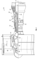
- FIG. 1 schematically illustrates a gas turbine engine 20.
- the gas turbine engine 20 is disclosed herein as a two-spool turbofan that generally incorporates a fan section 22, a compressor section 24, a combustor section 26 and a turbine section 28.
- Alternative engines might include other systems or features.
- the fan section 22 drives air along a bypass flow path B in a bypass duct, while the compressor section 24 drives air along a core flow path C for compression and communication into the combustor section 26 and then expansion through the turbine section 28.
- the exemplary gas turbine engine 20 generally includes a low speed spool 30 and a high speed spool 32 mounted for rotation about an engine central longitudinal axis A relative to an engine static structure 36 via several bearing systems 38. It should be understood that various bearing systems 38 at various locations may alternatively or additionally be provided, and the location of bearing systems 38 may be varied as appropriate to the application.
- the low speed spool 30 generally includes an inner shaft 40 that interconnects a fan 42, a low pressure compressor 44 and a low pressure turbine 46.
- the inner shaft 40 is connected to the fan 42 through a speed change mechanism, which in exemplary gas turbine engine 20 is illustrated as a geared architecture 48 to drive the fan 42 at a lower speed than the low speed spool 30.
- the high speed spool 32 includes an outer shaft 50 that interconnects a high pressure compressor 52 and high pressure turbine 54.
- a combustor 56 is arranged in the gas turbine engine 20 between the high pressure compressor 52 and the high pressure turbine 54.
- the engine static structure 36 is arranged generally between the high pressure turbine 54 and the low pressure turbine 46.
- the engine static structure 36 further supports the bearing systems 38 in the turbine section 28.
- the inner shaft 40 and the outer shaft 50 are concentric and rotate via bearing systems 38 about the engine central longitudinal axis A which is collinear with their longitudinal axes.
- the core airflow is compressed by the low pressure compressor 44 and then the high pressure compressor 52, is mixed and burned with fuel in the combustor 56 and is then expanded over the high pressure turbine 54 and the low pressure turbine 46.
- the high and low pressure turbines 54 and 46 rotationally drive the low speed spool 30 and the high speed spool 32, respectively, in response to the expansion.
- geared architecture 48 may be located aft of the combustor section 26 or even aft of the turbine section 28, and the fan section 22 may be positioned forward or aft of the location of geared architecture 48.
- a stator is provided with a mechanism for adjusting a radial height thereof. This allows the stator to be used at various radial locations around a case without requiring disassembly, replacement and reassembly of components.
- a stator assembly 301 is provided for a case 302 of a turbine engine, such as the gas turbine engine 20 of FIG. 1 , which is disposed about rotor elements 303.
- the rotor elements 303 can be provided as knife edges 3030.
- the stator assembly 301 includes a stator element 310 and a radial height adjustment mechanism 330.
- the stator element 310 includes an inboard portion 311 and an outboard portion 312.
- the inboard portion 311 establishes a primary clearance C with the rotor elements 303 and exhibits a measurable parameter corresponding to the primary clearance C.
- the measurable parameter can be a capacitance between the inboard portion 311 and the rotor elements 303 across the primary clearance C.
- the outboard portion 312 is integrally formed with the inboard portion 311 as will be discussed below such that, as a radial height or position of the outboard portion 312 is adjusted or changes, a radial height or position of the inboard portion 311 is correspondingly adjusted or changes (and thus the measurable parameter, i.e., the capacitance, is adjusted or changes).
- the radial height adjustment mechanism 330 is coupled with the outboard portion 312 and configured to be operable, based on the measurable parameter, to adjust a radial height of the stator element 310 relative to the case 302 and the rotor elements 303 and in turn to adjust the primary clearance C between the inboard portion 311 and the rotor elements 303.
- the stator element 310 further includes a body 313 having the inboard portion 311 at an inboard side 313 1 thereof and the outboard portion 312 at an outboard side 312 1 thereof.
- the body 313 can be generally rigid and includes an inner stator wall 314 forming the inboard portion 311, an outer stator wall 315 forming the outboard portion 312 and which is disposable in close proximity to an internal wall 304 of the case 302 and stator vanes 316 which are radially interposed between the inner stator wall 314 and the outer stator wall 315.
- the radial height adjustment mechanism 330 can include a partially threaded radial shaft 340, which is affixed to the outboard portion 312, a bridge 341 that is anchored on an exterior surface of the case 302 and through which the radial shaft 340 extends and a nut combination 342.
- the nut combination 342 can include a fixing nut which is abuttable with an exterior surface of the bridge 341, an adjusting nut which is adjustable to adjust a height of the radial shaft 340 and a jam nut which holds the adjustable in place in abutment with an interior surface of the bridge 341.
- the nut combination 342 is thus threadably engaged with the radial shaft 340 whereby operation of the nut combination 342 securably adjusts a radial position of the stator element 310 relative to the bridge 341, the case 302 and the rotor elements 303 and in turn securably adjusts the primary clearance C (see FIG. 2 ).
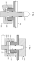
- the radial height adjustment mechanism 330 can include a radial shaft 410 that is affixed to the outboard portion 312 and includes a shoulder 411, a nut 420 and a shim 430.
- the nut 420 is threadably engaged with a boss 421 formed on the case 302 and with the radial shaft 410. Rotation of the nut 420 adjusts a radial position of the stator element 310 relative to the case 302 and the rotor elements 303 (see FIG. 2 ) and the primary clearance C (see FIG. 2 ) and also adjusts a secondary clearance C2 between the shoulder 411 and the boss 421.
- the shim 430 is interposable between the shoulder 411 and the boss 421 to set the secondary clearance C2 and in turn to set the radial position of the stator element 310 and the primary clearance C.
- the radial height adjustment mechanism 330 can include a radial shaft 510 threadably engaged with the outboard portion 312 and a nut 520.
- the nut 520 is threadably engaged with a boss 521 formed on the case 302 (see FIG. 2 ) and is affixed to the radial shaft 510. Rotation of the nut 520 rotates the radial shaft 510 and radial shaft 510 rotation securably adjusts a radial position of the stator element 310 relative to the case 302 and the rotor elements 303 and the primary clearance C.
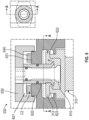
- the radial height adjustment mechanism 330 includes an internal radial shaft 610 that abuts with the outboard portion 312, an external radial shaft 620 that surrounds the internal radial shaft 610 and includes a shoulder 621 and a first dovetail 622.
- the first dovetail 622 is engagable with a second dovetail 623 of the outboard portion 312.
- the radial height adjustment mechanism 330 further includes a nut 630 and a shim 640.
- the nut 630 is threadably engaged with a boss 631 formed on the case 302 (see FIG. 2 ) and with the external radial shaft 620.
- Rotation of the nut 630 causes engagement of the first and second dovetails 622 and 623 to thereby adjust a radial position of the stator element 310 relative to the case 302 and the rotor elements 303 and the primary clearance C and adjusts a secondary clearance C2 between the shoulder 621 and the boss 631.
- the shim 640 is interposable between the shoulder 621 and the boss 631 to set the secondary clearance C2 and in turn to set the radial position of the stator element 310 relatively to the case 302 and the rotor elements 303 and the primary clearance C.
- the method includes measuring a parameter (i.e., a capacitance) between an inboard portion of the stator element and rotor elements (block 701), determining a primary clearance, with which the parameter corresponds, between the inboard portion and the rotor elements (i.e., knife edges) based on results of the measuring (block 702), operating a radial height adjustment mechanism, which is coupled with an outboard portion of the stator element, to adjust a radial height of the stator element relative to a case of a turbine engine and to thereby adjust the primary clearance (block 703) and iteratively repeating the measuring, the determining and the operating toward the primary clearance being within predefined limits (block 704).
- a parameter i.e., a capacitance
- Benefits of the features described herein are the provision of a stator with an adjustable radial height that minimizes manufacturing efforts, increases measurement confidence without measurement noise caused by disassembly and reassembly of components and minimizes potential damage to instrumentation cables, hypo tubes and egress seals.
Landscapes
- Engineering & Computer Science (AREA)
- Mechanical Engineering (AREA)
- General Engineering & Computer Science (AREA)
- Structures Of Non-Positive Displacement Pumps (AREA)
- Chemical & Material Sciences (AREA)
- Combustion & Propulsion (AREA)
Applications Claiming Priority (1)
| Application Number | Priority Date | Filing Date | Title |
|---|---|---|---|
| US18/467,837 US20250092821A1 (en) | 2023-09-15 | 2023-09-15 | Stator with adjustable radial height |
Publications (1)
| Publication Number | Publication Date |
|---|---|
| EP4524372A1 true EP4524372A1 (fr) | 2025-03-19 |
Family
ID=91950277
Family Applications (1)
| Application Number | Title | Priority Date | Filing Date |
|---|---|---|---|
| EP24188689.4A Pending EP4524372A1 (fr) | 2023-09-15 | 2024-07-15 | Stator à hauteur radiale réglable |
Country Status (2)
| Country | Link |
|---|---|
| US (1) | US20250092821A1 (fr) |
| EP (1) | EP4524372A1 (fr) |
Citations (5)
| Publication number | Priority date | Publication date | Assignee | Title |
|---|---|---|---|---|
| CA2021102A1 (fr) * | 1989-09-08 | 1991-03-09 | John J. Ciokajlo | Dispositif de reglage du jeu a l'extremite des pales d'une turbine a gaz |
| EP3287606A1 (fr) * | 2016-08-04 | 2018-02-28 | United Technologies Corporation | Joint d'air extérieur d'aube réglable |
| EP2815082B1 (fr) * | 2012-02-14 | 2019-02-13 | United Technologies Corporation | Appareil d'étanchéité à l'air externe à lames réglables |
| EP3584531A2 (fr) * | 2018-06-19 | 2019-12-25 | United Technologies Corporation | Systèmes et procédés pour des ensembles de sonde de capacité pseudo-triaxiale |
| EP3097274B1 (fr) * | 2013-12-30 | 2021-05-19 | Raytheon Technologies Corporation | Système de réduction des jeux de l'extrémité d'une aube à réponse rapide accessible |
Family Cites Families (2)
| Publication number | Priority date | Publication date | Assignee | Title |
|---|---|---|---|---|
| US4710097A (en) * | 1986-05-27 | 1987-12-01 | Avco Corporation | Stator assembly for gas turbine engine |
| FR3083564B1 (fr) * | 2018-07-05 | 2021-07-09 | Safran Aircraft Engines | Turbine comportant un element abradable a position radiale ajustable |
-
2023
- 2023-09-15 US US18/467,837 patent/US20250092821A1/en active Pending
-
2024
- 2024-07-15 EP EP24188689.4A patent/EP4524372A1/fr active Pending
Patent Citations (5)
| Publication number | Priority date | Publication date | Assignee | Title |
|---|---|---|---|---|
| CA2021102A1 (fr) * | 1989-09-08 | 1991-03-09 | John J. Ciokajlo | Dispositif de reglage du jeu a l'extremite des pales d'une turbine a gaz |
| EP2815082B1 (fr) * | 2012-02-14 | 2019-02-13 | United Technologies Corporation | Appareil d'étanchéité à l'air externe à lames réglables |
| EP3097274B1 (fr) * | 2013-12-30 | 2021-05-19 | Raytheon Technologies Corporation | Système de réduction des jeux de l'extrémité d'une aube à réponse rapide accessible |
| EP3287606A1 (fr) * | 2016-08-04 | 2018-02-28 | United Technologies Corporation | Joint d'air extérieur d'aube réglable |
| EP3584531A2 (fr) * | 2018-06-19 | 2019-12-25 | United Technologies Corporation | Systèmes et procédés pour des ensembles de sonde de capacité pseudo-triaxiale |
Also Published As
| Publication number | Publication date |
|---|---|
| US20250092821A1 (en) | 2025-03-20 |
Similar Documents
| Publication | Publication Date | Title |
|---|---|---|
| US10822997B2 (en) | Inspection tool and method | |
| EP3290653B1 (fr) | Identification d'un paramètre de système dynamique pour turbomachine | |
| US20230314281A1 (en) | Methods and systems of monitoring a condition of a component of a gas turbine engine | |
| CA2904309A1 (fr) | Enveloppe externe de compresseur de turbomachine axiale dotee d'un joint | |
| US20200232883A1 (en) | Detecting an object impact event | |
| EP3623607B1 (fr) | Appareil et procédé de mesure de la poussée d'un moteur à turbine à gaz à réducteur. | |
| US11199102B2 (en) | Hydrostatic seal with increased design space | |
| US11168565B2 (en) | Heat shield insert | |
| EP3680521A1 (fr) | Joint hydrostatique à dent arrière | |
| US20200338772A1 (en) | System for Machining the Abradable Material of a Turbofan Engine | |
| US20190390565A1 (en) | Device and process for the determination of at least one rotation parameter of a rotating device | |
| EP3896251A1 (fr) | Rotor composite renforcé | |
| US12612863B2 (en) | Test blade for gas turbine engine and method of making | |
| US20200070081A1 (en) | Monitoring servo-valve filter elements | |
| US20250092821A1 (en) | Stator with adjustable radial height | |
| EP3192969A1 (fr) | Joint de bout d'aube de turbine a gaz (boa) avec geometry speciale | |
| US20240159608A1 (en) | System and method for determining torque in a turbomachine | |
| US9810088B2 (en) | Floating blade outer air seal assembly for gas turbine engine | |
| CN118327786A (zh) | 高压转子控制系统 | |
| EP3971389A1 (fr) | Anneau de retenue de tube anti-vortex et panier d'alésage | |
| EP4400693A1 (fr) | Équilibrage informatique d'une structure rotative | |
| EP4650743A1 (fr) | Ensemble, système et procédé d'inspection pour un moteur à turbine à gaz | |
| US12473837B2 (en) | Outer air seal (OAS) with improved mating with first stage casing | |
| US12253009B1 (en) | Instrumented stator with extended internal passages | |
| US11203944B2 (en) | Flared fan hub slot |
Legal Events
| Date | Code | Title | Description |
|---|---|---|---|
| PUAI | Public reference made under article 153(3) epc to a published international application that has entered the european phase |
Free format text: ORIGINAL CODE: 0009012 |
|
| STAA | Information on the status of an ep patent application or granted ep patent |
Free format text: STATUS: THE APPLICATION HAS BEEN PUBLISHED |
|
| AK | Designated contracting states |
Kind code of ref document: A1 Designated state(s): AL AT BE BG CH CY CZ DE DK EE ES FI FR GB GR HR HU IE IS IT LI LT LU LV MC ME MK MT NL NO PL PT RO RS SE SI SK SM TR |
|
| STAA | Information on the status of an ep patent application or granted ep patent |
Free format text: STATUS: REQUEST FOR EXAMINATION WAS MADE |
|
| 17P | Request for examination filed |
Effective date: 20250919 |