EP3584531A2 - Systèmes et procédés pour des ensembles de sonde de capacité pseudo-triaxiale - Google Patents
Systèmes et procédés pour des ensembles de sonde de capacité pseudo-triaxiale Download PDFInfo
- Publication number
- EP3584531A2 EP3584531A2 EP19181174.4A EP19181174A EP3584531A2 EP 3584531 A2 EP3584531 A2 EP 3584531A2 EP 19181174 A EP19181174 A EP 19181174A EP 3584531 A2 EP3584531 A2 EP 3584531A2
- Authority
- EP
- European Patent Office
- Prior art keywords
- vertex
- head
- btc
- processor
- various embodiments
- Prior art date
- Legal status (The legal status is an assumption and is not a legal conclusion. Google has not performed a legal analysis and makes no representation as to the accuracy of the status listed.)
- Granted
Links
Images








Classifications
-
- G—PHYSICS
- G01—MEASURING; TESTING
- G01B—MEASURING LENGTH, THICKNESS OR SIMILAR LINEAR DIMENSIONS; MEASURING ANGLES; MEASURING AREAS; MEASURING IRREGULARITIES OF SURFACES OR CONTOURS
- G01B7/00—Measuring arrangements characterised by the use of electric or magnetic techniques
- G01B7/14—Measuring arrangements characterised by the use of electric or magnetic techniques for measuring distance or clearance between spaced objects or spaced apertures
-
- F—MECHANICAL ENGINEERING; LIGHTING; HEATING; WEAPONS; BLASTING
- F01—MACHINES OR ENGINES IN GENERAL; ENGINE PLANTS IN GENERAL; STEAM ENGINES
- F01D—NON-POSITIVE DISPLACEMENT MACHINES OR ENGINES, e.g. STEAM TURBINES
- F01D11/00—Preventing or minimising internal leakage of working-fluid, e.g. between stages
- F01D11/08—Preventing or minimising internal leakage of working-fluid, e.g. between stages for sealing space between rotor blade tips and stator
- F01D11/14—Adjusting or regulating tip-clearance, i.e. distance between rotor-blade tips and stator casing
-
- F—MECHANICAL ENGINEERING; LIGHTING; HEATING; WEAPONS; BLASTING
- F01—MACHINES OR ENGINES IN GENERAL; ENGINE PLANTS IN GENERAL; STEAM ENGINES
- F01D—NON-POSITIVE DISPLACEMENT MACHINES OR ENGINES, e.g. STEAM TURBINES
- F01D17/00—Regulating or controlling by varying flow
- F01D17/02—Arrangement of sensing elements
-
- F—MECHANICAL ENGINEERING; LIGHTING; HEATING; WEAPONS; BLASTING
- F01—MACHINES OR ENGINES IN GENERAL; ENGINE PLANTS IN GENERAL; STEAM ENGINES
- F01D—NON-POSITIVE DISPLACEMENT MACHINES OR ENGINES, e.g. STEAM TURBINES
- F01D21/00—Shutting-down of machines or engines, e.g. in emergency; Regulating, controlling, or safety means not otherwise provided for
- F01D21/003—Arrangements for testing or measuring
-
- F—MECHANICAL ENGINEERING; LIGHTING; HEATING; WEAPONS; BLASTING
- F05—INDEXING SCHEMES RELATING TO ENGINES OR PUMPS IN VARIOUS SUBCLASSES OF CLASSES F01-F04
- F05D—INDEXING SCHEME FOR ASPECTS RELATING TO NON-POSITIVE-DISPLACEMENT MACHINES OR ENGINES, GAS-TURBINES OR JET-PROPULSION PLANTS
- F05D2250/00—Geometry
- F05D2250/70—Shape
-
- F—MECHANICAL ENGINEERING; LIGHTING; HEATING; WEAPONS; BLASTING
- F05—INDEXING SCHEMES RELATING TO ENGINES OR PUMPS IN VARIOUS SUBCLASSES OF CLASSES F01-F04
- F05D—INDEXING SCHEME FOR ASPECTS RELATING TO NON-POSITIVE-DISPLACEMENT MACHINES OR ENGINES, GAS-TURBINES OR JET-PROPULSION PLANTS
- F05D2270/00—Control
- F05D2270/80—Devices generating input signals, e.g. transducers, sensors, cameras or strain gauges
-
- G—PHYSICS
- G01—MEASURING; TESTING
- G01B—MEASURING LENGTH, THICKNESS OR SIMILAR LINEAR DIMENSIONS; MEASURING ANGLES; MEASURING AREAS; MEASURING IRREGULARITIES OF SURFACES OR CONTOURS
- G01B7/00—Measuring arrangements characterised by the use of electric or magnetic techniques
- G01B7/02—Measuring arrangements characterised by the use of electric or magnetic techniques for measuring length, width or thickness
- G01B7/04—Measuring arrangements characterised by the use of electric or magnetic techniques for measuring length, width or thickness specially adapted for measuring length or width of objects while moving
- G01B7/042—Measuring arrangements characterised by the use of electric or magnetic techniques for measuring length, width or thickness specially adapted for measuring length or width of objects while moving for measuring length
- G01B7/044—Measuring arrangements characterised by the use of electric or magnetic techniques for measuring length, width or thickness specially adapted for measuring length or width of objects while moving for measuring length using capacitive means
Definitions
- the disclosure relates generally to fan, compressor, and turbine Blade Tip Clearance (BTC) and capacitance probe sensor assemblies in gas turbine engines.
- BTC turbine Blade Tip Clearance
- Gas turbine engine efficiency is directly related to the level of control of the gap between a blade tip and a corresponding outer air seal.
- a capacitance-based BTC probe (cap probe) may be placed proximate the outer air seal to monitor this gap.
- Traditional cap probes and cap probe installations tend to alter engine structures comprising the outer air seal, tending thereby to compromise the operation of the air seal and tending to reduce engine efficiency.
- a BTC probe comprising a housing having a body, a neck extending radially from the body coupled to a hard lead comprising a hard shield, a driven guard, and a lead wire, and a cap coupled at a top surface of the body enclosing an interior volume of the housing, and a sensor element disposed within the housing and coupled to the lead wire, wherein the sensor element comprises a sensor head having a first vertex.
- the sensor head further comprises a second vertex and a third vertex, wherein each of the first vertex, the second vertex, and the third vertex are rounded.
- each of the first vertex, the second vertex, and the third vertex comprise an interior angle defining a triangular head.
- the triangular head is at least one of isosceles, equilateral, scalene, acute, obtuse, or right planform.
- the first vertex, the second vertex, and the third vertex define at least one of a unilateral or bilateral curved head comprising at least one of a concave curve, a convex curve, or a compound curve.
- the sensor head further comprises a fourth vertex defining a truncated bilateral curved head. In various embodiments, the sensor head further comprises a fourth vertex, each of the first vertex, the second vertex, the third vertex, and the fourth vertex having an interior angle defining a quadrilateral head. In various embodiments, the quadrilateral head is at least one of rectangular, square, rhomboidal, trapezoidal, or frustoconical planform.
- the sensor head further comprises a fourth vertex, a fifth vertex, and a sixth vertex defining a cranked arrow head, wherein the fifth vertex and the sixth define an area of relatively increased or decreased X-Z slope along the perimeter of the cranked arrow head between each of their respective adjacent vertexes.
- the present disclosure provides a gas turbine engine comprising fan section having a fan case, a compressor section having a compressor case, a turbine section having a turbine case, and a blade tip clearance (BTC) probe, comprising a housing having a body, a neck extending radially from the body coupled to a hard lead comprising a hard shield, a driven guard, and a lead wire, and a cap coupled at a top surface of the body enclosing an interior volume of the housing, and a sensor element disposed within the housing and coupled to the lead wire, wherein the sensor element comprises a sensor head having a first vertex.
- BTC blade tip clearance
- the sensor head further comprises a second vertex and a third vertex, wherein each of the first vertex, the second vertex, and the third vertex are rounded.
- each of the first vertex, the second vertex, and the third vertex comprise an interior angle defining a triangular head.
- the triangular head is at least one of isosceles, equilateral, scalene, acute, obtuse, or right planform.
- the first vertex, the second vertex, and the third vertex define at least one of a unilateral or bilateral curved head comprising at least one of a concave curve, a convex curve, or a compound curve.
- the sensor head further comprises a fourth vertex defining a truncated bilateral curved head. In various embodiments, the sensor head further comprises a fourth vertex, each of the first vertex, the second vertex, the third vertex, and the fourth vertex having an interior angle defining a quadrilateral head. In various embodiments, the quadrilateral head is at least one of rectangular, square, rhomboidal, trapezoidal, or frustoconical planform.
- the sensor head further comprises a fourth vertex, a fifth vertex, and a sixth vertex defining a cranked arrow head, wherein the fifth vertex and the sixth define an area of relatively increased or decreased X-Z slope along the perimeter of the cranked arrow head between each of their respective adjacent vertexes.
- the present disclosure provides a system for determining the position of a rotating component.
- the system may receive a first time variant voltage signal.
- the system may extract a first pulse width and a second pulse width from the time variant voltage signal and determine an axial position of a rotating target based on the variance between the first pulse width and the second pulse width.
- the system may select a voltage-distance curve based on the first pulse width and the second pulse width.
- the system may determine a radial position of the rotating target based on the voltage component of the first time voltage signal and the voltage distance curve.
- the system may receive a second time variant voltage signal.
- the system may determine the axial position of the rotating target based a voltage variance between the first time variant voltage signal and the second time variant voltage signal, wherein the voltage variance with respect to time is relatively steady state for each of the first time variant voltage signal and the second time variant voltage signal.
- Gas turbine engine 20 may be a two-spool turbofan that generally incorporates a fan section 22, a compressor section 24, a combustor section 26 and a turbine section 28.
- Alternative engines may include, for example, an augmenter section among other systems or features.
- fan section 22 can drive air along a bypass flow-path B while compressor section 24 can drive air for compression and communication into combustor section 26 then expansion through turbine section 28.
- turbofan gas turbine engine 20 Although depicted as a turbofan gas turbine engine 20 herein, it should be understood that the concepts described herein are not limited to use with turbofans as the teachings may be applied to other types of turbine engines including turbojet engines, a low-bypass turbofans, a high bypass turbofans, or any other gas turbine known to those skilled in the art including single spool and three-spool architectures.
- Gas turbine engine 20 may generally comprise a low speed spool 30 and a high speed spool 32 mounted for rotation about an engine central longitudinal axis A-A' relative to an engine static structure 36 via one or more bearing systems 38 (shown as bearing system 38-1 and bearing system 38-2). It should be understood that various bearing systems 38 at various locations may alternatively or additionally be provided, including for example, bearing system 38, bearing system 38-1, and bearing system 38-2.
- Low speed spool 30 may generally comprise an inner shaft 40 that interconnects a fan 42, a low pressure (or first) compressor section 44 (also referred to a low pressure compressor) and a low pressure (or first) turbine section 46.
- Inner shaft 40 may be connected to fan 42 through a geared architecture 48 that can drive fan 42 at a lower speed than low speed spool 30.
- Geared architecture 48 may comprise a gear assembly 60 enclosed within a gear housing 62.
- Gear assembly 60 couples inner shaft 40 to a rotating fan structure.
- High speed spool 32 may comprise an outer shaft 50 that interconnects a high pressure compressor (“HPC") 52 (e.g., a second compressor section) and high pressure (or second) turbine section 54.
- HPC high pressure compressor
- a combustor 56 may be located between HPC 52 and high pressure turbine 54.
- a mid-turbine frame 57 of engine static structure 36 may be located generally between high pressure turbine 54 and low pressure turbine 46.
- Mid-turbine frame 57 may support one or more bearing systems 38 in turbine section 28.
- Inner shaft 40 and outer shaft 50 may be concentric and rotate via bearing systems 38 about the engine central longitudinal axis A-A', which is collinear with their longitudinal axes.
- a "high pressure" compressor or turbine experiences a higher pressure than a corresponding "low pressure” compressor or turbine.
- the core airflow C may be compressed by low pressure compressor 44 then HPC 52, mixed and burned with fuel in combustor 56, then expanded over high pressure turbine 54 and low pressure turbine 46.
- Mid-turbine frame 57 includes airfoils 59 which are in the core airflow path.
- Low pressure turbine 46, and high pressure turbine 54 rotationally drive the respective low speed spool 30 and high speed spool 32 in response to the expansion.
- HPC 52 may comprise alternating rows of rotating rotors and stationary stators.
- Stators may have a cantilevered configuration or a shrouded configuration.
- a stator may comprise a stator vane, a casing support and a hub support.
- a stator vane may be supported along an outer diameter by a casing support and along an inner diameter by a hub support.
- a cantilevered stator may comprise a stator vane that is only retained and/or supported at the casing (e.g., along an outer diameter).
- one or more BTC probes 300 FIG.
- a compressor blade of compressor section 24 may be located radially outward of a compressor blade of compressor section 24, a turbine blade of turbine section 28 and may be embedded, respectively, in a compressor case or a turbine case, or as may be located radially outward of a fan blade as described below with reference to FIG. 2 .
- rotors may be configured to compress and spin a fluid flow.
- Stators may be configured to receive and straighten the fluid flow.
- the fluid flow discharged from the trailing edge of stators may be straightened (e.g., the flow may be directed in a substantially parallel path to the centerline of the engine and/or HPC) to increase and/or improve the efficiency of the engine and, more specifically, to achieve maximum and/or near maximum compression and efficiency when the straightened air is compressed and spun by rotor 64.
- Fan 202 comprises blade 206 coupled at blade root 207 to a fan disk 208 and compressor inlet cone 204.
- Fan 202 may be coupled to a shaft, such as inner shaft 40, where inner shaft 40 may be in mechanical communication with geared architecture 48, or may be in mechanical communication with the low spool shaft directly.
- Tip 205 of blade 206 lies proximate rub strip 214 which forms a part of the inner aerodynamic surface 216 of fan case 210.
- a BTC probe 300 lies radially outward of blade 206 and proximate tip 205 between inner aerodynamic surface 216 and outer casing 212 of fan case 210.
- BTC probe 300 comprises a portion of rub strip 214 and may be co-molded in part with rub strip 214 or may be embedded within rub strip 214.
- Fan case 210 may be coupled at an aft end to pylon 218 which may be coupled to compressor casing 220. As fan 202 rotates about the shaft it tends to draw in gas 222, such as, for example air, at the fore end of fan case 210. Rotating fan 202 tends to accelerate gas 222 along inner aerodynamic surface 216 toward pylon 218 passing between inner aerodynamic surface 216 and compressor casing 220 as fan exhaust 224.
- portion of gas 222 may escape fan 202 by passing over tip 205 through a gap 215 between tip 205 and inner aerodynamic surface 216 tending to decrease efficiency.
- the width of gap 215 between tip 205 and inner aerodynamic surface 216 may vary with respect to a position along the chord line of blade 206.
- the BTC probe 300 may be located axially (relative to the axis of rotation of fan 202, with momentary reference to A-A' in FIG. 1 ) within a bounded portion of rub strip 214 bounded at the forward end by a leading edge of blade 206 and at the aft end by a trailing edge of blade 206.
- a plurality of BTC probes may be located axially within the bounded portion of rub strip 214 along the chord of blade 206. In various embodiments, a plurality of BTC probes may be located circumferentially around fan section 200 within the bounded portion of rub strip 214.
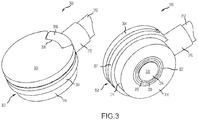
- a BTC probe 300 may comprise a housing 302 and a cap 304 enclosing an interior volume of the housing 302 when coupled at a top surface of a body 407 of the housing 302.
- housing 302 may comprise a portion of rub strip 214, or may comprise a portion of a turbine case, or a compressor case.
- cap 304 may comprise an alignment feature 306 configured to align with an alignment block 308 of housing 302.
- housing 302 may further comprise a body 307 having a top surface and a cylindrical portion 314 extending toward a bottom surface 316.
- a neck 310 may extend radially from body 307 and alignment block 308 may comprise a portion of neck 310.
- a hard lead 312 may be inserted through housing 302 via neck 310.
- Housing 302 may enclose a sensor element 324.
- a sensor head 326 of sensor element 324 may extend through bottom surface 316.
- Sensor element 324 may be surrounded by an inner hat insulator 318, an inner housing 320 and an outer hat insulator 322.
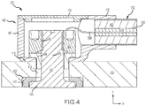
- a BTC probe 300 may comprise a housing 402 having features, geometries, construction, materials, manufacturing techniques, and/or internal components similar to housing 302.
- Housing 402 may be mounted radially outward of a structure 404 such as, for example, a turbine case or a compressor case.
- Housing 402 may comprise a body 407 having neck 410 extending radially from the body 407 configured to accept hard lead 312.
- Housing 402 may further comprise a cap 405 enclosing an interior volume of the housing 402 when coupled at a top surface of body 407.
- Body 407 may comprise a bottom surface 416 opposite the top surface and in contact with structure 404.
- Bottom surface 416 may be positioned proximate bore 418 and counterbore 420 through structure 404.
- Sensor element 424 may be inserted into bore 418 and counterbore 420 with shank 428 of sensor element 424 extending radially through structure 404 into housing 402.
- Shank 428 may be coupled at threaded coupling 430 to nut 432 and insulated from contact with body 407 and structure 404 by hat insulator 434. With nut 432 coupled to shank 428 sensor head 426 of sensor element 424 may be drawn to rest within counterbore 429 against counterbore insulator 422. In this regard, sensor element 424 may couple housing 402 to structure 404.
- a hard lead such as hard lead 312 may be a driven guard hard lead and comprise a lead wire 508 surrounded by a driven guard 506 containing a first layer of insulating material 504 therein.
- Driven guard 506 is surrounded by a second layer of insulating material 504 contained within a hard shield 502 such as, for example, a metallic tube such as one of a steel, a stainless steel, an alloy, and/or an aluminum.
- a length L1 of driven guard 406 and a length L2 of lead wire 408 are exposed for assembly.
- Lead wire 408 is coupled to and is in electronic communication with a sensor element, such as sensor element 324 or 424.
- hard shield 502 is coupled to and in electronic communication with a housing such as housing 302 or 402.
- driven guard 506 may be coupled to and in electronic communication with an interior structure of a housing such as, for example, inner housing 320.
- a hard lead such as hard lead 312 may have a diameter about 0.125 in. (3.175 mm) where about in this context means +/-0.015 in. (0.381 mm).
- Triangular head 600a is defined at first vertex 602a, second vertex 604a, and third vertex 606a each having a corresponding interior angle.
- Triangular head 600a may be defined by first vertex 602a, second vertex 604a, and third vertex 606a to have a desired planform such as, for example, isosceles, equilateral, scalene, acute, obtuse, right, and/or the like.
- Quadrilateral head 600b is defined at first vertex 602b, second vertex 604b, third vertex 606b, and fourth vertex 608b each having a corresponding interior angle.
- quadrilateral head may define a quadrilateral having a desired planform such as, for example, rectangular, square, rhomboidal, trapezoidal, frustoconical, and/or the like.
- a cranked arrow head 600g is defined at first vertex 602g, second vertex 604g, third vertex 606g, and fourth vertex 608g with a fifth vertex 610g and a sixth vertex 612g.
- the fifth vertex 610g and the sixth vertex 612g may define an area of relatively increased or decreased X-Z slope along the perimeter of the cranked arrow head 600g between each of their respective adjacent vertexes.
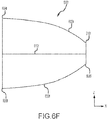
- a concave head 600c may comprise a concave curve 602c and may be defined between a first vertex 604c a second vertex 606c and a third vertex 608c.
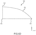
- a convex head 600d may comprise a convex curve 602d and may be defined between a first vertex 604d a second vertex 606d and a third vertex 608d.
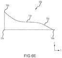
- a compound curved head 600e may comprise a compound curve 602e and may be defined between a first vertex 604e a second vertex 606e and a third vertex 608e.
- Compound curve 602e may comprise a local plateau 610e defined by a region of relatively low X-Z slope along the perimeter of the compound curved head where the ratio of change in Z-axis position with respect to X-axis position is less than or equal 1:10.
- the local plateau 610e may have a region where the slope is zero.
- curved heads may be unilateral or bilateral.
- the curve of a curved head may be mirrored about a centerline (i.e., 612f) perpendicular to a line defined between the first vertex (e.g., 604c, 604e, 604f) and the second vertex (e.g., 606c, 606e, 606f).
- any of the curves (602c, 602d, 602e) may be offset relative to the Z-axis and/or truncated with respect to the X-axis tending thereby to define a frustum or half-frustum with the third vertex (e.g., 608f) and a fourth vertex (e.g., 610f).
- any of the vertexes of the various heads (600a, 600b, 600c, 600d, 600e, 600f, and 600g) may be rounded tending thereby to ease manufacturing and reduce stress concentrations which may develop at hard corners.
- a sensor element of BTC probe 300 such as sensor element 324 or sensor element 424, may be energized by lead wire 508 and an electric field flows between the sensor element a ground plane such as, for example, structure.
- a blade tip such as tip 205 of blade 206, passes proximate to sensor element 324, an electric field tends to flow across gap 215 into the blade tip inducing a capacitance between the blade tip and the sensor element 324 which tends to vary with respect to the width of gap 215.
- the gap between a non-continuous target (e.g., a blade tip of a turbine blade) and a sensor head may be determined as a function of the change in capacitance occurring at a frequency which is a function of the time the blade tip dwells within the electric field.
- a BTC probe 300 may be used to measure a gap between a probe head and other rotating components of gas turbine engine 20 which may be continuous or nearly continuous targets such as, for example, a knife edge seal.
- System 700 may comprise sensors 702, controller 704, and a display system 706.
- Sensors 702 may be in electronic communication with controller 704 and comprise one or more BTC probes 300.
- Sensors 702 may output sensor data 708 to controller 704.
- sensor data 708 may comprise a time varying signal with respect to a voltage (i.e., a time variant voltage signal).
- the peak voltage of the time variant voltage signal may be a function of the distance between the target (e.g., a blade tip) and the sensor.
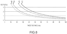
- the voltage signal function for a target distance may vary dependent upon target axial position as shown in FIG. 8.
- FIG. 8 illustrates four voltage-distance curves X1, X2, X3, and X4 each correlated to an axial position (for example a position along axis A-A' of gas turbine engine 20) of a target such as, for example, a blade tip or knife edge seal.
- the a sensor head of the BTC probe 300 may be configured as described with reference to FIGs. 6A-6G above to generate a desired position (axial or radial) variant response (i.e., variant with respect to the position of a target) in the time varying signal of sensor data 708.
- sensors 702 may comprise a first BTC sensor configured to generate an axial position variant response in the time varying signal.
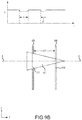
- a pulse width of the time variant voltage signal may vary with respect to axial position as shown in FIG. 9A .
- FIG. 9A illustrates the path of blade tips 900 over a triangular head 904 of a first BTC sensor and a rectangular quadrilateral head 906 of a second BTC sensor.
- Blade tips 900 may shift axially (X-axis) with respect to triangular head 904 as indicated by arrow 902 along the axis of rotation A-A' of a gas turbine engine.
- the pulse width P of a first time variant voltage signal 904' from the first BTC sensor may change from a first pulse width P1 to a second pulse width P2.
- controller 704 may determine an axial position of a rotating target such as blade tips 900 based on the variance between the first pulse width P1 and the second pulse width P2.
- P1 may be correlated with a first voltage-distance curve (e.g., X1) and P2 may be correlated with a second voltage-distance curve (e.g., X2).
- a radial distance between the first BTC sensor and the target such as blade tips 900 may be determined based on a voltage distance curve calibrated to the axial position of the target.
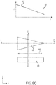
- controller 704 may determine an axial position of a rotating target such as knife edge seal 908.
- Knife edge seal may shift axially along axis of rotation A-A' of a gas turbine with respect to triangular head 904 to a position 908'.
- Knife edge seal 908 may comprise a small gap 910.
- the pulse width from the first BTC sensor may change from a first pulse width P to a second pulse width P' as marked between dropouts produced by gap 910 from a relatively steady state voltage.
- the steady state voltage may between about 1 volt to about 100 millivolts where about in this context means ⁇ 50 millivolts..
- controller 704 may determine an axial position of a rotating target such as knife edge seal 912 which may be a continuous target. As knife edge seal 912 shifts axially as indicated by arrow 902, voltage variance with respect to time may be relatively steady state. However, in response to an axial shift in the knife edge seal 912 the first BTC sensor may generate a position variant voltage signal 904" while the second BTC sensor may generate a relatively steady state voltage signal 906". In this regard, controller 704 may determine the axial shift of the knife edge seal 912 as a function of the position variant voltage signal and the stead state voltage signal. In various embodiments, controller 704 may determine a target background error correction based on the steady state voltage signal.
- display system 706 may be in electronic communication with controller 704 and receive position data 710 from controller 704.
- Display system 706 may comprise hardware and/or software configured to display position data 710.
- the position data 710 may comprise engineering units describing an axial shift (along the X-axis, i.e. the axis of rotation of gas turbine engine 20) of a rotating component with respect to the position of a sensor.
- the position data 710 may comprise engineering units describing a radial gap between the rotating component and the sensor.
- System 400 may be computer based, and may comprise a processor, a tangible non-transitory computer-readable memory, and/or a network interface, along with other suitable system software and hardware components.
- controller 704 may be implemented in a single processor or one or more processors configured to implement various logical operations in response to execution of instructions, for example, instructions stored on a non-transitory, tangible, computer-readable medium such as, for example, memory 712 which may store data used, for example, for trending and analysis/prognosis purposes.
- the one or more processors can be a general purpose processor, a microprocessor, a microcontroller, a digital signal processor (DSP), an application specific integrated circuit (ASIC), a field programmable gate array (FPGA) or other programmable logic device, discrete gate or transistor logic, discrete hardware components, or any combination thereof.
- controller 704 may be configured as a central network element or hub to access various systems, engines, and components of system 700.
- controller 704 may comprise a network, computer-based system, and/or software components configured to provide an access point to various systems, engines, and components of system 700.
- a method 1000 of determining the position of a rotating component may comprise controller 704 receiving sensor data 708 comprising a first time variant voltage signal (step 1002) from BTC probe 300. Controller 704 may extract a first pulse width and a second pulse width from the sensor data 708 (step 1004). Controller 704 may determine an axial position of a rotating target (such as, for example, blade tips 900, knife edge seal 908, or knife edge seal 912) based on the variance between the first pulse width and the second pulse width (step 1006). Controller 704 may select a voltage-distance curve based on the first pulse width and the second pulse width (step 1008).
- a rotating target such as, for example, blade tips 900, knife edge seal 908, or knife edge seal 912
- Controller 704 may determine a radial position of the rotating target based on the voltage component of the first time voltage signal and the voltage distance curve (step 1010). In various embodiments, controller 704 may receive a second a second time variant voltage signal. In various embodiments, controller 704 may determine the axial position of the rotating target based a voltage variance between the first time variant voltage signal and the second time variant voltage signal, wherein the voltage variance with respect to time is relatively steady state for each of the first time variant voltage signal and the second time variant voltage signal.
- references to “one embodiment”, “an embodiment”, “an example embodiment”, etc. indicate that the embodiment described may include a particular feature, structure, or characteristic, but every embodiment may not necessarily include the particular feature, structure, or characteristic. Moreover, such phrases are not necessarily referring to the same embodiment. Further, when a particular feature, structure, or characteristic is described in connection with an embodiment, it is submitted that it is within the knowledge of one skilled in the art to affect such feature, structure, or characteristic in connection with other embodiments whether or not explicitly described. After reading the description, it will be apparent to one skilled in the relevant art(s) how to implement the disclosure in alternative embodiment
Landscapes
- Engineering & Computer Science (AREA)
- Physics & Mathematics (AREA)
- General Physics & Mathematics (AREA)
- Mechanical Engineering (AREA)
- General Engineering & Computer Science (AREA)
- Structures Of Non-Positive Displacement Pumps (AREA)
- Transmission And Conversion Of Sensor Element Output (AREA)
- Measurement Of Length, Angles, Or The Like Using Electric Or Magnetic Means (AREA)
Priority Applications (1)
| Application Number | Priority Date | Filing Date | Title |
|---|---|---|---|
| EP22165257.1A EP4040101B1 (fr) | 2018-06-19 | 2019-06-19 | Systèmes et procédés pour des ensembles sonde de capacité pseudo-triaxiale |
Applications Claiming Priority (1)
| Application Number | Priority Date | Filing Date | Title |
|---|---|---|---|
| US16/012,632 US10641596B2 (en) | 2018-06-19 | 2018-06-19 | Systems and methods for pseudo-triaxial capacitance probe assemblies |
Related Child Applications (2)
| Application Number | Title | Priority Date | Filing Date |
|---|---|---|---|
| EP22165257.1A Division EP4040101B1 (fr) | 2018-06-19 | 2019-06-19 | Systèmes et procédés pour des ensembles sonde de capacité pseudo-triaxiale |
| EP22165257.1A Division-Into EP4040101B1 (fr) | 2018-06-19 | 2019-06-19 | Systèmes et procédés pour des ensembles sonde de capacité pseudo-triaxiale |
Publications (3)
| Publication Number | Publication Date |
|---|---|
| EP3584531A2 true EP3584531A2 (fr) | 2019-12-25 |
| EP3584531A3 EP3584531A3 (fr) | 2020-03-04 |
| EP3584531B1 EP3584531B1 (fr) | 2022-05-04 |
Family
ID=66999572
Family Applications (2)
| Application Number | Title | Priority Date | Filing Date |
|---|---|---|---|
| EP19181174.4A Active EP3584531B1 (fr) | 2018-06-19 | 2019-06-19 | Systèmes et procédés pour des ensembles de sonde de capacité pseudo-triaxiale |
| EP22165257.1A Active EP4040101B1 (fr) | 2018-06-19 | 2019-06-19 | Systèmes et procédés pour des ensembles sonde de capacité pseudo-triaxiale |
Family Applications After (1)
| Application Number | Title | Priority Date | Filing Date |
|---|---|---|---|
| EP22165257.1A Active EP4040101B1 (fr) | 2018-06-19 | 2019-06-19 | Systèmes et procédés pour des ensembles sonde de capacité pseudo-triaxiale |
Country Status (2)
| Country | Link |
|---|---|
| US (1) | US10641596B2 (fr) |
| EP (2) | EP3584531B1 (fr) |
Cited By (1)
| Publication number | Priority date | Publication date | Assignee | Title |
|---|---|---|---|---|
| EP4524372A1 (fr) * | 2023-09-15 | 2025-03-19 | RTX Corporation | Stator à hauteur radiale réglable |
Families Citing this family (4)
| Publication number | Priority date | Publication date | Assignee | Title |
|---|---|---|---|---|
| US12553796B2 (en) | 2023-03-14 | 2026-02-17 | Rtx Corporation | Measurement system having a probe for measuring parameters of a turbine engine |
| US12421866B2 (en) * | 2023-09-15 | 2025-09-23 | Rtx Corporation | Anti-rotation feature for instrumentation of gas turbine engine |
| CN120008453B (zh) * | 2023-11-16 | 2025-11-25 | 中国航发商用航空发动机有限责任公司 | 篦齿叶尖间隙和轴向间隙测量装置、系统和航空发动机 |
| FR3160435A1 (fr) * | 2024-03-20 | 2025-09-26 | Safran Aircraft Engines | Turbomachine d’aeronef |
Family Cites Families (13)
| Publication number | Priority date | Publication date | Assignee | Title |
|---|---|---|---|---|
| DE3617373A1 (de) | 1986-05-23 | 1987-11-26 | Mtu Muenchen Gmbh | Kapazitives messsystem |
| US5119036A (en) | 1990-05-29 | 1992-06-02 | General Electric Company | Electrical capacitance clearanceometer |
| US5101165A (en) | 1990-05-29 | 1992-03-31 | General Electric Company | Electrical capacitance clearanceometer |
| GB0713108D0 (en) * | 2007-07-06 | 2007-08-15 | Rolls Royce Plc | Displacement measurement arrangement |
| DE102007051027A1 (de) | 2007-10-25 | 2009-04-30 | Mtu Aero Engines Gmbh | Strömungsmaschine, Spaltmesssystem und Verfahren zum Ermitteln eines Rotorspaltes |
| US8970228B2 (en) | 2012-05-31 | 2015-03-03 | General Electric Company | Rotational clearance measurement system and method of operation |
| US9316479B2 (en) | 2012-09-20 | 2016-04-19 | United Technologies Corporation | Capacitance based clearance probe and housing |
| ES2574436T3 (es) * | 2013-05-22 | 2016-06-17 | Mtu Aero Engines Gmbh | Grado de turbomáquina y método para determinar una ranura de obturación y/o una posición axial de semejante grado de turbomáquina |
| US9341462B2 (en) | 2013-10-09 | 2016-05-17 | Siemens Energy, Inc | Sensor for measuring blade tip clearance in gas turbines |
| GB2522210B (en) | 2014-01-16 | 2018-10-10 | Weston Aerospace Ltd | Engine probe |
| WO2016077328A1 (fr) * | 2014-11-10 | 2016-05-19 | In-Situ, Inc. | Capteur compact pour mesurer la turbidité ou la fluorescence dans un échantillon de fluide |
| CN105588509A (zh) | 2015-12-16 | 2016-05-18 | 中国航空工业集团公司沈阳发动机设计研究所 | 一种叶尖间隙动态测量系统 |
| US10557373B2 (en) * | 2017-12-05 | 2020-02-11 | United Technologies Corporation | Low profile embedded blade tip clearance probe assembly |
-
2018
- 2018-06-19 US US16/012,632 patent/US10641596B2/en active Active
-
2019
- 2019-06-19 EP EP19181174.4A patent/EP3584531B1/fr active Active
- 2019-06-19 EP EP22165257.1A patent/EP4040101B1/fr active Active
Cited By (1)
| Publication number | Priority date | Publication date | Assignee | Title |
|---|---|---|---|---|
| EP4524372A1 (fr) * | 2023-09-15 | 2025-03-19 | RTX Corporation | Stator à hauteur radiale réglable |
Also Published As
| Publication number | Publication date |
|---|---|
| EP4040101B1 (fr) | 2024-11-27 |
| EP3584531A3 (fr) | 2020-03-04 |
| US20190383594A1 (en) | 2019-12-19 |
| EP4040101A1 (fr) | 2022-08-10 |
| EP3584531B1 (fr) | 2022-05-04 |
| US10641596B2 (en) | 2020-05-05 |
Similar Documents
| Publication | Publication Date | Title |
|---|---|---|
| EP3584531B1 (fr) | Systèmes et procédés pour des ensembles de sonde de capacité pseudo-triaxiale | |
| EP3845747B1 (fr) | Systèmes et procédés d'alimentation auxiliaire de pile à combustible dans des applications de carburant secondaires | |
| EP3361229B1 (fr) | Système et procédé de surveillance de la santé de la pale de rotor | |
| JP5825811B2 (ja) | タービンエンジンにおける先端クリアランスの算出に関する方法、システム及び装置 | |
| US20140007591A1 (en) | Advanced tip-timing measurement blade mode identification | |
| EP3462033B1 (fr) | Procédé permettant d'assurer la surveillance de l'érosion et/ou de la corrosion dans une machine et machine | |
| US2575710A (en) | Apparatus for measuring rotor blade vibration | |
| EP3620797B1 (fr) | Système et support de stockage lisible par ordinateur pour des sondes aérodynamiques à alignement variable | |
| US11686577B2 (en) | Anti-rotation method for angled face cap probe | |
| US20190072511A1 (en) | Near full hoop electrical axial shift wear indication sensor | |
| EP3477047B1 (fr) | Liaisons structurelles segmentées pour accord de fréquence de disque et moteur à turbine à gaz associé ayant telles liaisons | |
| JP6371039B2 (ja) | 対流増加器を有するプロセスセンサ | |
| JP2010237208A (ja) | 過渡クリアランス測定のための時間表示摩擦ピン及び関連する方法 | |
| EP3628962A1 (fr) | Système et procédé de mesure d'interstices entre des composants rotatifs et fixes d'une turbomachine | |
| EP3502425A1 (fr) | Indicateur d'usure à base de capacité et procédé de mesure d'éloignement | |
| RU2593427C2 (ru) | Устройство и способ измерения времени прохождения вершин лопаток в турбомашине | |
| US10371497B2 (en) | Fully integral epoxy cap probe | |
| EP3748134B1 (fr) | Formes de profil aérodynamique à aube pour éléments intégrés | |
| EP2012086A1 (fr) | Capteur de déplacement | |
| US10641595B2 (en) | Low profile triaxial blade tip clearance probe assembly with driven guard | |
| EP4303406A1 (fr) | Système et procédé de détermination de déplacement orbital du rotor | |
| US20200072076A1 (en) | Embedded triaxial epoxy cap probe | |
| US12298197B2 (en) | System and method for reducing motoring time in a turbomachine based on shaft deflection | |
| EP4497913A1 (fr) | Test de résonance compensé par un processus de surface portante de moteur in situ | |
| Cherrett et al. | Unsteady three-dimensional flow in a single-stage transonic fan: Part I—Unsteady rotor exit flow field |
Legal Events
| Date | Code | Title | Description |
|---|---|---|---|
| PUAI | Public reference made under article 153(3) epc to a published international application that has entered the european phase |
Free format text: ORIGINAL CODE: 0009012 |
|
| STAA | Information on the status of an ep patent application or granted ep patent |
Free format text: STATUS: THE APPLICATION HAS BEEN PUBLISHED |
|
| AK | Designated contracting states |
Kind code of ref document: A2 Designated state(s): AL AT BE BG CH CY CZ DE DK EE ES FI FR GB GR HR HU IE IS IT LI LT LU LV MC MK MT NL NO PL PT RO RS SE SI SK SM TR |
|
| AX | Request for extension of the european patent |
Extension state: BA ME |
|
| PUAL | Search report despatched |
Free format text: ORIGINAL CODE: 0009013 |
|
| AK | Designated contracting states |
Kind code of ref document: A3 Designated state(s): AL AT BE BG CH CY CZ DE DK EE ES FI FR GB GR HR HU IE IS IT LI LT LU LV MC MK MT NL NO PL PT RO RS SE SI SK SM TR |
|
| AX | Request for extension of the european patent |
Extension state: BA ME |
|
| RIC1 | Information provided on ipc code assigned before grant |
Ipc: G01B 7/14 20060101AFI20200124BHEP Ipc: F01D 21/00 20060101ALN20200124BHEP |
|
| STAA | Information on the status of an ep patent application or granted ep patent |
Free format text: STATUS: REQUEST FOR EXAMINATION WAS MADE |
|
| 17P | Request for examination filed |
Effective date: 20200903 |
|
| RBV | Designated contracting states (corrected) |
Designated state(s): AL AT BE BG CH CY CZ DE DK EE ES FI FR GB GR HR HU IE IS IT LI LT LU LV MC MK MT NL NO PL PT RO RS SE SI SK SM TR |
|
| RAP1 | Party data changed (applicant data changed or rights of an application transferred) |
Owner name: RAYTHEON TECHNOLOGIES CORPORATION |
|
| GRAP | Despatch of communication of intention to grant a patent |
Free format text: ORIGINAL CODE: EPIDOSNIGR1 |
|
| STAA | Information on the status of an ep patent application or granted ep patent |
Free format text: STATUS: GRANT OF PATENT IS INTENDED |
|
| RIC1 | Information provided on ipc code assigned before grant |
Ipc: F01D 21/00 20060101ALN20211109BHEP Ipc: F01D 17/02 20060101ALI20211109BHEP Ipc: F01D 11/14 20060101ALI20211109BHEP Ipc: G01B 7/14 20060101AFI20211109BHEP |
|
| INTG | Intention to grant announced |
Effective date: 20211203 |
|
| GRAS | Grant fee paid |
Free format text: ORIGINAL CODE: EPIDOSNIGR3 |
|
| GRAA | (expected) grant |
Free format text: ORIGINAL CODE: 0009210 |
|
| STAA | Information on the status of an ep patent application or granted ep patent |
Free format text: STATUS: THE PATENT HAS BEEN GRANTED |
|
| AK | Designated contracting states |
Kind code of ref document: B1 Designated state(s): AL AT BE BG CH CY CZ DE DK EE ES FI FR GB GR HR HU IE IS IT LI LT LU LV MC MK MT NL NO PL PT RO RS SE SI SK SM TR |
|
| REG | Reference to a national code |
Ref country code: GB Ref legal event code: FG4D |
|
| REG | Reference to a national code |
Ref country code: CH Ref legal event code: EP |
|
| REG | Reference to a national code |
Ref country code: AT Ref legal event code: REF Ref document number: 1489484 Country of ref document: AT Kind code of ref document: T Effective date: 20220515 |
|
| REG | Reference to a national code |
Ref country code: DE Ref legal event code: R096 Ref document number: 602019014355 Country of ref document: DE |
|
| REG | Reference to a national code |
Ref country code: IE Ref legal event code: FG4D |
|
| REG | Reference to a national code |
Ref country code: LT Ref legal event code: MG9D |
|
| REG | Reference to a national code |
Ref country code: NL Ref legal event code: MP Effective date: 20220504 |
|
| REG | Reference to a national code |
Ref country code: AT Ref legal event code: MK05 Ref document number: 1489484 Country of ref document: AT Kind code of ref document: T Effective date: 20220504 |
|
| PG25 | Lapsed in a contracting state [announced via postgrant information from national office to epo] |
Ref country code: SE Free format text: LAPSE BECAUSE OF FAILURE TO SUBMIT A TRANSLATION OF THE DESCRIPTION OR TO PAY THE FEE WITHIN THE PRESCRIBED TIME-LIMIT Effective date: 20220504 Ref country code: PT Free format text: LAPSE BECAUSE OF FAILURE TO SUBMIT A TRANSLATION OF THE DESCRIPTION OR TO PAY THE FEE WITHIN THE PRESCRIBED TIME-LIMIT Effective date: 20220905 Ref country code: NO Free format text: LAPSE BECAUSE OF FAILURE TO SUBMIT A TRANSLATION OF THE DESCRIPTION OR TO PAY THE FEE WITHIN THE PRESCRIBED TIME-LIMIT Effective date: 20220804 Ref country code: NL Free format text: LAPSE BECAUSE OF FAILURE TO SUBMIT A TRANSLATION OF THE DESCRIPTION OR TO PAY THE FEE WITHIN THE PRESCRIBED TIME-LIMIT Effective date: 20220504 Ref country code: LT Free format text: LAPSE BECAUSE OF FAILURE TO SUBMIT A TRANSLATION OF THE DESCRIPTION OR TO PAY THE FEE WITHIN THE PRESCRIBED TIME-LIMIT Effective date: 20220504 Ref country code: HR Free format text: LAPSE BECAUSE OF FAILURE TO SUBMIT A TRANSLATION OF THE DESCRIPTION OR TO PAY THE FEE WITHIN THE PRESCRIBED TIME-LIMIT Effective date: 20220504 Ref country code: GR Free format text: LAPSE BECAUSE OF FAILURE TO SUBMIT A TRANSLATION OF THE DESCRIPTION OR TO PAY THE FEE WITHIN THE PRESCRIBED TIME-LIMIT Effective date: 20220805 Ref country code: FI Free format text: LAPSE BECAUSE OF FAILURE TO SUBMIT A TRANSLATION OF THE DESCRIPTION OR TO PAY THE FEE WITHIN THE PRESCRIBED TIME-LIMIT Effective date: 20220504 Ref country code: ES Free format text: LAPSE BECAUSE OF FAILURE TO SUBMIT A TRANSLATION OF THE DESCRIPTION OR TO PAY THE FEE WITHIN THE PRESCRIBED TIME-LIMIT Effective date: 20220504 Ref country code: BG Free format text: LAPSE BECAUSE OF FAILURE TO SUBMIT A TRANSLATION OF THE DESCRIPTION OR TO PAY THE FEE WITHIN THE PRESCRIBED TIME-LIMIT Effective date: 20220804 Ref country code: AT Free format text: LAPSE BECAUSE OF FAILURE TO SUBMIT A TRANSLATION OF THE DESCRIPTION OR TO PAY THE FEE WITHIN THE PRESCRIBED TIME-LIMIT Effective date: 20220504 |
|
| PG25 | Lapsed in a contracting state [announced via postgrant information from national office to epo] |
Ref country code: RS Free format text: LAPSE BECAUSE OF FAILURE TO SUBMIT A TRANSLATION OF THE DESCRIPTION OR TO PAY THE FEE WITHIN THE PRESCRIBED TIME-LIMIT Effective date: 20220504 Ref country code: PL Free format text: LAPSE BECAUSE OF FAILURE TO SUBMIT A TRANSLATION OF THE DESCRIPTION OR TO PAY THE FEE WITHIN THE PRESCRIBED TIME-LIMIT Effective date: 20220504 Ref country code: LV Free format text: LAPSE BECAUSE OF FAILURE TO SUBMIT A TRANSLATION OF THE DESCRIPTION OR TO PAY THE FEE WITHIN THE PRESCRIBED TIME-LIMIT Effective date: 20220504 Ref country code: IS Free format text: LAPSE BECAUSE OF FAILURE TO SUBMIT A TRANSLATION OF THE DESCRIPTION OR TO PAY THE FEE WITHIN THE PRESCRIBED TIME-LIMIT Effective date: 20220904 |
|
| PG25 | Lapsed in a contracting state [announced via postgrant information from national office to epo] |
Ref country code: SM Free format text: LAPSE BECAUSE OF FAILURE TO SUBMIT A TRANSLATION OF THE DESCRIPTION OR TO PAY THE FEE WITHIN THE PRESCRIBED TIME-LIMIT Effective date: 20220504 Ref country code: SK Free format text: LAPSE BECAUSE OF FAILURE TO SUBMIT A TRANSLATION OF THE DESCRIPTION OR TO PAY THE FEE WITHIN THE PRESCRIBED TIME-LIMIT Effective date: 20220504 Ref country code: RO Free format text: LAPSE BECAUSE OF FAILURE TO SUBMIT A TRANSLATION OF THE DESCRIPTION OR TO PAY THE FEE WITHIN THE PRESCRIBED TIME-LIMIT Effective date: 20220504 Ref country code: EE Free format text: LAPSE BECAUSE OF FAILURE TO SUBMIT A TRANSLATION OF THE DESCRIPTION OR TO PAY THE FEE WITHIN THE PRESCRIBED TIME-LIMIT Effective date: 20220504 Ref country code: DK Free format text: LAPSE BECAUSE OF FAILURE TO SUBMIT A TRANSLATION OF THE DESCRIPTION OR TO PAY THE FEE WITHIN THE PRESCRIBED TIME-LIMIT Effective date: 20220504 Ref country code: CZ Free format text: LAPSE BECAUSE OF FAILURE TO SUBMIT A TRANSLATION OF THE DESCRIPTION OR TO PAY THE FEE WITHIN THE PRESCRIBED TIME-LIMIT Effective date: 20220504 |
|
| REG | Reference to a national code |
Ref country code: CH Ref legal event code: PL |
|
| REG | Reference to a national code |
Ref country code: DE Ref legal event code: R097 Ref document number: 602019014355 Country of ref document: DE |
|
| REG | Reference to a national code |
Ref country code: BE Ref legal event code: MM Effective date: 20220630 |
|
| PG25 | Lapsed in a contracting state [announced via postgrant information from national office to epo] |
Ref country code: MC Free format text: LAPSE BECAUSE OF FAILURE TO SUBMIT A TRANSLATION OF THE DESCRIPTION OR TO PAY THE FEE WITHIN THE PRESCRIBED TIME-LIMIT Effective date: 20220504 |
|
| PLBE | No opposition filed within time limit |
Free format text: ORIGINAL CODE: 0009261 |
|
| STAA | Information on the status of an ep patent application or granted ep patent |
Free format text: STATUS: NO OPPOSITION FILED WITHIN TIME LIMIT |
|
| PG25 | Lapsed in a contracting state [announced via postgrant information from national office to epo] |
Ref country code: AL Free format text: LAPSE BECAUSE OF FAILURE TO SUBMIT A TRANSLATION OF THE DESCRIPTION OR TO PAY THE FEE WITHIN THE PRESCRIBED TIME-LIMIT Effective date: 20220504 |
|
| 26N | No opposition filed |
Effective date: 20230207 |
|
| PG25 | Lapsed in a contracting state [announced via postgrant information from national office to epo] |
Ref country code: LU Free format text: LAPSE BECAUSE OF NON-PAYMENT OF DUE FEES Effective date: 20220619 Ref country code: LI Free format text: LAPSE BECAUSE OF NON-PAYMENT OF DUE FEES Effective date: 20220630 Ref country code: IE Free format text: LAPSE BECAUSE OF NON-PAYMENT OF DUE FEES Effective date: 20220619 Ref country code: CH Free format text: LAPSE BECAUSE OF NON-PAYMENT OF DUE FEES Effective date: 20220630 |
|
| PG25 | Lapsed in a contracting state [announced via postgrant information from national office to epo] |
Ref country code: SI Free format text: LAPSE BECAUSE OF FAILURE TO SUBMIT A TRANSLATION OF THE DESCRIPTION OR TO PAY THE FEE WITHIN THE PRESCRIBED TIME-LIMIT Effective date: 20220504 Ref country code: BE Free format text: LAPSE BECAUSE OF NON-PAYMENT OF DUE FEES Effective date: 20220630 |
|
| P01 | Opt-out of the competence of the unified patent court (upc) registered |
Effective date: 20230521 |
|
| PG25 | Lapsed in a contracting state [announced via postgrant information from national office to epo] |
Ref country code: IT Free format text: LAPSE BECAUSE OF FAILURE TO SUBMIT A TRANSLATION OF THE DESCRIPTION OR TO PAY THE FEE WITHIN THE PRESCRIBED TIME-LIMIT Effective date: 20220504 |
|
| PG25 | Lapsed in a contracting state [announced via postgrant information from national office to epo] |
Ref country code: MK Free format text: LAPSE BECAUSE OF FAILURE TO SUBMIT A TRANSLATION OF THE DESCRIPTION OR TO PAY THE FEE WITHIN THE PRESCRIBED TIME-LIMIT Effective date: 20220504 Ref country code: CY Free format text: LAPSE BECAUSE OF FAILURE TO SUBMIT A TRANSLATION OF THE DESCRIPTION OR TO PAY THE FEE WITHIN THE PRESCRIBED TIME-LIMIT Effective date: 20220504 |
|
| PG25 | Lapsed in a contracting state [announced via postgrant information from national office to epo] |
Ref country code: HU Free format text: LAPSE BECAUSE OF FAILURE TO SUBMIT A TRANSLATION OF THE DESCRIPTION OR TO PAY THE FEE WITHIN THE PRESCRIBED TIME-LIMIT; INVALID AB INITIO Effective date: 20190619 |
|
| PG25 | Lapsed in a contracting state [announced via postgrant information from national office to epo] |
Ref country code: TR Free format text: LAPSE BECAUSE OF FAILURE TO SUBMIT A TRANSLATION OF THE DESCRIPTION OR TO PAY THE FEE WITHIN THE PRESCRIBED TIME-LIMIT Effective date: 20220504 |
|
| PG25 | Lapsed in a contracting state [announced via postgrant information from national office to epo] |
Ref country code: MT Free format text: LAPSE BECAUSE OF FAILURE TO SUBMIT A TRANSLATION OF THE DESCRIPTION OR TO PAY THE FEE WITHIN THE PRESCRIBED TIME-LIMIT Effective date: 20220504 |
|
| PG25 | Lapsed in a contracting state [announced via postgrant information from national office to epo] |
Ref country code: BG Free format text: LAPSE BECAUSE OF FAILURE TO SUBMIT A TRANSLATION OF THE DESCRIPTION OR TO PAY THE FEE WITHIN THE PRESCRIBED TIME-LIMIT Effective date: 20220504 |
|
| PG25 | Lapsed in a contracting state [announced via postgrant information from national office to epo] |
Ref country code: BG Free format text: LAPSE BECAUSE OF FAILURE TO SUBMIT A TRANSLATION OF THE DESCRIPTION OR TO PAY THE FEE WITHIN THE PRESCRIBED TIME-LIMIT Effective date: 20220504 |
|
| PGFP | Annual fee paid to national office [announced via postgrant information from national office to epo] |
Ref country code: DE Payment date: 20250520 Year of fee payment: 7 |
|
| PGFP | Annual fee paid to national office [announced via postgrant information from national office to epo] |
Ref country code: GB Payment date: 20250520 Year of fee payment: 7 |
|
| PGFP | Annual fee paid to national office [announced via postgrant information from national office to epo] |
Ref country code: FR Payment date: 20250520 Year of fee payment: 7 |
|
| REG | Reference to a national code |
Ref country code: DE Ref legal event code: R081 Ref document number: 602019014355 Country of ref document: DE Owner name: RTX CORPORATION (N.D.GES.D. STAATES DELAWARE),, US Free format text: FORMER OWNER: RAYTHEON TECHNOLOGIES CORPORATION, FARMINGTON, CT, US |