EP4524626A1 - Fibre à cristal photonique à maintien de polarisation - Google Patents
Fibre à cristal photonique à maintien de polarisation Download PDFInfo
- Publication number
- EP4524626A1 EP4524626A1 EP23197186.2A EP23197186A EP4524626A1 EP 4524626 A1 EP4524626 A1 EP 4524626A1 EP 23197186 A EP23197186 A EP 23197186A EP 4524626 A1 EP4524626 A1 EP 4524626A1
- Authority
- EP
- European Patent Office
- Prior art keywords
- region
- pcf
- stress
- stress applying
- inner cladding
- Prior art date
- Legal status (The legal status is an assumption and is not a legal conclusion. Google has not performed a legal analysis and makes no representation as to the accuracy of the status listed.)
- Withdrawn
Links
- 239000000835 fiber Substances 0.000 title claims abstract description 48
- 239000004038 photonic crystal Substances 0.000 title claims abstract description 12
- 230000010287 polarization Effects 0.000 title claims abstract description 12
- 238000005253 cladding Methods 0.000 claims abstract description 202
- 239000000463 material Substances 0.000 claims abstract description 59
- 238000004519 manufacturing process Methods 0.000 claims description 9
- 230000001902 propagating effect Effects 0.000 claims description 7
- VYPSYNLAJGMNEJ-UHFFFAOYSA-N Silicium dioxide Chemical compound O=[Si]=O VYPSYNLAJGMNEJ-UHFFFAOYSA-N 0.000 description 44
- 239000000377 silicon dioxide Substances 0.000 description 22
- 230000003287 optical effect Effects 0.000 description 14
- 230000008901 benefit Effects 0.000 description 4
- 230000000694 effects Effects 0.000 description 4
- 239000013307 optical fiber Substances 0.000 description 4
- 238000009826 distribution Methods 0.000 description 3
- 239000003292 glue Substances 0.000 description 3
- 238000000034 method Methods 0.000 description 2
- 230000001681 protective effect Effects 0.000 description 2
- KRHYYFGTRYWZRS-UHFFFAOYSA-M Fluoride anion Chemical compound [F-] KRHYYFGTRYWZRS-UHFFFAOYSA-M 0.000 description 1
- 229910019142 PO4 Inorganic materials 0.000 description 1
- 238000004026 adhesive bonding Methods 0.000 description 1
- 230000005540 biological transmission Effects 0.000 description 1
- 150000004770 chalcogenides Chemical class 0.000 description 1
- 230000007423 decrease Effects 0.000 description 1
- -1 fluorozirconate) Chemical compound 0.000 description 1
- 239000011521 glass Substances 0.000 description 1
- 230000006698 induction Effects 0.000 description 1
- 238000005259 measurement Methods 0.000 description 1
- 230000000116 mitigating effect Effects 0.000 description 1
- NBIIXXVUZAFLBC-UHFFFAOYSA-K phosphate Chemical compound [O-]P([O-])([O-])=O NBIIXXVUZAFLBC-UHFFFAOYSA-K 0.000 description 1
- 239000010452 phosphate Substances 0.000 description 1
- 229920000642 polymer Polymers 0.000 description 1
- 239000002861 polymer material Substances 0.000 description 1
- 239000007787 solid Substances 0.000 description 1
- 230000003595 spectral effect Effects 0.000 description 1
- SITVSCPRJNYAGV-UHFFFAOYSA-L tellurite Chemical compound [O-][Te]([O-])=O SITVSCPRJNYAGV-UHFFFAOYSA-L 0.000 description 1
Images



Classifications
-
- G—PHYSICS
- G02—OPTICS
- G02B—OPTICAL ELEMENTS, SYSTEMS OR APPARATUS
- G02B6/00—Light guides; Structural details of arrangements comprising light guides and other optical elements, e.g. couplings
- G02B6/02—Optical fibres with cladding with or without a coating
- G02B6/024—Optical fibres with cladding with or without a coating with polarisation maintaining properties
-
- C—CHEMISTRY; METALLURGY
- C03—GLASS; MINERAL OR SLAG WOOL
- C03B—MANUFACTURE, SHAPING, OR SUPPLEMENTARY PROCESSES
- C03B37/00—Manufacture or treatment of flakes, fibres, or filaments from softened glass, minerals, or slags
- C03B37/01—Manufacture of glass fibres or filaments
- C03B37/012—Manufacture of preforms for drawing fibres or filaments
- C03B37/01205—Manufacture of preforms for drawing fibres or filaments starting from tubes, rods, fibres or filaments
- C03B37/01211—Manufacture of preforms for drawing fibres or filaments starting from tubes, rods, fibres or filaments by inserting one or more rods or tubes into a tube
- C03B37/01217—Manufacture of preforms for drawing fibres or filaments starting from tubes, rods, fibres or filaments by inserting one or more rods or tubes into a tube for making preforms of polarisation-maintaining optical fibres
-
- C—CHEMISTRY; METALLURGY
- C03—GLASS; MINERAL OR SLAG WOOL
- C03B—MANUFACTURE, SHAPING, OR SUPPLEMENTARY PROCESSES
- C03B37/00—Manufacture or treatment of flakes, fibres, or filaments from softened glass, minerals, or slags
- C03B37/01—Manufacture of glass fibres or filaments
- C03B37/012—Manufacture of preforms for drawing fibres or filaments
- C03B37/01205—Manufacture of preforms for drawing fibres or filaments starting from tubes, rods, fibres or filaments
- C03B37/01211—Manufacture of preforms for drawing fibres or filaments starting from tubes, rods, fibres or filaments by inserting one or more rods or tubes into a tube
- C03B37/0122—Manufacture of preforms for drawing fibres or filaments starting from tubes, rods, fibres or filaments by inserting one or more rods or tubes into a tube for making preforms of photonic crystal, microstructured or holey optical fibres
-
- G—PHYSICS
- G02—OPTICS
- G02B—OPTICAL ELEMENTS, SYSTEMS OR APPARATUS
- G02B6/00—Light guides; Structural details of arrangements comprising light guides and other optical elements, e.g. couplings
- G02B6/02—Optical fibres with cladding with or without a coating
- G02B6/02295—Microstructured optical fibre
- G02B6/02314—Plurality of longitudinal structures extending along optical fibre axis, e.g. holes
- G02B6/02342—Plurality of longitudinal structures extending along optical fibre axis, e.g. holes characterised by cladding features, i.e. light confining region
- G02B6/02357—Property of longitudinal structures or background material varies radially and/or azimuthally in the cladding, e.g. size, spacing, periodicity, shape, refractive index, graded index, quasiperiodic, quasicrystals
-
- C—CHEMISTRY; METALLURGY
- C03—GLASS; MINERAL OR SLAG WOOL
- C03B—MANUFACTURE, SHAPING, OR SUPPLEMENTARY PROCESSES
- C03B2201/00—Type of glass produced
- C03B2201/06—Doped silica-based glasses
- C03B2201/08—Doped silica-based glasses doped with boron or fluorine or other refractive index decreasing dopant
- C03B2201/10—Doped silica-based glasses doped with boron or fluorine or other refractive index decreasing dopant doped with boron
-
- C—CHEMISTRY; METALLURGY
- C03—GLASS; MINERAL OR SLAG WOOL
- C03B—MANUFACTURE, SHAPING, OR SUPPLEMENTARY PROCESSES
- C03B2203/00—Fibre product details, e.g. structure, shape
- C03B2203/30—Polarisation maintaining [PM], i.e. birefringent products, e.g. with elliptical core, by use of stress rods, "PANDA" type fibres
- C03B2203/31—Polarisation maintaining [PM], i.e. birefringent products, e.g. with elliptical core, by use of stress rods, "PANDA" type fibres by use of stress-imparting rods, e.g. by insertion
-
- C—CHEMISTRY; METALLURGY
- C03—GLASS; MINERAL OR SLAG WOOL
- C03B—MANUFACTURE, SHAPING, OR SUPPLEMENTARY PROCESSES
- C03B2203/00—Fibre product details, e.g. structure, shape
- C03B2203/42—Photonic crystal fibres, e.g. fibres using the photonic bandgap PBG effect, microstructured or holey optical fibres
Definitions
- the invention relates to a polarization maintaining, PM, photonic crystal fibre, PCF.
- the invention further relates to a preform for fabricating the PM PCF and to a fibre assembly comprising the PM PCF.
- LMA Large mode area, LMA, polarization maintaining, PM, photonic crystal fibres, PCF, (also known as 'micro-structured fibres') can be designed to be endlessly single-mode (i.e. to have no higher order mode cut-off), deliver excellent mode quality at all wavelengths, and exhibit low loss while keeping an almost constant mode field diameter. This makes them ideal for multi-wavelength transmission and delivery of short optical pulses, and to be used as single-mode PM fibre pigtails.
- LMA PM PCFs require, or benefit from, the LMA PM PCF being connectorized, i.e. having an optical fibre connector provided at one end.
- the LMA PM PCF can thus be turned into an optical fibre cable or patch cord that can be easily connected to an optical input and/or output of an optical device.
- WO 2005/059612 describes a LMA PM PCF comprising stress rods provided within the PCF microstructure cladding region, which cause stress induced birefringence in the PCF core region.
- An aspect provides a polarization maintaining, PM, photonic crystal fibre, PCF, comprising a core region for propagating light in a longitudinal direction of the PM PCF, an inner cladding region and an outer cladding region.
- the inner cladding region surrounds the core region.
- the inner cladding region comprises a plurality of microstructure elements extending in said longitudinal direction in a cladding background material having a first coefficient of thermal expansion.
- the microstructure elements are arranged in a first lattice having a first pitch between centres of neighbouring elements.
- the outer cladding region surrounds the inner cladding region.
- the outer cladding region comprises said cladding background material having said first coefficient of thermal expansion, a first stress applying region and a second stress applying region.
- the first stress applying region and the second stress applying region are each formed of a plurality of stress elements of a material having a second coefficient of thermal expansion different to the first coefficient of thermal expansion.
- the stress elements of each said stress applying region extend in said longitudinal direction and are arranged in a respective second lattice.
- the locations of the first stress applying region and the second stress applying region relative to the core region and the microstructure elements, the first coefficient of thermal expansion, and the second coefficient of thermal expansion are configured to cause a stress induced birefringence in the core region of the PM PCF.
- the structure of the PM PCF may enable improved cross-sectional roundness of the PM PCF outer diameter, which may enable improved connectorization of the fibre, in particular when the PM PCF is fixated inside a fibre ferrule e.g., by gluing the fibre to the inner surface of the ferrule.
- the structure of the stress applying regions may enable improved positioning of the stress applying regions within the PM PCF, which may advantageously provide improved cross-sectional roundness of the PM PCF.
- the presence of stress applying regions in the outer cladding region of a PM PCF may result in various distortions of the PM PCF outer surface causing the circumference to deviate from a perfect circle.
- the fibre diameter in the axis of the stress applying regions can differ from the fibre diameter along an axis perpendicular thereto. This can make the cross-sectional shape of the outer surface of the fibre slightly elliptical.
- the introduction of the stress applying regions causes a kink to form on the outer surface of the PM PCF.
- Such distortions of the outer surface of the fibre can cause problems when the fibre is glued inside a fibre ferrule, where a difference in glue thickness due to the distortion of the fibre circumference may introduce a stress field with counteracts the stress in the fibre core induced by the stress applying regions.
- the distortion of the outer fibre diameter is compensated by increasing the thickness of the outermost fibre region surrounding the outer cladding region to smoothen out the distortion.
- the non-circularity describes the deviation of the PM PCF's cross-sectional shape from a perfect circle and is determined by dividing a difference between a maximum value, A, and a minimum value, B, of relative values for the fibre outer diameter, D, by a mean value of the relative values, i.e. 2 ⁇ (A-B)/(A+B).
- the non-circularity 2 ⁇ (A-B)/(A+B) is below 0.02, such as below 0.01, such as below 0.0075, such as below 0.005.
- the structure of the stress applying regions may enable improved positioning of the stress applying regions relative to the inner cladding region and/or the core region, which may advantageously provide improved stress induced birefringence in the core region of the PM PCF.
- An improved positioning of the stress applying regions may also provide that distortion of the fibre diameter by the stress applying regions is reduced thereby mitigating the associated problems without the need for adding a thick region of fibre material, e.g., a thick ring of cladding background material, surrounding the outer cladding. This provides that a strong stress-induced birefringence can be obtained in a substantially circular fibre without the need for increasing the fibre diameter significantly. For example, in some cases providing that the PM PCF has an outer diameter of 125 ⁇ m ensures compatibility with standard fibre optical components while still obtaining a strong birefringence.
- the core region is preferably solid.
- the core region comprises a silica material.
- the structure of the stress applying regions may enable tilt of the stress applying regions relative to the inner cladding region to be reduced or avoided.
- Tilt is the angle between any symmetry axis of the inner cladding region and the nearest symmetry axis of the stress applying region.
- the structure of the stress applying regions may enable improved shape of the stress applying regions, which may advantageously provide improved cross-sectional roundness of the PM PCF.
- the improved shape of the stress applying regions may also provide improved stress induced birefringence in the core region of the PM PCF.
- the first stress applying region and the second stress applying region are located in the cladding background material outside the inner cladding region.
- the first stress applying region and the second stress applying region are located adjacent the inner cladding region, i.e., adjacent to the arrangement of microstructural elements. This may advantageously cause maximum stress to be applied to the core region, resulting in maximum induced birefringence in the core region for a given diameter of the inner cladding region.
- the first lattice and the second lattice have the same lattice structure. This may advantageously enable improved shape and/or positioning of the stress applying regions within the outer cladding region, which may advantageously maximise the induced birefringence in the core region and provide improved cross-sectional roundness of the PM PCF.
- the first lattice and the second lattice are hexagonal lattices, i.e., where the microstructural elements and the plurality of stress elements arranged in hexagonal lattices.
- each said stress applying region are arranged in a respective second lattice with said first pitch between centres of neighbouring stress elements. Using the same pitch may provide the advantage of easier stacking of the preform from which the PM PCF is produced.
- each said stress applying region are arranged in a respective second lattice with a pitch between centres of neighbouring stress elements that is different to the first pitch.
- the microstructure elements in the inner cladding region forms a hexagonal arrangement such that the inner cladding region has a substantially hexagonal cross-sectional shape with a 6-fold symmetry.
- the sides of the inner cladding region facing the stress applying regions are straight or convex.
- a first side of the first stress applying region is located adjacent a first side of the inner cladding region and a first side of the second stress applying region is located adjacent a second side of the inner cladding region, opposite the first side of the inner cladding region.
- the first stress applying region and the second stress applying region respectively define a first recess and a second recess in cross-section.
- the first stress applying region is located adjacent the inner cladding region with a first corner of the inner cladding region nested in the first recess.
- the second stress applying region is located adjacent the inner cladding region with a second corner of the inner cladding region, opposite the first corner, nested in the second recess.
- the first pitch is less than 9 ⁇ m. This may advantageously enable the PM PCF to have a core diameter of up to 10 ⁇ m and a standard outer diameter of 125 ⁇ m or 230 ⁇ m, while having strong birefringence in the core and improved cross-sectional roundness of the outer diameter.
- the first pitch is in the range 3 ⁇ m to 7 ⁇ m. This may advantageously enable the PM PCF to have a core diameter of up to 10 ⁇ m and a standard outer diameter of 125 ⁇ m or 230 ⁇ m, while having strong birefringence in the core and improved cross-sectional roundness of the outer diameter of the PM PCF.
- the PM PCF has an outer diameter and the first pitch is less than 3% of the outer diameter. This may advantageously enable the PM PCF to have a core diameter of up to 10 ⁇ m and a standard outer diameter of 125 ⁇ m or 230 ⁇ m, while having strong birefringence in the core and improved cross-sectional roundness of the outer diameter of the PM PCF.
- the outer diameter is 125 ⁇ m and the first pitch is less than 4 ⁇ m to within manufacturing tolerances.
- the outer diameter is 125 ⁇ m and the first pitch is 3.3 ⁇ m to within manufacturing tolerances. This may advantageously enable the PM PCF to have a core diameter in the region of 5 ⁇ m and a standard outer diameter, while having strong birefringence in the core and improved cross-sectional roundness of the outer diameter of the PM PCF.
- the outer diameter is 230 ⁇ m and the first pitch is less than 7 ⁇ m to within manufacturing tolerances.
- the outer diameter is 230 ⁇ m and the first pitch is 6.5 ⁇ m to within manufacturing tolerances. This may advantageously enable the PM PCF to have a core diameter in the region of 10 ⁇ m and a standard outer diameter, while having strong birefringence in the core and improved cross-sectional roundness of the outer diameter of the PM PCF.
- the cladding background material is Silica and the stress elements are formed of Boron-doped Silica, thereby taking advantage of industry standard, proven technology for manufacturing optical waveguides.
- Other materials may be used though, e.g. fluoride (e.g. fluorozirconate), tellurite, phosphate or chalcogenide based glasses or polymer materials, whereby the fibre may be optimised for particularly strong birefringence and/or specific wavelengths/wavelength ranges.
- the ratio between the shortest distance from the stress applying regions to the outer surface of the fibre and the diameter of the inner cladding region is between 0.5 and 1.5, such as between 0,75 and 1,25, such as between 0.9 and 1.1. This may advantageously enable the PM PCF to have a relatively large inner cladding region to provide strong confinement of light to the core region while ensuring an improved roundness even for a relatively small outer diameter of the PM PCF.
- the hexagonal arrangement in the inner cladding region comprises 4 layers of microstructure elements surrounding the core region, such as 5 layers of microstructure elements surrounding the core region.
- the light guiding properties of the PM PCF generally improves with increasing number of layers of microstructure elements, while the stress induced birefringence decreases with increasing distance between the core region and the stress applying regions. For some values of the first pitch a strong guidance and a strong birefringence is obtained with 4 layers of microstructure elements.
- the layers of microstructure elements may be substantially complete to improve the guiding properties of the core region.
- 4 or 5 layers of microstructure elements is arranged between the core region and the outer cladding region along an axis extending between the stress applying regions.
- the preform comprises stacked longitudinal preform elements comprising a preform core rod, a plurality of preform inner cladding capillary tubes of the cladding background material, a plurality of preform stress element rods of said material having said second coefficient of thermal expansion, a plurality of preform outer cladding rods of the cladding background material, and a preform stacking tube.
- the preform inner cladding capillary tubes are stacked in an inner cladding region around the preform core rod in a said first lattice having a second pitch between centres of neighbouring capillary tubes; the second pitch is greater than the first pitch.
- the preform stress element rods are stacked in a respective said second lattice having said second pitch between centres of neighbouring stress element rods.
- the preform outer cladding rods are stacked in an outer cladding region around the inner cladding region, the first stress region and the second stress region.
- the preform core rod, the preform inner cladding capillary tubes, the preform stress element rods and the preform outer cladding rods are located within the preform stacking tube.
- the preform stress element rods are arranged outside the inner cladding region in a first stress applying region and in a second stress applying region.
- An aspect provides a fibre assembly comprising an optical connector and a PM PCF.
- the optical connector comprises a connector housing and a connector sub-assembly including a ferrule. An end of the PM PCF is located and glued within the ferrule.
- the PM PCF comprises a core region for propagating light in a longitudinal direction of the PM PCF, an inner cladding region and an outer cladding region.
- the inner cladding region surrounds the core region.
- the inner cladding region comprises a plurality of microstructure elements extending in said longitudinal direction in a cladding background material having a first coefficient of thermal expansion.
- the microstructure elements are arranged in a first lattice having a first pitch between centres of neighbouring elements.
- the outer cladding region surrounds the inner cladding region.
- the outer cladding region comprises said cladding background material having said first coefficient of thermal expansion, a first stress applying region and a second stress applying region.
- the first stress applying region and the second stress applying region are each formed of a plurality of stress elements of a material having a second coefficient of thermal expansion different to the first coefficient of thermal expansion.
- the stress elements of each said stress applying region extend in said longitudinal direction and are arranged in a respective second lattice with said first pitch between centres of neighbouring stress elements.
- the locations of the first stress applying region and the second stress applying region relative to the core region and the microstructure elements, the first coefficient of thermal expansion, and the second coefficient of thermal expansion are configured to cause a stress induced birefringence in the core region of the PM PCF.
- the structure of the PM PCF may enable improved cross-sectional roundness of the PM PCF outer diameter, which may enable improved connectorization of the fibre.
- the structure of the stress applying regions may enable improved positioning of the stress applying regions within the PM PCF, which may advantageously provide improved cross-sectional roundness of the PM PCF.
- the structure of the stress applying regions may enable improved shape of the stress applying regions, which may advantageously provide improved cross-sectional roundness of the PM PCF.
- Improved cross-sectional roundness of the PM PCF outer diameter may advantageously improve the distribution of the glue around the PM PCF outer diameter within the ferrule. This may advantageously mitigate reduction of the stress experienced within the core region of the PM PCF caused by uneven distribution of glue around the PM PCF outer diameter, and thus mitigate corresponding reduction in the stress induced birefringence in the core region of the PM PCF.
- Optical fibres according to the present invention have a longitudinal direction and a cross section perpendicular thereto.
- the cross section of a photonic crystal fibre may vary along its length, but is typically constant.
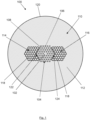
- an embodiment provides a polarization maintaining, PM, photonic crystal fibre, PCF, 100 comprising a core region 102 for propagating light in a longitudinal direction of the PM PCF, an inner cladding region 104 surrounding the core region, and an outer cladding region 110 surrounding the inner cladding region.
- the inner cladding region comprises a plurality of microstructure elements in the form of microstructural holes 106 provided in cladding background material 108.
- the microstructural holes extend in the longitudinal direction of the PM PCF and are arranged (as viewed in the cross-section of the PM PCF 100, as illustrated in Figure 1 ) in a first lattice.
- the first lattice is a substantially hexagonal lattice (i.e. the lengths of the edges of the unit cell of the lattice structure, and the angles between them, result in unit cells that are substantially hexagonal in shape) and has a first pitch between centres of neighbouring elements (i.e. between neighbouring unit cells).
- the cladding background material has a first coefficient of thermal expansion, and may, for example, be Silica.
- the core region may also be Silica.
- the outer cladding region comprises cladding background material 112, a first stress applying region 114 and a second stress applying region 116.
- the cladding background material has the first coefficient of thermal expansion, i.e. it is the same material as the cladding background material of the inner cladding region.
- the cladding background material 112 may, for example, be Silica.
- the first stress applying region and the second stress applying region are located in the cladding background material, outside the inner cladding region.
- the first stress applying region and the second stress applying region are located adjacent the inner cladding region.
- the stress applying regions do not overlap the inner cladding region.
- the inner cladding region 104 has a substantially hexagonal cross-sectional shape.
- the first stress applying region 114 defines a first recess 122 and the second stress applying region 116 defines a second recess 124, as viewed in cross-section (as illustrated in Figure 1 ).
- the first stress applying region is located adjacent the inner cladding region with a first corner of the inner cladding region nested in the first recess.
- the second stress applying region is located adjacent the inner cladding region with a second corner of the inner cladding region, opposite the first corner, nested in the second recess.
- the first stress applying region and the second stress applying region are each formed of a plurality of stress elements 118.
- the stress elements are formed of a material having a second coefficient of thermal expansion different to the first coefficient of thermal expansion.
- the stress elements may, for example, be formed of Boron-doped Silica.
- the stress elements 118 of each stress applying region extend in the longitudinal direction of the PM PCF 100. Within each stress applying region, the stress elements are arranged in a respective second lattice.
- the second lattice is a substantially hexagonal lattice (i.e. the lattice structure is formed of lattice cells that are substantially hexagonal in shape) and has the same pitch as the first lattice, i.e. the second lattice has the same pitch between centres of neighbouring stress elements as is between the centres of neighbouring elements of the inner cladding region.
- the locations of the first stress applying region and the second stress applying region relative to the core region and the microstructure elements, the first coefficient of thermal expansion, and the second coefficient of thermal expansion are configured to cause a stress induced birefringence in the core region 102 of the PM PCF 100.
- Anisotropic deformation of the core region due to the stress applying regions or a resulting anisotropic strain field (or stress field) induced in the core region by the stress applying regions results - due to the elasto-optic effect - in the material of the core region becoming birefringent, whereby different polarization states experience different refractive indices, providing a means for separating the two polarization states of a given longitudinal mode, and optionally eliminating one of them.
- An 'anisotropic strain field' will be understood to mean a strain field that is different in size in two different directions of a cross section of the core region.
- micro-structured fibre enabling single-mode operation over a large wavelength range
- induction of an anisotropic strain field in the core region providing birefringence
- the ⁇ core region' is defined - when viewed in a cross section perpendicular to a longitudinal direction of the fibre - as a (typically central) light-propagating part of the fibre.
- the core region is limited in a radial direction by the microstructure elements of the inner cladding region.
- ⁇ coefficient of thermal expansion is generally meant the volume coefficient of thermal expansion.
- the difference between the first coefficient of thermal expansion and the second coefficient of thermal expansion is sufficiently large to generate a total strain in the core region to result in a birefringence of at least 0.5 ⁇ 10 -5 , such as larger than 5 ⁇ 10 -5 , such as larger than 10 -4 .
- the degree of birefringence of an optical waveguide is defined by the difference between the effective mode indices in the two primary polarisation states.
- Configuring the first coefficient of thermal expansion and the second coefficient of thermal expansion to cause a stress induced birefringence in the core region of the PM PCF can include configuring the relative magnitude of the coefficients of thermal expansion, depending on the materials used and their temperature dependencies.
- the relative difference between the first coefficient of thermal expansion and the second coefficient of thermal expansion numerically is larger than 1%, such as larger than 5%, such as larger than 10%.
- the numerical value of the difference between the first coefficient of thermal expansion and the second coefficient of thermal expansion is larger than 0.1*10 -6 K -1 , such as larger than 0.5*10 -6 K -1 , such as larger than 1.0*10 -6 K -1 .
- the first pitch is less than 9 ⁇ m.
- the first pitch is in the range 3 ⁇ m to 7Dm.
- the PM PCF 100 has an outer diameter and the first pitch is less than 3% of the outer diameter.
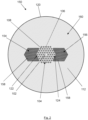
- an embodiment provides a polarization maintaining, PM, photonic crystal fibre, PCF, 150 comprising a core region 102 for propagating light in a longitudinal direction of the PM PCF, an inner cladding region 104 surrounding the core region, and an outer cladding region 160 surrounding the inner cladding region.
- the core region 102 and the inner cladding region 104 are as described above.
- the outer cladding region comprises cladding background material 112, a first stress applying region 154 and a second stress applying region 156.
- the cladding background material has the first coefficient of thermal expansion, i.e. it is the same material as the cladding background material of the inner cladding region.
- the cladding background material 112 may, for example, be Silica.
- the first stress applying region and the second stress applying region are located in the cladding background material, outside the inner cladding region.
- the first stress applying region and the second stress applying region are located adjacent the inner cladding region.
- the stress applying regions do not overlap the inner cladding region.
- the inner cladding region 104 has a substantially hexagonal cross-sectional shape.
- the first stress applying region 154 defines a first recess 122 and the second stress applying region 156 defines a second recess 124, as viewed in cross-section (as illustrated in Figure 1 ).
- the first stress applying region is located adjacent the inner cladding region with a first corner of the inner cladding region nested in the first recess.
- the second stress applying region is located adjacent the inner cladding region with a second corner of the inner cladding region, opposite the first corner, nested in the second recess.
- the first stress applying region and the second stress applying region are each formed of a plurality of stress elements 158.
- the stress elements are formed of a material having a second coefficient of thermal expansion different to the first coefficient of thermal expansion.
- the stress elements may, for example, be formed of Boron-doped Silica.
- the stress elements 158 of each stress applying region extend in the longitudinal direction of the PM PCF 100.
- the stress elements are arranged in a respective second lattice.
- the second lattice is a substantially hexagonal lattice (i.e. the lattice structure is formed of lattice cells that are substantially hexagonal in shape).
- the second lattice has a different pitch to the first lattice.
- the pitch of the second lattice is one half of the first pitch i.e. the pitch between centres of neighbouring stress elements is one half of the pitch between the centres of neighbouring elements of the inner cladding region.
- the locations of the first stress applying region and the second stress applying region relative to the core region and the microstructure elements, the first coefficient of thermal expansion, and the second coefficient of thermal expansion are configured to cause a stress induced birefringence in the core region 102 of the PM PCF 150.
- the first pitch is less than 9 ⁇ m.
- the first pitch is in the range 3 ⁇ m to 7 ⁇ m.
- the PM PCF 100 has an outer diameter and the first pitch is less than 3% of the outer diameter.
- an embodiment provides a PM PCF 200 comprising a core region 102 for propagating light in a longitudinal direction of the PM PCF, an inner cladding region 104 surrounding the core region, and an outer cladding region 110 surrounding the inner cladding region, having the same structure as PM PCF 100 described above.
- the outer diameter 220 of the PM PCF 200 is close to circular in cross-section.
- the PM PCF 200 of this embodiment has an outer diameter of 125 ⁇ m and the pitch between the microstructure elements and between the stress elements 118 (i.e. the first pitch) is 3.3 ⁇ m (to within manufacturing tolerances).
- the core region 102 is a 5 ⁇ m core.
- the PM PCF 200 may have an outer diameter of 230 ⁇ m, a first pitch of 6.5 ⁇ m (to within manufacturing tolerances) and a 10 ⁇ m core.
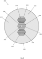
- an embodiment provides a PM PCF 300 comprising a core region 202 for propagating light in a longitudinal direction of the PM PCF, an inner cladding region 204 surrounding the core region, and an outer cladding region 210 surrounding the inner cladding region.
- the inner cladding region comprises a plurality of microstructure elements in the form of microstructural holes 206 provided in cladding background material 208.
- the microstructure elements extend in the longitudinal direction of the PM PCF and are arranged (as viewed in the cross-section of the PM PCF 300, as illustrated in Figure 3 ) in a first lattice.
- the first lattice is a substantially hexagonal lattice and has a first pitch between centres of neighbouring elements.
- the cladding background material has a first coefficient of thermal expansion, and may, for example, be Silica.
- the core region may also be Silica.
- the outer cladding region comprises cladding background material 212, a first stress applying region 214 and a second stress applying region 216.
- the cladding background material has the first coefficient of thermal expansion, i.e. it is the same material as the cladding background material of the inner cladding region.
- the cladding background material 212 may, for example, be Silica.
- the first stress applying region and the second stress applying region are located in the cladding background material, outside the inner cladding region.
- the first stress applying region and the second stress applying region are located adjacent the inner cladding region.
- the stress applying regions do not overlap the inner cladding region.
- the inner cladding region 204 has a substantially hexagonal cross-sectional shape.
- a first side of the first stress applying region 214 is located adjacent a first side of the inner cladding region 204.
- a first side of the second stress applying region 216 is located adjacent a second side of the inner cladding region, opposite the first side of the inner cladding region.
- the first stress applying region and the second stress applying region are each formed of a plurality of stress elements 218.
- the stress elements are formed of a material having a second coefficient of thermal expansion different to the first coefficient of thermal expansion.
- the stress elements may, for example, be formed of Boron-doped Silica.
- the stress elements 218 of each stress applying region extend in the longitudinal direction of the PM PCF 300. Within each stress applying region, the stress elements are arranged in a respective second lattice.
- the second lattice is a substantially hexagonal lattice and has the same pitch as the first lattice.
- the locations of the first stress applying region and the second stress applying region relative to the core region and the microstructure elements, the first coefficient of thermal expansion, and the second coefficient of thermal expansion are configured to cause a stress induced birefringence in the core region 202 of the PM PCF 300.
- an embodiment provides a preform 400 for fabricating a PM PCF 100, 200 as described above with reference to Figure 1 or Figure 3 .
- the preform 400 comprises stacked longitudinal preform elements comprising a preform core rod 402, a plurality of preform inner cladding capillary tubes 404, a plurality of preform stress element rods 406, a plurality of preform outer cladding rods 408 and a preform stacking tube 410.
- the preform inner cladding capillary tubes 404 are made of cladding background material and are stacked in an inner cladding region 412 around the preform core rod 402.
- the cladding background material has a first coefficient of thermal expansion, and may, for example, be Silica.
- the preform core rod 402 may also be made of Silica.
- the preform inner cladding capillary tubes are stacked in a first lattice.
- the first lattice is a substantially hexagonal lattice and has a second pitch between centres of neighbouring capillary tubes.
- the preform stress element rods 406 are made of a material having a second coefficient of thermal expansion, different to the first coefficient of thermal expansion.
- the preform stress element rods may, for example, be formed of Boron-doped Silica.
- the preform stress element rods are arranged outside the inner cladding region 412 in a first stress applying region 414 and in a second stress applying region 416. Within each stress applying region 414, 416 the preform stress element rods are stacked in a second lattice having the second pitch between centres of neighbouring stress element rods, i.e. the second lattice has the same pitch between centres of neighbouring stress elements as is between neighbouring preform inner cladding capillary tubes 404.
- the inner cladding region 412 has a substantially hexagonal cross-sectional shape.
- the first stress applying region 414 defines a first recess 422 and the second stress applying region defines a second recess 424, as viewed in cross-section (as illustrated in Figure 4 ).
- the first stress applying region is located adjacent the inner cladding region with a first corner of the inner cladding region nested in the first recess.
- the second stress applying region is located adjacent the inner cladding region with a second corner of the inner cladding region, opposite the first corner, nested in the second recess.
- each stress applying region 414, 416 and the inner cladding region 412 there may be a gap between each stress applying region 414, 416 and the inner cladding region 412, formed by providing a row of preform outer cladding rods 408 between each stress applying region 414, 416 and the inner cladding region 412.
- the preform outer cladding rods 408 are formed of the cladding background material.
- the preform outer cladding rods are stacked in an outer cladding region 420, around the inner cladding region 412, the first stress region 414 and the second stress region 416.
- the preform inner cladding capillary tubes 404, the preform stress element rods 406 and the preform outer cladding rods 408 are located within the preform stacking tube 410.
- a PM PCF 100, 200 may be fabricated by drawing a fibre from the preform 400, using the method described by Bjarklev, Broeng and Bjarklev in "Photonic Crystal Fibres", Kluwer Academic Press, 2003 chapter 4, pp. 115-130 .
- the PM PCF drawn from the preform 400 will have corresponding structural elements of corresponding relative size(s) and form(s) as the preform.
- the second pitch of the first and second lattices of the preform will be reduced to a smaller pitch, i.e. the first pitch of the first and second lattice of the PM PCF 100, 200, during fibre draw.
- the preform stress element rods 406 made of Boron-doped Silica will contract by a different amount to the preform core rod 402, the preform inner cladding capillary tubes 404, and the preform outer cladding rods 408 made of Silica when the fibre is cooled below the softening temperature/s of these materials.
- a stress distribution will be present in the resulting PM PCF, and due to the elasto-optic effect the silica material will become birefringent.
- the stress field in the core region 10 determines the modal birefringence of the guided modes. Since the elasto-optic effect is substantially constant as a function of wavelength, the PM PCFs 100, 200 enable single-mode guidance with constant birefringence in a very broad spectral range.
- an embodiment provides a preform 500 for fabricating a PM PCF 300 as described above with reference to Figure 4 .
- the preform 500 comprises stacked longitudinal preform elements comprising a preform core rod 502, a plurality of preform inner cladding capillary tubes 504, a plurality of preform stress element rods 506, a plurality of preform outer cladding rods 508 and a preform stacking tube 510.
- the preform inner cladding capillary tubes 504 are made of cladding background material and are stacked in an inner cladding region 512 around the preform core rod 502.
- the cladding background material has a first coefficient of thermal expansion, and may, for example, be Silica.
- the preform core rod 502 may also be made of Silica.
- the preform inner cladding capillary tubes are stacked in a first lattice.
- the first lattice is a substantially hexagonal lattice and has a second pitch between centres of neighbouring capillary tubes.
- the preform stress element rods 506 are made of a material having a second coefficient of thermal expansion, different to the first coefficient of thermal expansion.
- the preform stress element rods may, for example, be formed of Boron-doped Silica.
- the preform stress element rods are arranged outside the inner cladding region 512 in a first stress applying region 514 and in a second stress applying region 516. Within each stress applying region 514, 516 the preform stress element rods are stacked in a second lattice having the second pitch between centres of neighbouring stress element rods, i.e. the second lattice has the same pitch between centres of neighbouring stress elements as is between neighbouring preform inner cladding capillary tubes 504.
- the inner cladding region 512 has a substantially hexagonal cross-sectional shape.
- a first side of the first stress applying region 514 is located adjacent a first side of the inner cladding region 512.
- a first side of the second stress applying region 516 is located adjacent a second side of the inner cladding region, opposite the first side of the inner cladding region.
- the preform outer cladding rods 508 are formed of the cladding background material.
- the preform outer cladding rods are stacked in an outer cladding region 520, around the inner cladding region 512, the first stress region 514 and the second stress region 516.
- the preform inner cladding capillary tubes 504, the preform stress element rods 506 and the preform outer cladding rods 508 are located within the preform stacking tube 510.
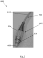
- FIG. 7 shows a part of a fibre assembly 600 according to an embodiment.
- the fibre assembly comprises an optical connector 602 and a PM PCF 100, as described above.
- the optical connector comprises a connector housing 604 and a connector sub-assembly 606 including a ferrule 608. It will be understood that any of the PM PCFs 100, 200, 300 described above may be used.
- An end of the PM PCF 100 is cleaved to form an end facet, the microstructure elements within an end section of the PM PCF may then be collapsed and the end facet polished.
- This end of the PM PCF is located and glued within the ferrule 608.
- the end facet of the PM PCF is located in an output plane of the optical connector by aligning the end facet of the PM PCF with an output end of the ferrule.
- the PM PCF is aligned inside the ferrule so that the core region of the PM PCF is centred inside a connector plane of the optical connector.
- the PM PCF may also be orientated so that its polarization axis lies in a predetermined plane.
- the PM PCF 100 may be provided with a protective jacket 610, such as a polymer protective jacket.
- the optical connector 602 may, for example, be an optical fibre connector of the type which in the prior art is commonly used to terminate the end of a standard optical fibre to enable easy connection and disconnection to a light source or to a sensor etc.
- optical fibre connectors Many different types have been introduced to the market, such as e.g. FC, E-2000, SMA connectors, as well as connectors with built in beam expansion.
Landscapes
- Chemical & Material Sciences (AREA)
- Physics & Mathematics (AREA)
- Engineering & Computer Science (AREA)
- Optics & Photonics (AREA)
- General Life Sciences & Earth Sciences (AREA)
- Life Sciences & Earth Sciences (AREA)
- Geochemistry & Mineralogy (AREA)
- Manufacturing & Machinery (AREA)
- Materials Engineering (AREA)
- Organic Chemistry (AREA)
- General Physics & Mathematics (AREA)
- Crystallography & Structural Chemistry (AREA)
- Optical Fibers, Optical Fiber Cores, And Optical Fiber Bundles (AREA)
Priority Applications (2)
| Application Number | Priority Date | Filing Date | Title |
|---|---|---|---|
| EP23197186.2A EP4524626A1 (fr) | 2023-09-13 | 2023-09-13 | Fibre à cristal photonique à maintien de polarisation |
| PCT/EP2024/075291 WO2025056567A1 (fr) | 2023-09-13 | 2024-09-11 | Fibre à cristal photonique à maintien de polarisation |
Applications Claiming Priority (1)
| Application Number | Priority Date | Filing Date | Title |
|---|---|---|---|
| EP23197186.2A EP4524626A1 (fr) | 2023-09-13 | 2023-09-13 | Fibre à cristal photonique à maintien de polarisation |
Publications (1)
| Publication Number | Publication Date |
|---|---|
| EP4524626A1 true EP4524626A1 (fr) | 2025-03-19 |
Family
ID=88021124
Family Applications (1)
| Application Number | Title | Priority Date | Filing Date |
|---|---|---|---|
| EP23197186.2A Withdrawn EP4524626A1 (fr) | 2023-09-13 | 2023-09-13 | Fibre à cristal photonique à maintien de polarisation |
Country Status (2)
| Country | Link |
|---|---|
| EP (1) | EP4524626A1 (fr) |
| WO (1) | WO2025056567A1 (fr) |
Citations (5)
| Publication number | Priority date | Publication date | Assignee | Title |
|---|---|---|---|---|
| WO2005059612A1 (fr) | 2003-12-19 | 2005-06-30 | Crystal Fibre A/S | Fibres cristallines photoniques contenant des elements de contrainte |
| EP2228673A1 (fr) * | 2008-11-05 | 2010-09-15 | Fujikura, Ltd. | Fibre à bande interdite photonique |
| US20160245989A1 (en) * | 2013-11-22 | 2016-08-25 | Imra America, Inc. | Polarizing and polarization maintaining leakage channel fibers |
| CN113126200A (zh) * | 2021-03-17 | 2021-07-16 | 中国科学院西安光学精密机械研究所 | 应力诱导的高双折射超大模场光子晶体光纤 |
| CN114200573A (zh) * | 2021-11-19 | 2022-03-18 | 淮阴工学院 | 基于液体填充的高非线性高双折射光子晶体保偏光纤 |
-
2023
- 2023-09-13 EP EP23197186.2A patent/EP4524626A1/fr not_active Withdrawn
-
2024
- 2024-09-11 WO PCT/EP2024/075291 patent/WO2025056567A1/fr active Pending
Patent Citations (5)
| Publication number | Priority date | Publication date | Assignee | Title |
|---|---|---|---|---|
| WO2005059612A1 (fr) | 2003-12-19 | 2005-06-30 | Crystal Fibre A/S | Fibres cristallines photoniques contenant des elements de contrainte |
| EP2228673A1 (fr) * | 2008-11-05 | 2010-09-15 | Fujikura, Ltd. | Fibre à bande interdite photonique |
| US20160245989A1 (en) * | 2013-11-22 | 2016-08-25 | Imra America, Inc. | Polarizing and polarization maintaining leakage channel fibers |
| CN113126200A (zh) * | 2021-03-17 | 2021-07-16 | 中国科学院西安光学精密机械研究所 | 应力诱导的高双折射超大模场光子晶体光纤 |
| CN114200573A (zh) * | 2021-11-19 | 2022-03-18 | 淮阴工学院 | 基于液体填充的高非线性高双折射光子晶体保偏光纤 |
Non-Patent Citations (2)
| Title |
|---|
| BJARKLEVBROENGBJARKLEV: "Photonic Crystal Fibres", 2003, KLUWER ACADEMIC PRESS, pages: 115 - 130 |
| SCOLARI L ET AL: "A polarization Maintaining Filter based on a Liquid-Crystal-Photonic-bandgap-Fiber", ECOC2008, ECOC, BRUSSELS, 21-25 SEP 2008, ECOC, BRUSSELS EXPO, BELGIUM, 21 September 2008 (2008-09-21), XP001524571, ISBN: 978-1-4244-2228-9 * |
Also Published As
| Publication number | Publication date |
|---|---|
| WO2025056567A1 (fr) | 2025-03-20 |
Similar Documents
| Publication | Publication Date | Title |
|---|---|---|
| US10761271B2 (en) | Polarization maintaining optical fiber array | |
| US9885825B2 (en) | Pitch reducing optical fiber array and multicore fiber comprising at least one chiral fiber grating | |
| US7308173B2 (en) | Optical fiber coupler with low loss and high coupling coefficient and method of fabrication thereof | |
| JP5778316B2 (ja) | 偏波保持光ファイバ | |
| EP2548057B1 (fr) | Techniques et dispositifs pour un couplage à faible perte adapté en champ modal à une fibre multicoeur | |
| US6901197B2 (en) | Microstructured optical fiber | |
| US8406594B2 (en) | Optical fiber with resonant structure of cladding features connected to light sink | |
| US20040052484A1 (en) | Optical fibres with special bending and dispersion properties | |
| EP3025175B1 (fr) | Amplification de gainage à large mode simple dans des fibres actives à double gainage | |
| CN104081234B (zh) | 多芯光纤带 | |
| JP7368089B2 (ja) | マルチコアファイバ、光コネクタ、ファンイン/ファンアウトデバイス | |
| US9482814B2 (en) | Multicore optical fiber and optical module | |
| CN100561260C (zh) | 扩展三角晶格式光子带隙光纤 | |
| EP2056135B1 (fr) | Fibre optique et guide de lumière | |
| JP2023082832A (ja) | 光ファイババンドル構造、光接続構造体、及び、光ファイババンドル構造の製造方法 | |
| EP4524626A1 (fr) | Fibre à cristal photonique à maintien de polarisation | |
| US12481106B2 (en) | Optical-fiber bundle structure, optical connection structure, and method of manufacturing optical-fiber bundle structure | |
| US20240319445A1 (en) | Coupling device for coupling hollow-core optical fibres comprising a coupling element | |
| WO2025233023A1 (fr) | Fibre à cristal photonique à maintien de polarisation | |
| JP7745739B2 (ja) | 光ファイバ、光デバイス及び光デバイスの製造方法 | |
| JP2024022875A (ja) | 光ファイババンドル構造の製造方法、光接続構造体の製造方法、光ファイババンドル構造、及び、光接続構造体 | |
| JPWO2023157797A5 (fr) |
Legal Events
| Date | Code | Title | Description |
|---|---|---|---|
| PUAI | Public reference made under article 153(3) epc to a published international application that has entered the european phase |
Free format text: ORIGINAL CODE: 0009012 |
|
| STAA | Information on the status of an ep patent application or granted ep patent |
Free format text: STATUS: THE APPLICATION HAS BEEN PUBLISHED |
|
| AK | Designated contracting states |
Kind code of ref document: A1 Designated state(s): AL AT BE BG CH CY CZ DE DK EE ES FI FR GB GR HR HU IE IS IT LI LT LU LV MC ME MK MT NL NO PL PT RO RS SE SI SK SM TR |
|
| STAA | Information on the status of an ep patent application or granted ep patent |
Free format text: STATUS: THE APPLICATION HAS BEEN WITHDRAWN |
|
| 18W | Application withdrawn |
Effective date: 20250403 |