EP4527593A1 - Fahrzeugbeleuchtungseinheit und zugehöriges herstellungsverfahren - Google Patents
Fahrzeugbeleuchtungseinheit und zugehöriges herstellungsverfahren Download PDFInfo
- Publication number
- EP4527593A1 EP4527593A1 EP23199291.8A EP23199291A EP4527593A1 EP 4527593 A1 EP4527593 A1 EP 4527593A1 EP 23199291 A EP23199291 A EP 23199291A EP 4527593 A1 EP4527593 A1 EP 4527593A1
- Authority
- EP
- European Patent Office
- Prior art keywords
- rear casing
- thickness
- lighting unit
- polymeric material
- contact area
- Prior art date
- Legal status (The legal status is an assumption and is not a legal conclusion. Google has not performed a legal analysis and makes no representation as to the accuracy of the status listed.)
- Pending
Links
Images


Classifications
-
- B—PERFORMING OPERATIONS; TRANSPORTING
- B29—WORKING OF PLASTICS; WORKING OF SUBSTANCES IN A PLASTIC STATE IN GENERAL
- B29C—SHAPING OR JOINING OF PLASTICS; SHAPING OF MATERIAL IN A PLASTIC STATE, NOT OTHERWISE PROVIDED FOR; AFTER-TREATMENT OF THE SHAPED PRODUCTS, e.g. REPAIRING
- B29C65/00—Joining or sealing of preformed parts, e.g. welding of plastics materials; Apparatus therefor
- B29C65/02—Joining or sealing of preformed parts, e.g. welding of plastics materials; Apparatus therefor by heating, with or without pressure
- B29C65/14—Joining or sealing of preformed parts, e.g. welding of plastics materials; Apparatus therefor by heating, with or without pressure using wave energy, i.e. electromagnetic radiation, or particle radiation
- B29C65/16—Laser beams
- B29C65/1629—Laser beams characterised by the way of heating the interface
- B29C65/1635—Laser beams characterised by the way of heating the interface at least passing through one of the parts to be joined, i.e. laser transmission welding
-
- B—PERFORMING OPERATIONS; TRANSPORTING
- B29—WORKING OF PLASTICS; WORKING OF SUBSTANCES IN A PLASTIC STATE IN GENERAL
- B29C—SHAPING OR JOINING OF PLASTICS; SHAPING OF MATERIAL IN A PLASTIC STATE, NOT OTHERWISE PROVIDED FOR; AFTER-TREATMENT OF THE SHAPED PRODUCTS, e.g. REPAIRING
- B29C65/00—Joining or sealing of preformed parts, e.g. welding of plastics materials; Apparatus therefor
- B29C65/02—Joining or sealing of preformed parts, e.g. welding of plastics materials; Apparatus therefor by heating, with or without pressure
- B29C65/14—Joining or sealing of preformed parts, e.g. welding of plastics materials; Apparatus therefor by heating, with or without pressure using wave energy, i.e. electromagnetic radiation, or particle radiation
- B29C65/16—Laser beams
- B29C65/1603—Laser beams characterised by the type of electromagnetic radiation
- B29C65/1612—Infrared [IR] radiation, e.g. by infrared lasers
- B29C65/1616—Near infrared radiation [NIR], e.g. by YAG lasers
-
- B—PERFORMING OPERATIONS; TRANSPORTING
- B29—WORKING OF PLASTICS; WORKING OF SUBSTANCES IN A PLASTIC STATE IN GENERAL
- B29C—SHAPING OR JOINING OF PLASTICS; SHAPING OF MATERIAL IN A PLASTIC STATE, NOT OTHERWISE PROVIDED FOR; AFTER-TREATMENT OF THE SHAPED PRODUCTS, e.g. REPAIRING
- B29C66/00—General aspects of processes or apparatus for joining preformed parts
- B29C66/01—General aspects dealing with the joint area or with the area to be joined
- B29C66/05—Particular design of joint configurations
- B29C66/10—Particular design of joint configurations particular design of the joint cross-sections
- B29C66/11—Joint cross-sections comprising a single joint-segment, i.e. one of the parts to be joined comprising a single joint-segment in the joint cross-section
- B29C66/112—Single lapped joints
- B29C66/1122—Single lap to lap joints, i.e. overlap joints
-
- B—PERFORMING OPERATIONS; TRANSPORTING
- B29—WORKING OF PLASTICS; WORKING OF SUBSTANCES IN A PLASTIC STATE IN GENERAL
- B29C—SHAPING OR JOINING OF PLASTICS; SHAPING OF MATERIAL IN A PLASTIC STATE, NOT OTHERWISE PROVIDED FOR; AFTER-TREATMENT OF THE SHAPED PRODUCTS, e.g. REPAIRING
- B29C66/00—General aspects of processes or apparatus for joining preformed parts
- B29C66/01—General aspects dealing with the joint area or with the area to be joined
- B29C66/05—Particular design of joint configurations
- B29C66/10—Particular design of joint configurations particular design of the joint cross-sections
- B29C66/12—Joint cross-sections combining only two joint-segments; Tongue and groove joints; Tenon and mortise joints; Stepped joint cross-sections
- B29C66/126—Tenon and mortise joints
-
- B—PERFORMING OPERATIONS; TRANSPORTING
- B29—WORKING OF PLASTICS; WORKING OF SUBSTANCES IN A PLASTIC STATE IN GENERAL
- B29C—SHAPING OR JOINING OF PLASTICS; SHAPING OF MATERIAL IN A PLASTIC STATE, NOT OTHERWISE PROVIDED FOR; AFTER-TREATMENT OF THE SHAPED PRODUCTS, e.g. REPAIRING
- B29C66/00—General aspects of processes or apparatus for joining preformed parts
- B29C66/01—General aspects dealing with the joint area or with the area to be joined
- B29C66/05—Particular design of joint configurations
- B29C66/20—Particular design of joint configurations particular design of the joint lines, e.g. of the weld lines
- B29C66/21—Particular design of joint configurations particular design of the joint lines, e.g. of the weld lines said joint lines being formed by a single dot or dash or by several dots or dashes, i.e. spot joining or spot welding
-
- B—PERFORMING OPERATIONS; TRANSPORTING
- B29—WORKING OF PLASTICS; WORKING OF SUBSTANCES IN A PLASTIC STATE IN GENERAL
- B29C—SHAPING OR JOINING OF PLASTICS; SHAPING OF MATERIAL IN A PLASTIC STATE, NOT OTHERWISE PROVIDED FOR; AFTER-TREATMENT OF THE SHAPED PRODUCTS, e.g. REPAIRING
- B29C66/00—General aspects of processes or apparatus for joining preformed parts
- B29C66/50—General aspects of joining tubular articles; General aspects of joining long products, i.e. bars or profiled elements; General aspects of joining single elements to tubular articles, hollow articles or bars; General aspects of joining several hollow-preforms to form hollow or tubular articles
- B29C66/51—Joining tubular articles, profiled elements or bars; Joining single elements to tubular articles, hollow articles or bars; Joining several hollow-preforms to form hollow or tubular articles
- B29C66/53—Joining single elements to tubular articles, hollow articles or bars
- B29C66/532—Joining single elements to the wall of tubular articles, hollow articles or bars
-
- B—PERFORMING OPERATIONS; TRANSPORTING
- B29—WORKING OF PLASTICS; WORKING OF SUBSTANCES IN A PLASTIC STATE IN GENERAL
- B29C—SHAPING OR JOINING OF PLASTICS; SHAPING OF MATERIAL IN A PLASTIC STATE, NOT OTHERWISE PROVIDED FOR; AFTER-TREATMENT OF THE SHAPED PRODUCTS, e.g. REPAIRING
- B29C66/00—General aspects of processes or apparatus for joining preformed parts
- B29C66/50—General aspects of joining tubular articles; General aspects of joining long products, i.e. bars or profiled elements; General aspects of joining single elements to tubular articles, hollow articles or bars; General aspects of joining several hollow-preforms to form hollow or tubular articles
- B29C66/51—Joining tubular articles, profiled elements or bars; Joining single elements to tubular articles, hollow articles or bars; Joining several hollow-preforms to form hollow or tubular articles
- B29C66/54—Joining several hollow-preforms, e.g. half-shells, to form hollow articles, e.g. for making balls, containers; Joining several hollow-preforms, e.g. half-cylinders, to form tubular articles
-
- B—PERFORMING OPERATIONS; TRANSPORTING
- B29—WORKING OF PLASTICS; WORKING OF SUBSTANCES IN A PLASTIC STATE IN GENERAL
- B29C—SHAPING OR JOINING OF PLASTICS; SHAPING OF MATERIAL IN A PLASTIC STATE, NOT OTHERWISE PROVIDED FOR; AFTER-TREATMENT OF THE SHAPED PRODUCTS, e.g. REPAIRING
- B29C66/00—General aspects of processes or apparatus for joining preformed parts
- B29C66/50—General aspects of joining tubular articles; General aspects of joining long products, i.e. bars or profiled elements; General aspects of joining single elements to tubular articles, hollow articles or bars; General aspects of joining several hollow-preforms to form hollow or tubular articles
- B29C66/61—Joining from or joining on the inside
-
- B—PERFORMING OPERATIONS; TRANSPORTING
- B29—WORKING OF PLASTICS; WORKING OF SUBSTANCES IN A PLASTIC STATE IN GENERAL
- B29C—SHAPING OR JOINING OF PLASTICS; SHAPING OF MATERIAL IN A PLASTIC STATE, NOT OTHERWISE PROVIDED FOR; AFTER-TREATMENT OF THE SHAPED PRODUCTS, e.g. REPAIRING
- B29C66/00—General aspects of processes or apparatus for joining preformed parts
- B29C66/70—General aspects of processes or apparatus for joining preformed parts characterised by the composition, physical properties or the structure of the material of the parts to be joined; Joining with non-plastics material
- B29C66/73—General aspects of processes or apparatus for joining preformed parts characterised by the composition, physical properties or the structure of the material of the parts to be joined; Joining with non-plastics material characterised by the intensive physical properties of the material of the parts to be joined, by the optical properties of the material of the parts to be joined, by the extensive physical properties of the parts to be joined, by the state of the material of the parts to be joined or by the material of the parts to be joined being a thermoplastic or a thermoset
- B29C66/735—General aspects of processes or apparatus for joining preformed parts characterised by the composition, physical properties or the structure of the material of the parts to be joined; Joining with non-plastics material characterised by the intensive physical properties of the material of the parts to be joined, by the optical properties of the material of the parts to be joined, by the extensive physical properties of the parts to be joined, by the state of the material of the parts to be joined or by the material of the parts to be joined being a thermoplastic or a thermoset characterised by the extensive physical properties of the parts to be joined
- B29C66/7352—Thickness, e.g. very thin
-
- F—MECHANICAL ENGINEERING; LIGHTING; HEATING; WEAPONS; BLASTING
- F21—LIGHTING
- F21S—NON-PORTABLE LIGHTING DEVICES; SYSTEMS THEREOF; VEHICLE LIGHTING DEVICES SPECIALLY ADAPTED FOR VEHICLE EXTERIORS
- F21S43/00—Signalling devices specially adapted for vehicle exteriors, e.g. brake lamps, direction indicator lights or reversing lights
- F21S43/50—Signalling devices specially adapted for vehicle exteriors, e.g. brake lamps, direction indicator lights or reversing lights characterised by aesthetic components not otherwise provided for, e.g. decorative trim, partition walls or covers
- F21S43/51—Attachment thereof
-
- B—PERFORMING OPERATIONS; TRANSPORTING
- B29—WORKING OF PLASTICS; WORKING OF SUBSTANCES IN A PLASTIC STATE IN GENERAL
- B29C—SHAPING OR JOINING OF PLASTICS; SHAPING OF MATERIAL IN A PLASTIC STATE, NOT OTHERWISE PROVIDED FOR; AFTER-TREATMENT OF THE SHAPED PRODUCTS, e.g. REPAIRING
- B29C66/00—General aspects of processes or apparatus for joining preformed parts
- B29C66/70—General aspects of processes or apparatus for joining preformed parts characterised by the composition, physical properties or the structure of the material of the parts to be joined; Joining with non-plastics material
- B29C66/73—General aspects of processes or apparatus for joining preformed parts characterised by the composition, physical properties or the structure of the material of the parts to be joined; Joining with non-plastics material characterised by the intensive physical properties of the material of the parts to be joined, by the optical properties of the material of the parts to be joined, by the extensive physical properties of the parts to be joined, by the state of the material of the parts to be joined or by the material of the parts to be joined being a thermoplastic or a thermoset
- B29C66/739—General aspects of processes or apparatus for joining preformed parts characterised by the composition, physical properties or the structure of the material of the parts to be joined; Joining with non-plastics material characterised by the intensive physical properties of the material of the parts to be joined, by the optical properties of the material of the parts to be joined, by the extensive physical properties of the parts to be joined, by the state of the material of the parts to be joined or by the material of the parts to be joined being a thermoplastic or a thermoset characterised by the material of the parts to be joined being a thermoplastic or a thermoset
- B29C66/7392—General aspects of processes or apparatus for joining preformed parts characterised by the composition, physical properties or the structure of the material of the parts to be joined; Joining with non-plastics material characterised by the intensive physical properties of the material of the parts to be joined, by the optical properties of the material of the parts to be joined, by the extensive physical properties of the parts to be joined, by the state of the material of the parts to be joined or by the material of the parts to be joined being a thermoplastic or a thermoset characterised by the material of the parts to be joined being a thermoplastic or a thermoset characterised by the material of at least one of the parts being a thermoplastic
- B29C66/73921—General aspects of processes or apparatus for joining preformed parts characterised by the composition, physical properties or the structure of the material of the parts to be joined; Joining with non-plastics material characterised by the intensive physical properties of the material of the parts to be joined, by the optical properties of the material of the parts to be joined, by the extensive physical properties of the parts to be joined, by the state of the material of the parts to be joined or by the material of the parts to be joined being a thermoplastic or a thermoset characterised by the material of the parts to be joined being a thermoplastic or a thermoset characterised by the material of at least one of the parts being a thermoplastic characterised by the materials of both parts being thermoplastics
-
- B—PERFORMING OPERATIONS; TRANSPORTING
- B29—WORKING OF PLASTICS; WORKING OF SUBSTANCES IN A PLASTIC STATE IN GENERAL
- B29K—INDEXING SCHEME ASSOCIATED WITH SUBCLASSES B29B, B29C OR B29D, RELATING TO MOULDING MATERIALS OR TO MATERIALS FOR MOULDS, REINFORCEMENTS, FILLERS OR PREFORMED PARTS, e.g. INSERTS
- B29K2995/00—Properties of moulding materials, reinforcements, fillers, preformed parts or moulds
- B29K2995/0018—Properties of moulding materials, reinforcements, fillers, preformed parts or moulds having particular optical properties, e.g. fluorescent or phosphorescent
- B29K2995/0026—Transparent
- B29K2995/0027—Transparent for light outside the visible spectrum
-
- B—PERFORMING OPERATIONS; TRANSPORTING
- B29—WORKING OF PLASTICS; WORKING OF SUBSTANCES IN A PLASTIC STATE IN GENERAL
- B29L—INDEXING SCHEME ASSOCIATED WITH SUBCLASS B29C, RELATING TO PARTICULAR ARTICLES
- B29L2031/00—Other particular articles
- B29L2031/30—Vehicles, e.g. ships or aircraft, or body parts thereof
- B29L2031/3055—Cars
-
- B—PERFORMING OPERATIONS; TRANSPORTING
- B29—WORKING OF PLASTICS; WORKING OF SUBSTANCES IN A PLASTIC STATE IN GENERAL
- B29L—INDEXING SCHEME ASSOCIATED WITH SUBCLASS B29C, RELATING TO PARTICULAR ARTICLES
- B29L2031/00—Other particular articles
- B29L2031/747—Lightning equipment
-
- F—MECHANICAL ENGINEERING; LIGHTING; HEATING; WEAPONS; BLASTING
- F21—LIGHTING
- F21S—NON-PORTABLE LIGHTING DEVICES; SYSTEMS THEREOF; VEHICLE LIGHTING DEVICES SPECIALLY ADAPTED FOR VEHICLE EXTERIORS
- F21S2243/00—Manufacturing details of signalling devices specially adapted for vehicle exteriors
Definitions
- a headlight or a taillight for cars and similar motor vehicles is conventionally an electrically-powered lighting apparatus, which is specifically structured to be placed in the front, rear or lateral part of the vehicle, and performs the function of lighting the area surrounding the vehicle and/or signalling the position of the vehicle, sudden deceleration of the vehicle and/or turning direction of the vehicle, in compliance with given photometric type-approval standards.
- the majority of taillights for cars and similar motor vehicles usually comprise: a rear casing with substantially rigid and opaque structure, which is substantially basin-shaped and is structured so as to be stably recessed into a compartment specifically realized in the rear part of the vehicle body; a front half-shell with substantially rigid and transparent structure, separate and distinct from the rear casing, which has a shape complementary to the mouth of the rear casing and is arranged to close the mouth of the rear casing usually so as to surface outside of the vehicle body; and a series of electrically-powered lighting assemblies, which are located inside the rear casing, each one immediately beneath a corresponding transparent or semi-transparent sector of the front half-shell, so as to selectively backlight the overlying transparent or semi-transparent sector of the front half-shell.
- each transparent or semi-transparent sector of the front half-shell is moreover uniquely associated with a specific light signal, hence the various lighting assemblies present inside the hollow housing formed/delimited by the front half-shell and by the rear casing are structured so as to emit, on command, a light beam that, once exited from the lighting unit through the corresponding transparent or semi-transparent sector of the half-shell, meets the photometric type-approval standards (colour and distribution of the light) specified for said light signal.
- both the rear casing and the front half-shell have a monolithic structure and are made of polymeric material via injection moulding.
- the rear casing is made entirely of polymeric material opaque to visible light, while the front half-shell is made entirely or almost entirely of transparent and/or semi-transparent polymeric material.
- the front half-shell is joined in a rigid non-removable manner to the rear casing via a laser welding that runs along the entire perimeter rim of the mouth of the rear casing.
- the lighting assemblies located inside the rear casing usually use a series of LEDs (acronym of Light Emitting Diode) as light sources, and generally also include one or more reflector bodies that reflect the light produced by the LEDs towards the facing transparent or semi-transparent sector of the front half-shell, and/or one or more light-guide bodies that collect the light produced by the LEDs and channel it by total internal reflection to the facing transparent or semi-transparent sector of the front half-shell.
- LEDs ancronym of Light Emitting Diode
- the lighting assemblies usually moreover comprise filters, corrective optics, shielding masks and/or other active and/or passive optical devices, which are capable of adapting the light beam emitted by the various LEDs to the photometric and aesthetic requirements connected to automotive use.
- the lighting assemblies described above also include internal bezels, brackets and/or other support members that fit into the rear casing, or more simply rest on the inner surface of the rear casing, and are structured to support the reflector body or bodies, the light-guide body or bodies, the printed circuit board or boards accommodating the LEDs, the electric wiring that powers and/or controls the printed circuit board or boards, and/or the other active and/or passive optical devices which contribute to forming each lighting assembly.
- the majority of the internal lighting components that contribute to forming the lighting assemblies and/or to fixing the lighting assemblies to the rear casing are currently made of polymeric material opaque to visible light, with the casing anchoring problems that this entails.
- centring and/or snap-on locking systems are used only during the assembly of the taillight, up to the insertion of the self-threading screws, because they are generally unable to withstand the mechanical vibrations which automotive lighting units are normally subject to during use.
- the assembly lines for automotive lighting units are currently provided with a series of automatic or semi-automatic screwdrivers, which enable the operators working on the assembly line to place and screw the self-threading screws into the rear casing as rapidly as possible.
- the self-threading screws make the assembly of the taillight relatively laborious and also significantly affect the overall weight and cost of the light. Being made of metal, in fact, the self-threading screws are some of the most costly components of the lighting unit.
- Aim of the present invention is to eliminate or in any case minimize the use of self-threading screws, so as to simplify and speed up the assembly of automotive lighting units.
- an automotive lighting unit as defined in claim 1 and preferably, though not necessarily, in any one of the dependent claims.
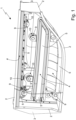
- number 1 denotes as a whole an automotive lighting unit, i.e. a light apparatus adapted to be firmly fixed on the front or rear part of the vehicle body of a motor vehicle, with the function of emitting light signals adapted to signal/indicate the position of the vehicle and/or sudden deceleration of the vehicle and/or turning direction of the vehicle during travel and/or with the function of lighting the area surrounding the vehicle.
- an automotive lighting unit i.e. a light apparatus adapted to be firmly fixed on the front or rear part of the vehicle body of a motor vehicle, with the function of emitting light signals adapted to signal/indicate the position of the vehicle and/or sudden deceleration of the vehicle and/or turning direction of the vehicle during travel and/or with the function of lighting the area surrounding the vehicle.
- the automotive lighting unit 1 is adapted to be fixed on the front or rear part of the vehicle body of a car, van, lorry, motorcycle or other similar motor vehicle, to perform the function of a headlight or taillight.
- the automotive lighting unit 1 may also be used to display luminous signs and/or graphic or alphanumeric symbols.
- automotive lighting unit 1 may also be placed on a lateral side of the car or other similar motor vehicle.
- the automotive lighting unit 1 is also structured so as to be stably recessed in the vehicle body (not shown) and to surface outside of the latter.
- the automotive lighting unit 1 is preferably structured to be stably recessed in the rear part of the vehicle body of a car or other similar motor vehicle.
- the automotive lighting unit 1 is preferably a taillight for cars and the like.
- the automotive lighting unit 1 may also be structured so as to be simply cantilever-fixed to the front, lateral or rear part of the vehicle body (not shown).
- the rear casing 2 is preferably shaped substantially in the form of an, advantageously oblong, basin and/or has a nominal thickness preferably ranging 2 and 4 mm (millimetres).
- the front half-shell 3 is preferably provided with one or more transparent or semi-transparent sectors (namely sectors that allow the passage of visible light), optionally also having different colours from one another, and is rigidly fixed to the rear casing 2 preferably in a substantially fluid-tight manner.
- front half-shell 3 may also include one or more opaque sectors adjoining said transparent or semi-transparent sector or sectors.
- the front half-shell 3 preferably has a shape substantially complementary to the mouth of the rear casing 2, and is fixed to the rear casing 2 along the perimeter rim of said mouth.
- the front half-shell 3 is preferably made of transparent polycarbonate (PC), transparent polymethylmethacrylate (PMMA) or other transparent or semi-transparent polymeric material.
- the front half-shell 3 is moreover directly welded to the rear casing 2 in a known manner, via laser welding, vibration welding or hot-plate welding.
- the/each lighting assembly 4 is preferably arranged inside the rear casing 2 so as to be locally aligned with a corresponding transparent or semi-transparent sector of front half-shell 3, in order to backlight the same transparent or semi-transparent sector of front half-shell 3, preferably separately and independently of the other lighting assemblies 4.
- the lighting assembly 4 or each of the lighting assemblies 4 is furthermore structured so as to emit, on command, a light beam that, once exited from the automotive lighting unit 1 through the front half-shell 3, meets the photometric type-approval standards (colour and light distribution) specified for a given light signal.
- one or some lighting assemblies 4 may also emit a light beam that does not meet or must meet said photometric type-approval standards.
- one or some lighting assemblies 4 may display luminous signs and/or luminous graphic or alphanumeric symbols.
- the lighting assembly or assemblies 4 is/are furthermore electrically-powered lighting assemblies that is/ are adapted to emit light on command and is/are advantageously also entirely contained within the rear casing 2.
- the automotive lighting unit 1 preferably comprises one or more electrically-powered lighting assemblies 4, each of which emits light on command and is arranged inside rear casing 2 so as to backlight, on command, a corresponding transparent or semi-transparent sector of the front half-shell 3, preferably separately and independently from the other lighting assemblies 4.
- the automotive lighting unit 1 comprises a series of internal components, separate and distinct from the rear casing 2 and from the front half-shell 3, that are placed inside the rear casing 2 and preferably contribute to form the lighting assembly or assemblies 4.
- Some of these internal components are substantially rigid and at least partially made of polymeric material opaque to visible light.
- these internal lighting components preferably have a monolithic structure, and are advantageously made via injection moulding.
- one or more of these internal lighting components at least partially made of opaque polymeric material, in the following denoted by the number 5, is/are arranged with the part/portion made of opaque polymeric material resting on the inner surface of the rear casing 2, or rather on the bottom of rear casing 2, at purposely provided contact/support areas 6, and are fixed in a rigid and non-removable manner directly to the rear casing 2 by means of at least one laser welding joint 7 made at said support/contact area or areas 6.
- the/each internal lighting component 5 is provided with at least one part/portion made of opaque polymeric material, is arranged with said part/portion made of opaque polymeric material resting on the inner surface of the rear casing 2 in at least one mutual contact area 6, and is secured in a rigid and non-removable manner to the rear casing 2 by means of at least one laser welding joint 7 made at said contact area 6.
- the contact area 6 between the rear casing 2 and the internal lighting component 5 is furthermore substantially flat.
- the rear casing 2 and the internal lighting component 5 are both made of polymeric material opaque to visible light.
- the contact area 6 between the rear casing 2 and the internal lighting component 5 is formed/defined by two pieces or parts of pieces both made of polymeric material opaque to visible light.
- the internal component or components 5 may also be substantially entirely made of opaque polymeric material.
- the laser welding joint 7 is located inside the perimeter of the contact area 6, straddling the rear casing 2 and the adjacent opaque-polymeric-material portion made of the internal component 5.
- the laser welding joint 7 is moreover substantially spotlike.
- the laser welding joint 7 may also have the shape of a line.
- the outer surface of rear casing 2 has, on the side opposite each laser welding joint 7 made inside the perimeter of the contact area 6 (i.e. each laser welding joint between the rear casing 2 and the adjacent opaque-polymeric-material portion made of the internal lighting component 5), a small, preferably roughly circular-shaped, thickness-reducing recess or depression 8 which is shaped so as to locally, and advantageously also suddenly, reduce the thickness W of the rear casing 2 down to a predefined limit thickness W 0 .
- the value of the limit thickness W 0 is selected so as to allow the laser beam that forms the laser welding joint 7 to pass through the rear casing 2 substantially without causing melting/softening of the polymeric material up to the contact area 6.
- the laser welding joint 7 is therefore located behind said thickness-reducing recess 8.
- the laser welding joint 7 is preferably arranged spaced behind said thickness-reducing recess 8.
- said thickness-reducing recess 8 preferably has a substantially step profile, and advantageously has an extension less than or equal to 30 mm 2 (square millimetres).
- said thickness-reducing recess 8 is preferably shaped/dimensioned so that said limit thickness W 0 is lower than the mean value of the thickness W of the rear casing 2 at the contact area 6, and advantageously also lower than the nominal thickness of the rear casing 2.
- said thickness-reducing recess 8 is preferably shaped/dimensioned so as to locally reduce the thickness of the rear casing 2 by at least 25%.
- the thickness-reducing recess 8 is preferably shaped so as to locally reduce the thickness W of the rear casing 2 by at least 25% advantageously relative to the local mean value and/or the nominal thickness of the rear casing 2.
- the thickness-reducing recess 8 is preferably shaped so as to reduce the thickness W of the rear casing 2 down to a limit thickness W 0 ranging between 1 and 2 mm (millimetres).
- the thickness-reducing recess 8 is preferably shaped so as to reduce the thickness W of the rear casing 2 down to a limit thickness W 0 lower than or equal to 1,5 mm (millimetres).
- the distance that separates the laser welding joint 7 from the bottom of said thickness-reducing recess 8 therefore ranges between 1 mm and 1,5 mm (millimetres).
- the rear casing 2 and the opaque-polymeric-material portion of the internal lighting component 5 are preferably made of respective opaque polymeric materials that have, at least in the neighbourhood of the mutual contact area 6, laser-beam absorption coefficients ⁇ (Beer-Lambert law) different one from the other.
- the contact area 6 between the rear casing 2 and the internal component 5 is formed/defined by two pieces or parts of pieces made of opaque polymeric material, which preferably have laser-beam absorption coefficients ⁇ different in value from one another.
- the difference between the values of the absorption coefficients ⁇ of the two pieces/piece parts is greater than 25%.
- the laser-beam absorption coefficient ⁇ depends on the composition of the polymeric material, the density of the polymeric material, the quantity of carbon black or other additives contained in the polymeric material per unit of volume, and/or the wavelength ⁇ of the laser beam that penetrates into the polymeric material.
- the thickness-reducing recess 8 is preferably located in the piece that is locally made of the opaque polymeric material having the lower laser-beam absorption coefficient ⁇ .
- the rear casing 2 is made of an opaque polymeric material having a laser-beam absorption coefficient ⁇ lower than that of the opaque polymeric material that locally forms the adjacent opaque-polymeric-material part/portion of the internal component 5.
- the opaque polymeric material located between the thickness-reducing recess 8, or rather the bottom of the thickness-reducing recess 8, and the contact area 6 located on the opposite side of the rear casing 2 preferably has an absorption coefficient ⁇ lower than that of the opaque polymeric material that locally forms the internal lighting component 5, or rather the opaque-polymeric-material part/ portion of the internal component 5 that rests on the inner surface of the housing 2 at said contact area 6.
- the rear casing 2 is preferably made of an opaque polymeric material that has a laser-beam absorption coefficient ⁇ lower than that of the opaque polymeric material forming the adjacent opaque-polymeric-material part/portion of the internal lighting component 5, advantageously at least by 30%.
- the absorption coefficient ⁇ of the opaque polymeric material forming the rear casing 2 is preferably at least 40% lower than the absorption coefficient ⁇ of the opaque polymeric material forming the adjacent opaque-polymeric-material portion of the internal component 5.
- the absorption coefficient ⁇ of the polymeric material forming the rear casing 2 preferably ranges between 0, 05 (1/mm) and 1 (1/mm), and more advantageously between 0,1 (1/mm) and 0,2 (1/mm).
- the absorption coefficient ⁇ of the polymeric material forming the opaque-polymeric-material portion made of internal lighting component 5 preferably ranges between 0,2 (1/mm) and 3 (1/mm), and more advantageously between 0,8 (1/mm) and 2 (1/mm).
- the rear casing 2 and the internal component or components 5 may be made of opaque polymeric materials having, at least in the neighbourhood of the mutual contact area 6, absorption coefficients ⁇ substantially equal to one another.
- the rear casing 2 and the internal lighting component 5, or rather the opaque-polymeric-material part/portion of the internal component 5, are furthermore shaped/structured so as to realize, in the mutual contact area 6, a shape coupling.
- the rear casing 2 and the internal lighting component 5, or rather the opaque-polymeric-material portion of the internal component 5, are preferably shaped/structured so as to realize, in the mutual contact area(s) or zone(s) 6, a male-female coupling.
- the/each internal lighting component 5 is preferably provided with one or more protruding fixing pins 9, each of which has at least the distal end made of polymeric material opaque to visible light, extends parallel to a given insertion direction d 0 , and is adapted to arrange its distal end in abutment on the inner surface of rear casing 2 at a respective contact area 6.
- the laser welding joint 7 is preferably located at the distal end of said fixing pin 9.
- the distal end of the/each fixing pin 9 is therefore arranged on the opposite side of the piece, or rather of the rear casing 2, with respect to a respective thickness-reducing recess 8 of rear casing 2.
- the/each fixing pin 9 is preferably moreover adapted to engage a corresponding receiving seat 10, which is preferably substantially cup-shaped, and is realized directly on the rear casing 2, or rather on the inner surface of the rear casing 2, advantageously at the bottom of the same casing.
- the distal end of fixing pin 9, furthermore, is preferably adapted to stably rest on the bottom of the receiving seat 10, and therefore the contact area 6 is preferably located on the bottom of the same receiving seat 10.
- each receiving seat 10 is therefore located on the opposite side of rear casing 2 with respect to a respective thickness-reducing recess 8 of the same rear casing 2.
- the/each receiving seat 10 preferably also has a shape substantially complementary to that of the distal end of the relative fixing pin 9 of internal lighting component 5.
- the internal lighting component or components 5 preferably include, for example, one or more reflector bodies and/or shielding masks and/or corrective lenses and/or diffuser filters and/or coloured lenticular filters and/or reflex reflectors and/or fixing bezels and/or brackets or other auxiliary support structures, which are clearly at least partly made of polymeric material opaque to visible light, and are arranged with the opaque-polymeric-material part resting on the inner surface of the rear casing 2.
- the automotive lighting unit 1 may also comprise one or more cameras and/or one or more photosensitive sensors and/or one or more radar devices and/or one or more LiDAR (acronym of Light Detection and Ranging) instruments and/or other supplementary electronic devices, still housed inside the rigid housing formed/delimited by the rear casing 2 and by the front half-shell 3.
- LiDAR cronym of Light Detection and Ranging
- the internal lighting components 5, moreover, may contribute to form also said supplementary electronic device(s).
- the lighting assembly or assemblies 4 and/or the supplementary electronic device or devices preferably include one or more internal components 5, which have at least one part/portion made of polymeric material opaque to visible light, are arranged with said opaque-polymeric-material part/ portion resting on the inner surface of the rear casing 2 in at least one contact/support area or zone 6, and are rigidly secured in a non-removable manner to the rear casing 2 by means of a laser welding joint 7 made in said contact area 6.
- Production of automotive lighting unit 1 firstly comprises the step of realizing, preferably via injection moulding, a rear casing 2 made of polymeric material opaque to visible light, which has, on its outer surface, one or more thickness-reducing recesses 8, each of which is shaped so as to locally reduce the thickness of rear casing 2 down to said predefined limit thickness W 0 ; and the step of realizing, preferably by injection moulding, at least one internal lighting component 5 having at least a part/portion made of opaque polymeric material.
- production of automotive lighting unit 1 comprises the step of placing the internal lighting component or components 5 inside the rear casing 2, each with its opaque-polymeric-material part/portion resting on the rear casing 2 at a respective contact area 6 which, in turn, is locally aligned and opposed to a respective thickness-reducing recess 8; and then the step of securing the internal lighting component or components 5 directly to the rear casing 2 by making at least one laser welding joint at the/each contact area 6.
- the step of securing the internal lighting component or components 5 directly to the rear casing 2 entails temporarily directing a laser beam r towards the/each thickness-reducing recess 8 of the rear casing 2, so that the laser beam r can, in sequence, reach the bottom of the thickness-reducing recess 8, pass through the rear casing 2 up to reach the contact area 6, and lastly heat the opaque polymeric material located in the neighbourhood of the contact area 6 up to the melting/ softening temperature.
- the laser beam r is adapted to temporarily melt the polymeric material present in the neighbourhood of said contact area 6.
- the laser beam or beams r directed towards the thickness-reducing recess or recesses 8 of the rear casing 2 furthermore has/have a wavelength ⁇ 0 advantageously higher than 400 nm (nanometres) and more conveniently higher than 900 nm (nanometres).
- the step of securing the internal lighting component or components 5 directly to the rear casing 2 entails directing, for a predefined time interval advantageously lower than 30 s (seconds), one or more laser beams r against the outer surface of the rear casing 2, at the thickness-reducing recess or recesses 8 of rear casing 2, so that the laser beam or beam r can reach the bottom of the thickness-reducing recess or recesses 8, pass through the entire thickness of the rear casing 2 at the/each thickness-reducing recess 8, and then reach the support/contact area 6 located on the opposite side of the/each thickness-reducing recess 8.
- the laser beam or beams r heat up the opaque polymeric material located in the neighbourhood of the contact area 6 so as to bring it temporarily to the melting temperature and thus form the laser welding joint 7.
- the laser beam r locally heats up the opaque polymeric material of the internal component 5 to melting temperature. More or less simultaneously, the heat produced is transmitted by conduction also to the polymeric material forming the rear casing 2, thus bringing also the second polymeric material locally to melting temperature.
- the step of placing the internal lighting component or components 5 inside the rear casing 2 preferably entails inserting the fixing pin or pins 9 of the internal component(s) 5 each inside a respective receiving seat 10 realized on the inner surface of the rear casing 2.
- production of automotive lighting unit 1 moreover entails that the opaque polymeric material located between the thickness-reducing recess 8 and the contact area 6 towards which the laser beam r is directed, i.e. the opaque polymeric material that locally forms the rear casing 2, has an absorption coefficient ⁇ (significantly) lower than that of the opaque polymeric material forming the internal lighting component 5, or rather the opaque-polymeric-material part/ portion made of the internal component 5.
- the step of securing the internal lighting component or components 5 directly to the rear casing 2 moreover entails also pressing/compressing the internal component(s) 5 against the rear casing 2 or vice versa, at the respective contact area or areas 6, while the laser beam r brings the opaque polymeric material located in the neighbourhood of the contact area 6 to melting/softening temperature.
- the amount of energy transferred by the laser beam to the polymeric material per unit of length of the optical path increases with the growing of the laser-beam absorption coefficient ⁇ associated with the polymeric material which is crossed by the laser beam.
- the opaque polymeric material behaves almost as if it were semi-transparent to the laser beam.
- this starting section with reduced energy loss is a function of the density and/or composition of the opaque polymeric material crossed, of the absorption coefficient ⁇ of the opaque polymeric material crossed, and/or of the wavelength ⁇ of the laser beam that travels through the opaque polymeric material.
- the laser beam succeeds in passing through the opaque polymeric material giving off to the polymeric material an amount of energy relatively low and such as not to melt or otherwise damage the polymeric material crossed.
- the thickness-reducing recesses 8 on the outer surface of the rear casing 2 are shaped/dimensioned so as to locally reduce the thickness W of the rear casing 2 to a limit thickness W 0 , which is substantially equal to or advantageously lower than the length of said starting section with reduced energy loss.
- the thickness-reducing recesses 8 on the outer surface of rear casing 2 locally reduce the thickness W of the rear casing 2 to values such as to allow the laser beam r that will form the laser welding joint 7, to cross substantially the entire thickness of rear casing 2 advantageously without melting the polymeric material crossed.
- production of automotive lighting unit 1 lastly comprises the step of placing the front half-shell 3 on the mouth of the rear casing 2, and then the step of welding the front half-shell 3 to the rear casing 2 along the perimeter rim of said mouth.
- production of automotive lighting unit 1 preferably entails, before placing the internal lighting component or components 5 inside the rear casing 2 and/or before securing the internal lighting component or components 5 directly to the rear casing 2, the step of placing the rear casing 2 on a workpiece carrying fixture 100, which is structured so as to accommodate and advantageously also retain the rear casing 2 in a given assembly position, in which the mouth of the rear casing 2 is freely accessible from the outside and advantageously also turned upwards.
- the securing the internal lighting components 5 directly to the rear casing 2 by means of the laser welding joints 7 allows to eliminate all, or in any case the majority of, the metal screws currently used to fix the internal components of the automotive lighting unit to its rear casing, with considerable reduction in the resulting weight and production costs.
- the immediate securing of the internal lighting component(s) 5 by means of the laser welding joints 7 allows to eliminate, or at least drastically reduce, the number of shoulders, centring pins and/or snap-on locking tabs usually present inside the rear casing of an automotive lighting unit, with consequent considerable simplification of the structure of the mould used to produce the rear casing 2.
- the thickness-reducing recesses 8 present on the outer surface of the rear casing 2 are easy to produce and eliminate all the operating limits associated with the welding of pieces made of polymeric material opaque to visible light.
- the nominal thickness of the rear casing 2 is chosen so as to give the resulting piece a rigidity and a mechanical resistance appropriate for the use which the automotive lighting unit 1 is intended to.
- the nominal thickness makes the laser welding of internal components made of opaque polymeric material impossible.
- the presence of the thickness-reducing recesses 8 on the rear casing 2 allows to make the welding joints 7 while maintaining an adequate resistance and structural rigidity of the rear casing 2.
- the rear casing 2 may be provided with one or more sectors made of transparent polymeric material, adjoining or surrounded by one or more sectors made of opaque polymeric material preferably having larger dimensions.
- the contact area 6 between the rear casing 2 and the/each internal lighting component 5 is located at the or one of the sectors made of opaque polymeric material that form the rear casing 2.
- the/each fixing pin 9 of the internal component 5 is preferably provided with a longitudinal blind hole 9a, which ends in the proximity of the distal end of said fixing pin 9.
- the fixing pin 9 is made of opaque polymeric material and has, on the bottom of the longitudinal blind hole 36, a small thickness-reducing recess 8, which is shaped so as to reduce, advantageously suddenly, the local thickness of the internal component 5 to said limit thickness W 0 .
- the laser welding joint 7 is located behind the bottom of the thickness-reducing recess 8, at the contact area 6 between the rear casing 2 and the internal component 5.
- the laser welding joint 7 is formed with the aid of a laser beam that travels throughout the whole longitudinal blind hole 9a of fixing pin 9, up to the thickness-reducing recess 8, and then crosses the rear casing 2 where it has the limit thickness W 0 to reach the contact area 6.
- the opaque polymeric material forming the fixing pin 9 that has an absorption coefficient ⁇ lower than that of the opaque polymeric material locally forming the rear casing 2.
- the opaque polymeric material located between the thickness-reducing recess 8, or rather the bottom of the thickness-reducing recess 8, of internal component 5 and the contact area 6 on the opposite side of the internal component 5, or rather of the fixing pin 9, preferably has an absorption coefficient ⁇ lower than that of the opaque polymeric material forming the part of rear casing 2 on which rests the internal lighting component 5, or rather the opaque-polymeric-material part/portion of internal component 5.
Landscapes
- Engineering & Computer Science (AREA)
- Mechanical Engineering (AREA)
- Physics & Mathematics (AREA)
- Health & Medical Sciences (AREA)
- Optics & Photonics (AREA)
- Toxicology (AREA)
- Electromagnetism (AREA)
- General Engineering & Computer Science (AREA)
- Lining Or Joining Of Plastics Or The Like (AREA)
Priority Applications (1)
| Application Number | Priority Date | Filing Date | Title |
|---|---|---|---|
| EP23199291.8A EP4527593A1 (de) | 2023-09-25 | 2023-09-25 | Fahrzeugbeleuchtungseinheit und zugehöriges herstellungsverfahren |
Applications Claiming Priority (1)
| Application Number | Priority Date | Filing Date | Title |
|---|---|---|---|
| EP23199291.8A EP4527593A1 (de) | 2023-09-25 | 2023-09-25 | Fahrzeugbeleuchtungseinheit und zugehöriges herstellungsverfahren |
Publications (1)
| Publication Number | Publication Date |
|---|---|
| EP4527593A1 true EP4527593A1 (de) | 2025-03-26 |
Family
ID=89661692
Family Applications (1)
| Application Number | Title | Priority Date | Filing Date |
|---|---|---|---|
| EP23199291.8A Pending EP4527593A1 (de) | 2023-09-25 | 2023-09-25 | Fahrzeugbeleuchtungseinheit und zugehöriges herstellungsverfahren |
Country Status (1)
| Country | Link |
|---|---|
| EP (1) | EP4527593A1 (de) |
Citations (3)
| Publication number | Priority date | Publication date | Assignee | Title |
|---|---|---|---|---|
| US20040070988A1 (en) * | 2002-10-14 | 2004-04-15 | Guide Corporation | Hermetically sealed lamp housing and method of making |
| US20100238676A1 (en) * | 2009-03-23 | 2010-09-23 | Koito Manufacturing Co., Ltd. | Vehicle lamp |
| WO2021076561A1 (en) * | 2019-10-15 | 2021-04-22 | Covestro Llc | Three part headlamp assembly |
-
2023
- 2023-09-25 EP EP23199291.8A patent/EP4527593A1/de active Pending
Patent Citations (3)
| Publication number | Priority date | Publication date | Assignee | Title |
|---|---|---|---|---|
| US20040070988A1 (en) * | 2002-10-14 | 2004-04-15 | Guide Corporation | Hermetically sealed lamp housing and method of making |
| US20100238676A1 (en) * | 2009-03-23 | 2010-09-23 | Koito Manufacturing Co., Ltd. | Vehicle lamp |
| WO2021076561A1 (en) * | 2019-10-15 | 2021-04-22 | Covestro Llc | Three part headlamp assembly |
Similar Documents
| Publication | Publication Date | Title |
|---|---|---|
| US10507764B2 (en) | Vehicle interior trim assembly configured to form a light pattern having an emblem shape at the front of a trim part such as an air bag cover | |
| US10168021B2 (en) | Light guiding device | |
| EP2548769B1 (de) | Rücklicht für ein Automobil | |
| US11649939B2 (en) | Automotive lighting and/or signaling device and assembly method thereof | |
| EP3463980B1 (de) | Lampenanordnung für ein fahrzeug | |
| KR20210081272A (ko) | 차량 조명 장치 및 관련 제어 방법 | |
| WO2017121944A1 (fr) | Bloc optique comprenant un feu de signalisation doté d'un guide de lumière plat saillant de sa glace extérieure | |
| US7025485B2 (en) | High mount stop lamp with printed circuit board | |
| EP4527593A1 (de) | Fahrzeugbeleuchtungseinheit und zugehöriges herstellungsverfahren | |
| US12181124B2 (en) | Tail light for a motor vehicle | |
| EP4528150A1 (de) | Kraftfahrzeugbeleuchtungsvorrichtung und entsprechendes herstellungsverfahren | |
| EP3297869B1 (de) | Lichtleiter mit verbesserter lichtabdeckung | |
| US11067243B2 (en) | Opaque outer lens with integrated light element | |
| EP3594565B1 (de) | Kraftfahrzeuglicht | |
| EP4527594A1 (de) | Montageverfahren einer fahrzeugbeleuchtungseinheit und maschine zur durchführung des verfahrens | |
| EP4527596A1 (de) | Montageverfahren einer fahrzeugbeleuchtungseinheit und maschine zur durchführung des verfahrens | |
| US20250102129A1 (en) | Assembly Method of an Automotive Lighting Unit and Machine Implementing Such Method | |
| EP4527595A1 (de) | Montageverfahren einer fahrzeugbeleuchtungseinheit und maschine zur durchführung des verfahrens | |
| EP4006407B1 (de) | Beleuchtungs- und/oder signalvorrichtung für kraftfahrzeuge mit einem externen dekorelement und zugehöriges montageverfahren | |
| EP4019832A1 (de) | Beleuchtungsvorrichtung für kraftfahrzeuge | |
| US20020024820A1 (en) | Automotive lamp closeout and method of constructing same | |
| EP3839329B1 (de) | Automotive beleuchtungsvorrichtung | |
| FR3087519A1 (fr) | Module lumineux bi-fonction pour bloc optique d’eclairage et/ou de signalisation de vehicule | |
| WO2003033300A1 (en) | Lighting device for motor vehicles | |
| KR100756699B1 (ko) | 자동차용 사이드마커램프의 설치구조 |
Legal Events
| Date | Code | Title | Description |
|---|---|---|---|
| PUAI | Public reference made under article 153(3) epc to a published international application that has entered the european phase |
Free format text: ORIGINAL CODE: 0009012 |
|
| STAA | Information on the status of an ep patent application or granted ep patent |
Free format text: STATUS: THE APPLICATION HAS BEEN PUBLISHED |
|
| AK | Designated contracting states |
Kind code of ref document: A1 Designated state(s): AL AT BE BG CH CY CZ DE DK EE ES FI FR GB GR HR HU IE IS IT LI LT LU LV MC ME MK MT NL NO PL PT RO RS SE SI SK SM TR |
|
| STAA | Information on the status of an ep patent application or granted ep patent |
Free format text: STATUS: REQUEST FOR EXAMINATION WAS MADE |
|
| 17P | Request for examination filed |
Effective date: 20250924 |