EP4527596A1 - Procédé d'assemblage d'une unité d'éclairage automobile et machine mettant en oeuvre ledit procédé - Google Patents
Procédé d'assemblage d'une unité d'éclairage automobile et machine mettant en oeuvre ledit procédé Download PDFInfo
- Publication number
- EP4527596A1 EP4527596A1 EP23199334.6A EP23199334A EP4527596A1 EP 4527596 A1 EP4527596 A1 EP 4527596A1 EP 23199334 A EP23199334 A EP 23199334A EP 4527596 A1 EP4527596 A1 EP 4527596A1
- Authority
- EP
- European Patent Office
- Prior art keywords
- rear casing
- contact area
- laser beam
- polymeric material
- lighting unit
- Prior art date
- Legal status (The legal status is an assumption and is not a legal conclusion. Google has not performed a legal analysis and makes no representation as to the accuracy of the status listed.)
- Pending
Links
Images




Classifications
-
- B—PERFORMING OPERATIONS; TRANSPORTING
- B29—WORKING OF PLASTICS; WORKING OF SUBSTANCES IN A PLASTIC STATE IN GENERAL
- B29C—SHAPING OR JOINING OF PLASTICS; SHAPING OF MATERIAL IN A PLASTIC STATE, NOT OTHERWISE PROVIDED FOR; AFTER-TREATMENT OF THE SHAPED PRODUCTS, e.g. REPAIRING
- B29C65/00—Joining or sealing of preformed parts, e.g. welding of plastics materials; Apparatus therefor
- B29C65/02—Joining or sealing of preformed parts, e.g. welding of plastics materials; Apparatus therefor by heating, with or without pressure
- B29C65/14—Joining or sealing of preformed parts, e.g. welding of plastics materials; Apparatus therefor by heating, with or without pressure using wave energy, i.e. electromagnetic radiation, or particle radiation
- B29C65/16—Laser beams
- B29C65/1603—Laser beams characterised by the type of electromagnetic radiation
- B29C65/1612—Infrared [IR] radiation, e.g. by infrared lasers
- B29C65/1616—Near infrared radiation [NIR], e.g. by YAG lasers
-
- B—PERFORMING OPERATIONS; TRANSPORTING
- B29—WORKING OF PLASTICS; WORKING OF SUBSTANCES IN A PLASTIC STATE IN GENERAL
- B29C—SHAPING OR JOINING OF PLASTICS; SHAPING OF MATERIAL IN A PLASTIC STATE, NOT OTHERWISE PROVIDED FOR; AFTER-TREATMENT OF THE SHAPED PRODUCTS, e.g. REPAIRING
- B29C65/00—Joining or sealing of preformed parts, e.g. welding of plastics materials; Apparatus therefor
- B29C65/02—Joining or sealing of preformed parts, e.g. welding of plastics materials; Apparatus therefor by heating, with or without pressure
- B29C65/14—Joining or sealing of preformed parts, e.g. welding of plastics materials; Apparatus therefor by heating, with or without pressure using wave energy, i.e. electromagnetic radiation, or particle radiation
- B29C65/16—Laser beams
- B29C65/1629—Laser beams characterised by the way of heating the interface
- B29C65/1635—Laser beams characterised by the way of heating the interface at least passing through one of the parts to be joined, i.e. laser transmission welding
-
- B—PERFORMING OPERATIONS; TRANSPORTING
- B29—WORKING OF PLASTICS; WORKING OF SUBSTANCES IN A PLASTIC STATE IN GENERAL
- B29C—SHAPING OR JOINING OF PLASTICS; SHAPING OF MATERIAL IN A PLASTIC STATE, NOT OTHERWISE PROVIDED FOR; AFTER-TREATMENT OF THE SHAPED PRODUCTS, e.g. REPAIRING
- B29C65/00—Joining or sealing of preformed parts, e.g. welding of plastics materials; Apparatus therefor
- B29C65/02—Joining or sealing of preformed parts, e.g. welding of plastics materials; Apparatus therefor by heating, with or without pressure
- B29C65/14—Joining or sealing of preformed parts, e.g. welding of plastics materials; Apparatus therefor by heating, with or without pressure using wave energy, i.e. electromagnetic radiation, or particle radiation
- B29C65/16—Laser beams
- B29C65/1629—Laser beams characterised by the way of heating the interface
- B29C65/1645—Laser beams characterised by the way of heating the interface heating both sides of the joint, e.g. by using two lasers or a split beam
-
- B—PERFORMING OPERATIONS; TRANSPORTING
- B29—WORKING OF PLASTICS; WORKING OF SUBSTANCES IN A PLASTIC STATE IN GENERAL
- B29C—SHAPING OR JOINING OF PLASTICS; SHAPING OF MATERIAL IN A PLASTIC STATE, NOT OTHERWISE PROVIDED FOR; AFTER-TREATMENT OF THE SHAPED PRODUCTS, e.g. REPAIRING
- B29C65/00—Joining or sealing of preformed parts, e.g. welding of plastics materials; Apparatus therefor
- B29C65/02—Joining or sealing of preformed parts, e.g. welding of plastics materials; Apparatus therefor by heating, with or without pressure
- B29C65/14—Joining or sealing of preformed parts, e.g. welding of plastics materials; Apparatus therefor by heating, with or without pressure using wave energy, i.e. electromagnetic radiation, or particle radiation
- B29C65/16—Laser beams
- B29C65/1629—Laser beams characterised by the way of heating the interface
- B29C65/1664—Laser beams characterised by the way of heating the interface making use of several radiators
- B29C65/1667—Laser beams characterised by the way of heating the interface making use of several radiators at the same time, i.e. simultaneous laser welding
-
- B—PERFORMING OPERATIONS; TRANSPORTING
- B29—WORKING OF PLASTICS; WORKING OF SUBSTANCES IN A PLASTIC STATE IN GENERAL
- B29C—SHAPING OR JOINING OF PLASTICS; SHAPING OF MATERIAL IN A PLASTIC STATE, NOT OTHERWISE PROVIDED FOR; AFTER-TREATMENT OF THE SHAPED PRODUCTS, e.g. REPAIRING
- B29C65/00—Joining or sealing of preformed parts, e.g. welding of plastics materials; Apparatus therefor
- B29C65/02—Joining or sealing of preformed parts, e.g. welding of plastics materials; Apparatus therefor by heating, with or without pressure
- B29C65/14—Joining or sealing of preformed parts, e.g. welding of plastics materials; Apparatus therefor by heating, with or without pressure using wave energy, i.e. electromagnetic radiation, or particle radiation
- B29C65/16—Laser beams
- B29C65/1687—Laser beams making use of light guides
-
- B—PERFORMING OPERATIONS; TRANSPORTING
- B29—WORKING OF PLASTICS; WORKING OF SUBSTANCES IN A PLASTIC STATE IN GENERAL
- B29C—SHAPING OR JOINING OF PLASTICS; SHAPING OF MATERIAL IN A PLASTIC STATE, NOT OTHERWISE PROVIDED FOR; AFTER-TREATMENT OF THE SHAPED PRODUCTS, e.g. REPAIRING
- B29C65/00—Joining or sealing of preformed parts, e.g. welding of plastics materials; Apparatus therefor
- B29C65/78—Means for handling the parts to be joined, e.g. for making containers or hollow articles, e.g. means for handling sheets, plates, web-like materials, tubular articles, hollow articles or elements to be joined therewith; Means for discharging the joined articles from the joining apparatus
- B29C65/7841—Holding or clamping means for handling purposes
-
- B—PERFORMING OPERATIONS; TRANSPORTING
- B29—WORKING OF PLASTICS; WORKING OF SUBSTANCES IN A PLASTIC STATE IN GENERAL
- B29C—SHAPING OR JOINING OF PLASTICS; SHAPING OF MATERIAL IN A PLASTIC STATE, NOT OTHERWISE PROVIDED FOR; AFTER-TREATMENT OF THE SHAPED PRODUCTS, e.g. REPAIRING
- B29C66/00—General aspects of processes or apparatus for joining preformed parts
- B29C66/01—General aspects dealing with the joint area or with the area to be joined
- B29C66/05—Particular design of joint configurations
- B29C66/10—Particular design of joint configurations particular design of the joint cross-sections
- B29C66/11—Joint cross-sections comprising a single joint-segment, i.e. one of the parts to be joined comprising a single joint-segment in the joint cross-section
- B29C66/112—Single lapped joints
- B29C66/1122—Single lap to lap joints, i.e. overlap joints
-
- B—PERFORMING OPERATIONS; TRANSPORTING
- B29—WORKING OF PLASTICS; WORKING OF SUBSTANCES IN A PLASTIC STATE IN GENERAL
- B29C—SHAPING OR JOINING OF PLASTICS; SHAPING OF MATERIAL IN A PLASTIC STATE, NOT OTHERWISE PROVIDED FOR; AFTER-TREATMENT OF THE SHAPED PRODUCTS, e.g. REPAIRING
- B29C66/00—General aspects of processes or apparatus for joining preformed parts
- B29C66/01—General aspects dealing with the joint area or with the area to be joined
- B29C66/05—Particular design of joint configurations
- B29C66/10—Particular design of joint configurations particular design of the joint cross-sections
- B29C66/12—Joint cross-sections combining only two joint-segments; Tongue and groove joints; Tenon and mortise joints; Stepped joint cross-sections
- B29C66/126—Tenon and mortise joints
-
- B—PERFORMING OPERATIONS; TRANSPORTING
- B29—WORKING OF PLASTICS; WORKING OF SUBSTANCES IN A PLASTIC STATE IN GENERAL
- B29C—SHAPING OR JOINING OF PLASTICS; SHAPING OF MATERIAL IN A PLASTIC STATE, NOT OTHERWISE PROVIDED FOR; AFTER-TREATMENT OF THE SHAPED PRODUCTS, e.g. REPAIRING
- B29C66/00—General aspects of processes or apparatus for joining preformed parts
- B29C66/01—General aspects dealing with the joint area or with the area to be joined
- B29C66/05—Particular design of joint configurations
- B29C66/20—Particular design of joint configurations particular design of the joint lines, e.g. of the weld lines
- B29C66/21—Particular design of joint configurations particular design of the joint lines, e.g. of the weld lines said joint lines being formed by a single dot or dash or by several dots or dashes, i.e. spot joining or spot welding
-
- B—PERFORMING OPERATIONS; TRANSPORTING
- B29—WORKING OF PLASTICS; WORKING OF SUBSTANCES IN A PLASTIC STATE IN GENERAL
- B29C—SHAPING OR JOINING OF PLASTICS; SHAPING OF MATERIAL IN A PLASTIC STATE, NOT OTHERWISE PROVIDED FOR; AFTER-TREATMENT OF THE SHAPED PRODUCTS, e.g. REPAIRING
- B29C66/00—General aspects of processes or apparatus for joining preformed parts
- B29C66/01—General aspects dealing with the joint area or with the area to be joined
- B29C66/347—General aspects dealing with the joint area or with the area to be joined using particular temperature distributions or gradients; using particular heat distributions or gradients
- B29C66/3474—General aspects dealing with the joint area or with the area to be joined using particular temperature distributions or gradients; using particular heat distributions or gradients perpendicular to the plane of the joint
-
- B—PERFORMING OPERATIONS; TRANSPORTING
- B29—WORKING OF PLASTICS; WORKING OF SUBSTANCES IN A PLASTIC STATE IN GENERAL
- B29C—SHAPING OR JOINING OF PLASTICS; SHAPING OF MATERIAL IN A PLASTIC STATE, NOT OTHERWISE PROVIDED FOR; AFTER-TREATMENT OF THE SHAPED PRODUCTS, e.g. REPAIRING
- B29C66/00—General aspects of processes or apparatus for joining preformed parts
- B29C66/50—General aspects of joining tubular articles; General aspects of joining long products, i.e. bars or profiled elements; General aspects of joining single elements to tubular articles, hollow articles or bars; General aspects of joining several hollow-preforms to form hollow or tubular articles
- B29C66/51—Joining tubular articles, profiled elements or bars; Joining single elements to tubular articles, hollow articles or bars; Joining several hollow-preforms to form hollow or tubular articles
- B29C66/53—Joining single elements to tubular articles, hollow articles or bars
- B29C66/532—Joining single elements to the wall of tubular articles, hollow articles or bars
-
- B—PERFORMING OPERATIONS; TRANSPORTING
- B29—WORKING OF PLASTICS; WORKING OF SUBSTANCES IN A PLASTIC STATE IN GENERAL
- B29C—SHAPING OR JOINING OF PLASTICS; SHAPING OF MATERIAL IN A PLASTIC STATE, NOT OTHERWISE PROVIDED FOR; AFTER-TREATMENT OF THE SHAPED PRODUCTS, e.g. REPAIRING
- B29C66/00—General aspects of processes or apparatus for joining preformed parts
- B29C66/50—General aspects of joining tubular articles; General aspects of joining long products, i.e. bars or profiled elements; General aspects of joining single elements to tubular articles, hollow articles or bars; General aspects of joining several hollow-preforms to form hollow or tubular articles
- B29C66/51—Joining tubular articles, profiled elements or bars; Joining single elements to tubular articles, hollow articles or bars; Joining several hollow-preforms to form hollow or tubular articles
- B29C66/54—Joining several hollow-preforms, e.g. half-shells, to form hollow articles, e.g. for making balls, containers; Joining several hollow-preforms, e.g. half-cylinders, to form tubular articles
-
- B—PERFORMING OPERATIONS; TRANSPORTING
- B29—WORKING OF PLASTICS; WORKING OF SUBSTANCES IN A PLASTIC STATE IN GENERAL
- B29C—SHAPING OR JOINING OF PLASTICS; SHAPING OF MATERIAL IN A PLASTIC STATE, NOT OTHERWISE PROVIDED FOR; AFTER-TREATMENT OF THE SHAPED PRODUCTS, e.g. REPAIRING
- B29C66/00—General aspects of processes or apparatus for joining preformed parts
- B29C66/50—General aspects of joining tubular articles; General aspects of joining long products, i.e. bars or profiled elements; General aspects of joining single elements to tubular articles, hollow articles or bars; General aspects of joining several hollow-preforms to form hollow or tubular articles
- B29C66/61—Joining from or joining on the inside
-
- B—PERFORMING OPERATIONS; TRANSPORTING
- B29—WORKING OF PLASTICS; WORKING OF SUBSTANCES IN A PLASTIC STATE IN GENERAL
- B29C—SHAPING OR JOINING OF PLASTICS; SHAPING OF MATERIAL IN A PLASTIC STATE, NOT OTHERWISE PROVIDED FOR; AFTER-TREATMENT OF THE SHAPED PRODUCTS, e.g. REPAIRING
- B29C66/00—General aspects of processes or apparatus for joining preformed parts
- B29C66/70—General aspects of processes or apparatus for joining preformed parts characterised by the composition, physical properties or the structure of the material of the parts to be joined; Joining with non-plastics material
- B29C66/73—General aspects of processes or apparatus for joining preformed parts characterised by the composition, physical properties or the structure of the material of the parts to be joined; Joining with non-plastics material characterised by the intensive physical properties of the material of the parts to be joined, by the optical properties of the material of the parts to be joined, by the extensive physical properties of the parts to be joined, by the state of the material of the parts to be joined or by the material of the parts to be joined being a thermoplastic or a thermoset
- B29C66/735—General aspects of processes or apparatus for joining preformed parts characterised by the composition, physical properties or the structure of the material of the parts to be joined; Joining with non-plastics material characterised by the intensive physical properties of the material of the parts to be joined, by the optical properties of the material of the parts to be joined, by the extensive physical properties of the parts to be joined, by the state of the material of the parts to be joined or by the material of the parts to be joined being a thermoplastic or a thermoset characterised by the extensive physical properties of the parts to be joined
- B29C66/7352—Thickness, e.g. very thin
-
- B—PERFORMING OPERATIONS; TRANSPORTING
- B29—WORKING OF PLASTICS; WORKING OF SUBSTANCES IN A PLASTIC STATE IN GENERAL
- B29C—SHAPING OR JOINING OF PLASTICS; SHAPING OF MATERIAL IN A PLASTIC STATE, NOT OTHERWISE PROVIDED FOR; AFTER-TREATMENT OF THE SHAPED PRODUCTS, e.g. REPAIRING
- B29C66/00—General aspects of processes or apparatus for joining preformed parts
- B29C66/80—General aspects of machine operations or constructions and parts thereof
- B29C66/81—General aspects of the pressing elements, i.e. the elements applying pressure on the parts to be joined in the area to be joined, e.g. the welding jaws or clamps
- B29C66/814—General aspects of the pressing elements, i.e. the elements applying pressure on the parts to be joined in the area to be joined, e.g. the welding jaws or clamps characterised by the design of the pressing elements, e.g. of the welding jaws or clamps
- B29C66/8141—General aspects of the pressing elements, i.e. the elements applying pressure on the parts to be joined in the area to be joined, e.g. the welding jaws or clamps characterised by the design of the pressing elements, e.g. of the welding jaws or clamps characterised by the surface geometry of the part of the pressing elements, e.g. welding jaws or clamps, coming into contact with the parts to be joined
- B29C66/81431—General aspects of the pressing elements, i.e. the elements applying pressure on the parts to be joined in the area to be joined, e.g. the welding jaws or clamps characterised by the design of the pressing elements, e.g. of the welding jaws or clamps characterised by the surface geometry of the part of the pressing elements, e.g. welding jaws or clamps, coming into contact with the parts to be joined comprising a single cavity, e.g. a groove
-
- B—PERFORMING OPERATIONS; TRANSPORTING
- B29—WORKING OF PLASTICS; WORKING OF SUBSTANCES IN A PLASTIC STATE IN GENERAL
- B29C—SHAPING OR JOINING OF PLASTICS; SHAPING OF MATERIAL IN A PLASTIC STATE, NOT OTHERWISE PROVIDED FOR; AFTER-TREATMENT OF THE SHAPED PRODUCTS, e.g. REPAIRING
- B29C66/00—General aspects of processes or apparatus for joining preformed parts
- B29C66/80—General aspects of machine operations or constructions and parts thereof
- B29C66/83—General aspects of machine operations or constructions and parts thereof characterised by the movement of the joining or pressing tools
- B29C66/832—Reciprocating joining or pressing tools
- B29C66/8322—Joining or pressing tools reciprocating along one axis
-
- B—PERFORMING OPERATIONS; TRANSPORTING
- B29—WORKING OF PLASTICS; WORKING OF SUBSTANCES IN A PLASTIC STATE IN GENERAL
- B29C—SHAPING OR JOINING OF PLASTICS; SHAPING OF MATERIAL IN A PLASTIC STATE, NOT OTHERWISE PROVIDED FOR; AFTER-TREATMENT OF THE SHAPED PRODUCTS, e.g. REPAIRING
- B29C66/00—General aspects of processes or apparatus for joining preformed parts
- B29C66/80—General aspects of machine operations or constructions and parts thereof
- B29C66/84—Specific machine types or machines suitable for specific applications
- B29C66/843—Machines for making separate joints at the same time in different planes; Machines for making separate joints at the same time mounted in parallel or in series
- B29C66/8432—Machines for making separate joints at the same time mounted in parallel or in series
-
- B—PERFORMING OPERATIONS; TRANSPORTING
- B29—WORKING OF PLASTICS; WORKING OF SUBSTANCES IN A PLASTIC STATE IN GENERAL
- B29C—SHAPING OR JOINING OF PLASTICS; SHAPING OF MATERIAL IN A PLASTIC STATE, NOT OTHERWISE PROVIDED FOR; AFTER-TREATMENT OF THE SHAPED PRODUCTS, e.g. REPAIRING
- B29C65/00—Joining or sealing of preformed parts, e.g. welding of plastics materials; Apparatus therefor
- B29C65/02—Joining or sealing of preformed parts, e.g. welding of plastics materials; Apparatus therefor by heating, with or without pressure
- B29C65/14—Joining or sealing of preformed parts, e.g. welding of plastics materials; Apparatus therefor by heating, with or without pressure using wave energy, i.e. electromagnetic radiation, or particle radiation
- B29C65/16—Laser beams
- B29C65/1629—Laser beams characterised by the way of heating the interface
- B29C65/1635—Laser beams characterised by the way of heating the interface at least passing through one of the parts to be joined, i.e. laser transmission welding
- B29C65/1638—Laser beams characterised by the way of heating the interface at least passing through one of the parts to be joined, i.e. laser transmission welding focusing the laser beam on the interface
-
- B—PERFORMING OPERATIONS; TRANSPORTING
- B29—WORKING OF PLASTICS; WORKING OF SUBSTANCES IN A PLASTIC STATE IN GENERAL
- B29C—SHAPING OR JOINING OF PLASTICS; SHAPING OF MATERIAL IN A PLASTIC STATE, NOT OTHERWISE PROVIDED FOR; AFTER-TREATMENT OF THE SHAPED PRODUCTS, e.g. REPAIRING
- B29C66/00—General aspects of processes or apparatus for joining preformed parts
- B29C66/70—General aspects of processes or apparatus for joining preformed parts characterised by the composition, physical properties or the structure of the material of the parts to be joined; Joining with non-plastics material
- B29C66/73—General aspects of processes or apparatus for joining preformed parts characterised by the composition, physical properties or the structure of the material of the parts to be joined; Joining with non-plastics material characterised by the intensive physical properties of the material of the parts to be joined, by the optical properties of the material of the parts to be joined, by the extensive physical properties of the parts to be joined, by the state of the material of the parts to be joined or by the material of the parts to be joined being a thermoplastic or a thermoset
- B29C66/739—General aspects of processes or apparatus for joining preformed parts characterised by the composition, physical properties or the structure of the material of the parts to be joined; Joining with non-plastics material characterised by the intensive physical properties of the material of the parts to be joined, by the optical properties of the material of the parts to be joined, by the extensive physical properties of the parts to be joined, by the state of the material of the parts to be joined or by the material of the parts to be joined being a thermoplastic or a thermoset characterised by the material of the parts to be joined being a thermoplastic or a thermoset
- B29C66/7392—General aspects of processes or apparatus for joining preformed parts characterised by the composition, physical properties or the structure of the material of the parts to be joined; Joining with non-plastics material characterised by the intensive physical properties of the material of the parts to be joined, by the optical properties of the material of the parts to be joined, by the extensive physical properties of the parts to be joined, by the state of the material of the parts to be joined or by the material of the parts to be joined being a thermoplastic or a thermoset characterised by the material of the parts to be joined being a thermoplastic or a thermoset characterised by the material of at least one of the parts being a thermoplastic
- B29C66/73921—General aspects of processes or apparatus for joining preformed parts characterised by the composition, physical properties or the structure of the material of the parts to be joined; Joining with non-plastics material characterised by the intensive physical properties of the material of the parts to be joined, by the optical properties of the material of the parts to be joined, by the extensive physical properties of the parts to be joined, by the state of the material of the parts to be joined or by the material of the parts to be joined being a thermoplastic or a thermoset characterised by the material of the parts to be joined being a thermoplastic or a thermoset characterised by the material of at least one of the parts being a thermoplastic characterised by the materials of both parts being thermoplastics
-
- B—PERFORMING OPERATIONS; TRANSPORTING
- B29—WORKING OF PLASTICS; WORKING OF SUBSTANCES IN A PLASTIC STATE IN GENERAL
- B29K—INDEXING SCHEME ASSOCIATED WITH SUBCLASSES B29B, B29C OR B29D, RELATING TO MOULDING MATERIALS OR TO MATERIALS FOR MOULDS, REINFORCEMENTS, FILLERS OR PREFORMED PARTS, e.g. INSERTS
- B29K2995/00—Properties of moulding materials, reinforcements, fillers, preformed parts or moulds
- B29K2995/0018—Properties of moulding materials, reinforcements, fillers, preformed parts or moulds having particular optical properties, e.g. fluorescent or phosphorescent
- B29K2995/0026—Transparent
- B29K2995/0027—Transparent for light outside the visible spectrum
-
- B—PERFORMING OPERATIONS; TRANSPORTING
- B29—WORKING OF PLASTICS; WORKING OF SUBSTANCES IN A PLASTIC STATE IN GENERAL
- B29L—INDEXING SCHEME ASSOCIATED WITH SUBCLASS B29C, RELATING TO PARTICULAR ARTICLES
- B29L2031/00—Other particular articles
- B29L2031/30—Vehicles, e.g. ships or aircraft, or body parts thereof
- B29L2031/3055—Cars
-
- B—PERFORMING OPERATIONS; TRANSPORTING
- B29—WORKING OF PLASTICS; WORKING OF SUBSTANCES IN A PLASTIC STATE IN GENERAL
- B29L—INDEXING SCHEME ASSOCIATED WITH SUBCLASS B29C, RELATING TO PARTICULAR ARTICLES
- B29L2031/00—Other particular articles
- B29L2031/747—Lightning equipment
Definitions
- the present invention concerns an assembly method of an automotive lighting unit and a machine implementing said method.
- the present invention relates to a method and a machine for fixing components made of opaque plastic material inside the rear casing of a headlight or taillight for cars and similar motor vehicles. Uso to which the following disclosure will explicitly refer without however losing generality.
- a headlight or taillight for cars and similar motor vehicles is conventionally a lighting apparatus specifically structured to be placed in the front, rear or lateral part of the vehicle, and performs the function of lighting the area surrounding the vehicle and/or the function of signalling the position of the vehicle, sudden deceleration of the vehicle and/or turning direction of the vehicle, in compliance with given photometric type-approval standards.
- the majority of taillights for cars and similar motor vehicles usually comprise: a rear casing with substantially rigid and opaque structure, which is substantially basin-shaped and is structured so as to be stably recessed in a purposely provided compartment realized in the rear part of the vehicle body; a front half-shell with substantially rigid and transparent structure, separate and distinct from the rear casing, which has a shape complementary to the mouth of the rear casing and is arranged to close the mouth of the rear casing, usually so as to surface outside of the vehicle body; and a series of electrically-powered lighting assemblies, which are located inside the rear casing, each one immediately beneath a corresponding transparent or semi-transparent sector of the front half-shell, so as to selectively backlight the overlying transparent or semi-transparent sector of the front half-shell.
- each transparent or semi-transparent sector of the front half-shell is also uniquely associated to a specific light signal, hence the various lighting assemblies inside the hollow housing formed/delimited by the front half-shell and by the rear casing are structured so as to emit, on command, a light beam which, once exited from the lighting unit through the corresponding transparent or semi-transparent sector of the half-shell, meets the photometric type-approval standards (light colour and distribution) specified for said light signal.
- both the rear casing and the front half-shell have a monolithic structure and are made of polymeric material by injection moulding.
- the rear casing is made entirely of opaque polymeric material
- the front half-shell is made entirely, or almost entirely, of transparent and/or semi-transparent polymeric material.
- the front half-shell is joined in a non-removable manner to the rear casing via laser welding along the entire perimeter rim of the mouth of the rear casing.
- the lighting assemblies that are placed inside the rear casing usually use a series of LEDs (acronym of Light Emitting Diode) as light sources, and generally also include one or more reflector bodies that reflect the light produced by the LEDs towards the facing transparent or semi-transparent sector of the front half-shell, and/or one or more light-guide bodies that collect the light produced by the LEDs and channel it by total internal reflection to the facing transparent or semi-transparent sector of the front half-shell.
- LEDs ancronym of Light Emitting Diode
- these lighting assemblies usually also comprise filters, corrective optics, shielding masks and/or other active and/or passive optical devices, which are able to adapt the light beam emitted by the various LEDs to the photometric and aesthetic requirements associated with automotive use.
- the majority of the taillights described above are additionally provided with internal bezels, brackets and/or other support members that fit into the rear casing, or more simply rest on the inner surface of the rear casing, and are structured to support the printed circuit board(s) that accommodate the LEDs, the reflector body or bodies, the light-guide body or bodies and/or the other active and/or passive optical devices that contribute in forming each lighting assembly, and/or the electric wiring that powers and/or controls the various lighting assemblies.
- the majority of the components that contribute in forming the lighting assemblies of the taillight and the majority of the internal support members are made of opaque polymeric material and are firmly fixed to the rear casing by means of a series of self-threading metal screws, the majority of which are inserted in pass-through manner in the rear casing from the outside towards the inside of the taillight, so as to arrange the head of the screw in abutment on the outer surface of the casing.
- some internal components of the automotive lighting unit can be retained inside the casing also by a series of shoulders, centring pins and/or snap-on locking tabs made inside the rear casing.
- centring and/or snap-on locking systems are used only during the assembly of the lighting unit, because they are generally not able to withstand the mechanical vibrations to which automotive lighting units are normally subjected to during use.
- the present-day assembly lines for automotive lighting units are therefore currently provided with a series of automatic or semi-automatic screwdrivers, which enable the operators working on the assembly line to place and screw the self-threading screws into the rear casing as rapidly as possible.
- the self-threading screws make the assembly of the taillight relatively laborious and also significantly affect the overall weight and cost of the light. Being made of metal, in fact, the self-threading screws are some of the most costly components of the lighting unit.
- Aim of the present invention is to eliminate or in any case minimize the use of self-threading screws, so as to simplify and speed up the assembly of automotive lighting units.
- an assembly method of an automotive lighting unit as defined in Claim 1 and preferably, though not necessarily, in any one of the dependent claims.
- an automotive-lighting-units assembly machine as defined in Claim 13 and preferably, though not necessarily, in any one of the dependent claims.
- an automotive lighting unit as defined in Claim 16 and preferably, though not necessarily, in any one of the dependent claims.
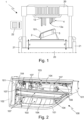
- number 1 denotes as a whole an automotive-lighting-units assembly machine, which is adapted to carry out the laser welding of plastic parts.
- the machine 1 is specifically structured to laser-weld, directly on the rear casing of an automotive lighting unit 100, at least part of the components made of opaque polymeric material, which are located inside the rear casing and contribute in forming the automotive lighting unit 100.
- autonomous lighting unit indicates a lighting apparatus structured to be firmly fixed on the front or rear part of the vehicle body of a motor vehicle (not illustrated), with the function of emitting light signals adapted to signal/ indicate the position of the vehicle and/or the sudden deceleration of the vehicle and/or the turning direction of the vehicle during travel and/or with the function of lighting the area surrounding the vehicle.
- the automotive lighting unit 100 is adapted to be fixed on the front or rear part of the vehicle body of a car, van, lorry, motorcycle or other similar motor vehicle, to perform the function of a headlight or taillight.
- the automotive lighting unit 100 may also be used to display luminous signs and/or graphic or alphanumeric symbols.
- automotive lighting unit 100 may also be placed on a lateral side of the car or other similar motor vehicle.
- the automotive lighting unit 100 is moreover structured so as to be stably recessed into the vehicle body (not illustrated) and to surface outside of the latter.
- the automotive lighting unit 100 comprises: a substantially rigid rear casing 101, which is concave in shape and is adapted to be firmly fixed to the vehicle body (not illustrated), preferably inside a seat specifically provided in said body; and a substantially rigid and at least partially transparent, front half-shell 102, separate and distinct from the rear casing 101, which has a roughly lenticular shape/structure and is firmly fixed to the rear casing 101 to at least partially close the mouth of the latter, so as to form/delimit, together with the rear casing 101, an internally hollow rigid housing.
- the rear casing 101 is preferably shaped substantially in the form of an, advantageously oblong, basin and/or has a nominal thickness preferably between 1 and 4 mm (millimetres).
- the rear casing 101 has a structure which is overall opaque to visible light and is at least partially made of polymeric material. In other words, the rear casing 101 is at least partially made of opaque polymeric material.
- the front half-shell 102 has a structure which is overall transparent to visible light and is preferably at least partially made of transparent polymeric material.
- the front half-shell 102 is furthermore shaped/ structured so as to substantially entirely close the mouth of the rear casing 101.
- the front half-shell 102 is preferably shaped so as to form/delimit, together with the rear casing 101, a rigid, closed and internally hollow housing.
- the front half-shell 102 is furthermore shaped and structured so as to surface outside of the vehicle body.
- the automotive lighting unit 100 additionally comprises a series of internal lighting components, which contribute in forming one or more lighting assemblies 103, each of which is located inside the rear casing 101 and is adapted to backlight the front half-shell 102.
- the lighting assembly/assemblies 103 is/are furthermore electrically-powered lighting assemblies which is/ are adapted to emit light on command and is/are advantageously also entirely contained inside the rear casing 101.
- the automotive lighting unit 100 preferably comprises one or more electrically-powered lighting assemblies 103, each of which emits light on command and is located inside the rear casing 101 so as to selectively backlight the front half-shell 102.
- the rear casing 101 preferably has a monolithic structure, and is preferably made entirely or almost entirely of polymeric material opaque to visible light, advantageously by injection moulding.
- the front half-shell 102 preferably has a monolithic structure, and is preferably entirely or almost entirely made of polymeric material transparent to visible light, advantageously by injection moulding.
- the front half-shell 102 preferably has a shape substantially complementary to the mouth of rear casing 101, and is preferably firmly fixed to the rear casing 101 along the perimeter rim of said mouth.
- the front half-shell 102 is furthermore rigidly fixed to the rear casing 101 in a substantially fluid-tight manner.
- the front half-shell 102 is preferably fixed in a non-removable manner to the rear casing 101 via welding.
- the front half-shell 102 is preferably fixed in a non-removable manner to the rear casing 101 via a welding bead that extends along the perimeter rim of the mouth of rear casing 101, advantageously substantially seamlessly.
- the automotive lighting unit 100 is preferably structured so as to be recessed in the rear part of the vehicle body of a car or other similar motor vehicle.
- the automotive lighting unit 100 is preferably a taillight for cars and the like.
- automotive lighting unit 100 may also be a headlight for cars and the like.
- the automotive lighting unit 100 may also be structured so as to be simply cantilever-fixed on the front, lateral or rear part of the vehicle body (not illustrated).
- the rear casing 101 is preferably made entirely or almost entirely of a thermoplastic polymer opaque to visible light.
- the rear casing 101 is preferably made entirely or almost entirely of acrylonitrile-butadiene-styrene (ABS) or other polymeric material filled with carbon black or other opacifying pigment.
- ABS acrylonitrile-butadiene-styrene
- the front half-shell 102 is provided with one or more transparent or semi-transparent sectors (i.e. sectors that allow the passage of visible light), optionally also having different colours from one another, and is preferably made entirely or almost entirely of a transparent thermoplastic polymer.
- the front half-shell 102 is preferably made of transparent polycarbonate (PC), transparent polymethylmethacrylate (PMMA) or other transparent or semi-transparent polymeric material.
- front half-shell 102 may also include one or more opaque sectors adjoining said transparent or semi-transparent sector(s) .
- the front half-shell 102 is furthermore welded directly to the rear casing 101 in known manner, via laser welding, vibration welding or hot-plate welding.
- the/each lighting assembly 103 is preferably located inside the rear casing 101 so as to be locally aligned to a corresponding transparent or semi-transparent sector of the front half-shell 102, thus to selectively backlight the same transparent or semi-transparent sector of the front half-shell 102, preferably separately and independently of the other lighting assemblies 103 of the automotive lighting unit 100.
- the/each of the lighting assemblies 103 is furthermore structured so as to emit, on command, a light beam which, once exited from the automotive lighting unit 100 through the front half-shell 102, meets the photometric type-approval standards (light colour and distribution) specified for a given light signal.
- one or some lighting assemblies 103 may also emit a light beam that does not meet or must meet said photometric type-approval standards.
- one or some lighting assemblies 103 may be used to display luminous signs and/or luminous graphic or alphanumeric symbols.
- the automotive lighting unit 100 is provided with a plurality of internal lighting components, separate and distinct from the rear casing 101 and from the front half-shell 102, which preferably contribute in forming the lighting assembly/ assemblies 103.
- Some of these internal lighting components are substantially rigid and at least partially made of polymeric material opaque to visible light.
- one or more of these internal lighting components at least partially made of opaque polymeric material, in the following denoted by number 104, is/are arranged with the part made of opaque polymeric material resting on the inner surface of the rear casing 101 at respective mutual contact areas 105, and are rigidly and non-removably fixed directly to the rear casing 101 by means of at least one laser welding joint 106 made at said mutual contact area(s) 105.
- the contact area 105 between the rear casing 101 and the internal component 104 is furthermore substantially flat.
- the laser welding joint 106 is preferably substantially spotlike and/or has an extension less than or equal to 100 mm 2 (square millimetres). Clearly the laser welding joint 106 106 may also have the shape of a line.
- each internal component 104 is arranged with the part made of opaque polymeric material resting on the inner surface of the rear casing 101 in at least one contact area or zone 105, and is rigidly and non-removably secured to the rear casing 101 by means of at least one laser welding joint 106 made at said contact area or zone 105.
- the rear casing 101 and the internal component 104 are both made of polymeric material opaque to visible light.
- the laser welding joint 106 is made in the mutual contact area 105, straddling a portion of the rear casing 101 and the adjacent portion of the internal component 104, both made of opaque polymeric material.
- the internal component or components 104 preferably has/have a monolithic structure, and is/are preferably made entirely of opaque polymeric material, advantageously by injection moulding.
- the internal component or components 104 is/are preferably made entirely of an opaque thermoplastic polymer.
- the rear casing 101 and the internal component or components 104 are preferably made of respective opaque polymeric materials which have, at least in the neighbourhood of the mutual contact area 105, different laser beam absorption coefficients ⁇ (Beer-Lambert law).
- the contact area 105 between the rear casing 101 and the internal component 104 is formed/defined by two pieces or portions made of polymeric material opaque to visible light, which preferably have different laser beam absorption coefficients ⁇ .
- the difference between the absorption coefficients ⁇ of the two opaque polymeric materials is preferably higher than 35% of the absorption coefficient ⁇ with higher value.
- the absorption coefficient ⁇ depends on the composition of the polymeric material, the density of the polymeric material, the quantity of carbon black or other additive contained in the polymeric material per unit of volume, and/or the wavelength ⁇ of the laser beam that penetrates into the polymeric material.
- the rear casing 101 and the internal lighting component or components 104 may be made of opaque polymeric materials having, at least in the neighbourhood of the mutual contact area 105, substantially equal absorption coefficients ⁇ .
- the internal lighting component or components 104 preferably include, for example, one or more reflector bodies and/or shielding masks and/or corrective lenses and/or diffuser filters and/or coloured lenticular filters and/or reflex reflectors and/or fixing bezels and/or brackets or other auxiliary support structures, which are at least partially made of opaque polymeric material, and are arranged with the part made of opaque polymeric material resting on the inner surface of the rear casing 101.
- the rear casing 101 and the internal component 104 are furthermore shaped/structured so as to realize, in the mutual contact area or areas 105, a shape coupling.
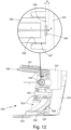
- each internal component 104 is preferably provided with one or more protruding fixing pins 107 made of opaque polymeric material, each of which extends parallel to a predefined insertion direction d 0 , and is adapted to arrange its distal end in abutment against the inner surface of rear casing 101, at a respective contact area 105.
- the laser welding joint 106 is moreover located at the distal end of the fixing pin 107.
- each fixing pin 107 is preferably also adapted to engage a corresponding receiving seat 108, which is realized directly on the rear casing 101, or rather on bottom of the rear casing 101, and is preferably substantially cup-shaped.
- the mutual contact area 105 is furthermore located inside said receiving seat 108.
- the distal end of fixing pin 107 is preferably adapted to stably rest on the bottom of receiving seat 108, and the contact area 105 is preferably located on the bottom of receiving seat 108.
- the receiving seat 108 preferably has a shape substantially complementary to that of the distal end of fixing pin 107.
- the fixing pins may protrude cantilevered from bottom of rear casing 101 and the receiving seats may be located on the internal component(s) 104 made of opaque polymeric material.
- the automotive lighting unit 100 may also comprise one or more cameras and/or one or more photosensitive sensors and/or one or more radar devices and/or one or more LiDAR (acronym of Light Detection and Ranging) instruments and/or other supplementary electronic devices, still housed inside the rigid housing formed/delimited by the rear casing 101 and by the front half-shell 102.
- LiDAR cronym of Light Detection and Ranging
- this or these supplementary electronic devices preferably include, or may include, one or more internal components at least partially made of opaque polymeric material, which are arranged with the part made of opaque polymeric material resting on the inner surface of rear casing 101 in at least one corresponding contact area 105, and are secured in a rigid non-removable manner to the rear casing 101 by means of at least one laser welding joint 106 made at said contact area 105.
- the automotive-lighting-units assembly machine 1 is adapted to form the laser welding joint(s) 106 which, at the contact area or areas 105, are adapted to secure the internal component or components 104 in a rigid non-removable manner directly to the rear casing 101, or rather directly on the inner surface of rear casing 101.
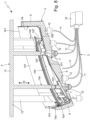
- the welding machine 1 firstly comprises: a workpiece carrying fixture 2, which is structured so as to temporarily accommodate and advantageously also retain the rear casing 101 with one or more internal components 104 inside; and a laser appliance 3 that, on command, is adapted to generate and direct at least one laser beam r towards/against the rear casing 101 accommodated in the workpiece carrying fixture 2.
- the workpiece carrying fixture 2 is structured so as to temporarily accommodate and advantageously also retain the rear casing 101 with inside one or more internal components 104 which rest on the inner surface of rear casing 101 at respective contact areas 105.
- the workpiece carrying fixture 2 is adapted to accommodate a rear casing 101 provided with at least one sector made of opaque polymeric material, and also with at least one internal component 104 which, in turn, is located inside the rear casing 101 and is provided with at least one portion made of opaque polymeric material that rests on the sector made of opaque polymeric material of rear casing 101 in at least one contact area 105.
- the laser appliance 3 is adapted to direct at least one laser beam r into the workpiece carrying fixture 2, in a direction such as to intersect a corresponding contact area 105 between the rear casing 101 and an internal component 104, so as to make at least one laser welding joint 106 at said contact area 105.
- the laser beam r furthermore has a wavelength ⁇ 0 higher than 400 nm (nanometres) and advantageously also higher than 900 nm (nanometres).
- the laser appliance 3 is adapted to direct the laser beam r towards the rear casing 101 stationary in the workpiece carrying fixture 2, so that said laser beam r passes through the sector made of opaque polymeric material of the rear casing 101 before intersecting said contact area 105.
- the laser appliance 3 is structured so as to focus/concentrate said laser beam r in a predefined point in space, in the following called focal point P, which is located inside the workpiece carrying fixture 2, behind (beyond) said contact area 105 between the rear casing 101 and the internal component 104, so as to form the laser welding joint 106 at the contact area 105.
- the distance w between the focal point P and the contact area 105 is furthermore lower than 3 mm (millimetres) and advantageously also higher than 0,2 mm (millimetres).
- the laser appliance 3 is provided with an optical focusing system, which is structured so as to focus/ concentrate said laser beam r in a focal point P that is located inside the workpiece carrying fixture 2, downstream of the contact area 105 towards which the laser beam r is directed.
- the focal point P is located on the opposite side of the contact area 105 with respect to the origin of the laser beam r, or rather with respect to the laser appliance 3, and is spaced from said contact area 105.
- the laser appliance 3, or rather its optical focusing system is preferably structured so as to shape the laser beam r substantially in the form of a cone, and the distance w between the focal point P, or rather the vertex of the cone, and the contact area 105 is preferably lower than 3 mm (millimetres) and advantageously also higher than 0,2 mm (millimetres).
- the laser appliance 3, or rather its optical focusing system is preferably structured so as to concentrate/focus said laser beam r in a focal point P, which is located inside the workpiece carrying fixture 2, downstream of said contact area 105 between the rear casing 101 and the internal component 104, at a distance w from the same contact area 105 preferably ranging between 0,2 and 2 mm (millimetres), and more advantageously between 0,5 to 1,5 mm (millimetres).
- the optical focusing system is preferably structured so that the laser beam r forms, downstream of said optical focusing system, a cone with an opening angle ⁇ advantageously ranging between 10° and 90°.
- the laser appliance 3 and the workpiece carrying fixture 2 are preferably structured so that the laser beam r directed towards the contact area 105 reaches/strikes the outer surface of the rear casing 101 advantageously passing through the workpiece carrying fixture 2.
- the laser appliance 3 is preferably coupled to the workpiece carrying fixture 2 so that the laser beam or beams r reach the rear casing 101 without passing through the mouth of the same rear casing 101.
- the automotive-lighting-units assembly machine 1 additionally comprises also a pressing assembly 4, which is selectively adapted to press against the inner surface of rear casing 101 accommodated in the workpiece carrying fixture 2 one or more internal components 104 previously placed inside the same rear casing 101.
- the pressing assembly 4 is preferably movable from and towards the workpiece carrying fixture 2 or vice versa, and is preferably structured so as to penetrate, when it is at a predefined minimum distance from the workpiece carrying fixture 2 (see Figures 7 and 8 ), inside the rear casing 101 accommodated in the workpiece carrying fixture 2 through the mouth of the same rear casing 101, for abutting on at least a part of the internal component or componets 104 present inside the rear casing 101, and then press the same internal components 104 against the inner surface of said rear casing 101, at the relative contact area or areas 105.
- the workpiece carrying fixture 2 preferably includes: a workpiece carrying template 5 with substantially non-deformable structure, which is preferably made of metallic material, and is provided with a receiving seat 5a adapted to accommodate the rear casing 101; and preferably also one or more, advantageously electrically- or pneumatically- operated, locking members (not visible in the figures) which are at least partially located on the workpiece carrying template 5 and are adapted to lock/immobilize, on command, the rear casing 101 in the receiving seat of the workpiece carrying template 5.
- the receiving seat 5a of the workpiece carrying template 5 preferably has a shape substantially complementary to that of the rear casing 101, and is provided with an access mouth through which the rear casing 101 is inserted and removed from the same receiving seat 5a.
- the workpiece carrying template 5 is preferably provided with one or more, advantageously in air, internal through passages 7, each of which extends through the body of the workpiece carrying template 5 up to the receiving seat 5a, and is structured so as to allow one or more laser beams r emitted by the laser appliance 3 to cross the same workpiece carrying template 5 substantially without energy losses or with minimum energy losses, until reaching the outer surface of the rear casing 101 momentarily accommodated in the workpiece carrying template 5.
- the/each through passage 7 preferably ends in the receiving seat 5a of the workpiece carrying template 5, so as to be directly faced to the rear casing 101 momentarily accommodated in the same receiving seat.
- the/each through passage 7 preferably ends inside the receiving seat 5a of the workpiece carrying template 5, so as to be locally aligned to a corresponding contact area 105 between the rear casing 101 and an internal component 104.
- the/each internal through passage 7 preferably consists of an opening, hole or rectilinear through duct, which is realized in the body of the workpiece carrying template 5, on a side opposite to the mouth of the receiving seat 5a.
- said opening, hole or rectilinear through duct is moreover locally aligned to a corresponding contact area 105 present inside the rear casing 101 momentarily accommodated in the receiving seat 5a of the workpiece carrying template 5.
- the laser appliance 3 preferably comprises: at least one electrically-powered laser source 10, which is able to emit, on command, a high-power laser beam, advantageously with a predefined and substantially constant intensity and/or emission spectrum; and one or more optic fibres 11, which ends substantially at the internal through passage or passages 7 of workpiece carrying fixture 2, and are optically coupled to the laser source 10 so as to channel the laser beam emitted by the laser source 10 to the respective through passage(s) 7.
- the laser appliance 3 furthermore comprises, for each optic fibre 11, also an optical focusing device 12 that is located downstream of the optic fibre 11 so as to be crossed by the laser beam r coming out of the same optic fibre 11, and is coupled to a respective through passage 7 of the workpiece carrying fixture 2 so as to direct the laser beam r coming out of the optic fibre 11 towards the contact area 105 locally aligned to the same through passage 7.
- the/each optical focusing device 12 is locally aligned to a respective through passage 7 of the workpiece carrying fixture 2, and is adapted to direct the laser beam r coming out of the relative optic fibre 11 inside the facing through passage 7 of the workpiece carrying fixture 2, towards the contact area 105 locally aligned to the same through passage 7.
- the optical focusing device 12 is structured so as to concentrate said laser beam r in a focal point P, which is located inside the receiving seat 5a of the workpiece carrying template 5, spaced behind the contact area 105 which the laser beam r is directed to.
- the optical focusing device 12 is preferably structured so as to concentrate/focus the laser beam r in a focal point P, which is located beyond the contact area 105 which the laser beam r is directed to, at a distance w from said contact area 105 of lower than 3 mm (millimetres) and advantageously also higher than 0,2 mm (millimetres).
- the optical focusing device 12 is structured so as to concentrate the laser beam r in a focal point P, which is located beyond the contact/support zone 105, at a distance w from the same contact area 105 preferably ranging between 0,2 and 2 mm (millimetres), or more advantageously ranging between 0,5 and 1,5 mm (millimetres).
- the optical focusing device 12 is preferably locally aligned to the corresponding contact area 105 between the rear casing 101 and an internal component 104, and preferably comprises one or more lenses advantageously of meniscus and/or planoconvex type, which are arranged one after the other so as to be crossed by the laser beam r coming out of the optic fibre 11.
- the optical focusing device 12 is preferably structured so as to concentrate the laser beam r in a focal point P, which is located downstream of the contact area 105, at a distance w from said contact area 105 preferably ranging between 0,5 and 1,2 mm (millimetres).
- the workpiece carrying fixture 2 is preferably provided with a plurality of through passages 7, each aligned to a respective contact area 105.
- the laser appliance 3 is preferably provided with a bundle of optic fibres 11 which end each at a respective through passage 7 of the workpiece carrying fixture 2, or rather of the workpiece carrying template 5; and a plurality of focusing devices 12 that are placed each downstream of a respective optic fibre 11 so as to be crossed by the laser beam r coming out of the same optic fibre 11.
- the bundle of optic fibres 11 is preferably optically coupled to the laser source 10 so as to split the high-power laser beam generated by the same laser source 10 into substantially equal parts between the various optic fibres 11 of the bundle.
- the bundle of optic fibres 11 may be coupled to the laser source 10 so as to distribute the high-power laser beam in a differentiated manner between the various optic fibres 11 of the bundle.
- a higher laser power may be channelled towards the optic fibre 11 that has its distal end very far from the corresponding contact area or zone 105 between the rear casing 101 and the internal component 104.
- the laser source 10 is preferably adapted to emit a laser beam with nominal power higher than 10 watt and/or a wavelength ⁇ 0 higher than 400 nm (nanometres) and advantageously also higher than 900 nm (nanometres).
- Each optical focusing device 12 is preferably aligned to a respective contact area 105 between the rear casing 101 and an internal component 104, and is preferably structured so as to at least partially engage a respective through passage 7 of the workpiece carrying fixture 2.
- each optical focusing device 12 is preferably also structured so as to retain the distal end of the relative optic fibre 11 firmly in place at the relative through passage 7.
- each optical focusing device 12 of laser appliance 3 is structured so as to concentrate the laser beam r coming out of the corresponding optic fibre 11 in a respective focal point Pi, which is located inside the receiving seat 5a of the workpiece carrying template 5, behind the contact area 105 which is locally aligned to the same focusing device 12.
- the distance w i separating the focal point P i from the corresponding contact area 105 moreover varies according to the morphology of the rear casing 101 and/or of the internal component 104 in the neighbourhood of the contact area 105, and/or according to the spatial position of the focal point Pi inside the receiving seat 5a of the workpiece carrying template 5.
- the optical focusing device 12 is provided with a fixing ferrule or terminal, which advantageously accommodates inside itself also the optics of the device, and is structured so as to lock the distal end of the optic fibre 11 in place at the relative opening, hole or rectilinear through duct of the workpiece carrying template 5.
- the pressing assembly 4 is preferably located in front of the workpiece carrying fixture 2, or rather the workpiece carrying template 5, and is preferably movable substantially rectilinearly from and towards the same workpiece carrying fixture 2 or vice versa.
- the pressing assembly 4 is preferably located in front of the mouth of the receiving seat 5a of the workpiece carrying template 5, and is movable substantially rectilinearly from and towards the same receiving seat.
- the pressing assembly 4 preferably includes a locking template 13 with substantially non-deformable structure, which is advantageously made of metallic material, and is provided with one or more oblong protruding appendages, each of which is shaped so as to freely penetrate into the rear casing 101 momentarily accommodated in the workpiece carrying fixture 2 through the mouth of the same rear casing 101, and press a corresponding internal component 104 firmly in abutment against the inner surface of the rear casing 101, clearly at a relative contact area 105.
- a locking template 13 with substantially non-deformable structure which is advantageously made of metallic material, and is provided with one or more oblong protruding appendages, each of which is shaped so as to freely penetrate into the rear casing 101 momentarily accommodated in the workpiece carrying fixture 2 through the mouth of the same rear casing 101, and press a corresponding internal component 104 firmly in abutment against the inner surface of the rear casing 101, clearly at a relative contact area 105.
- the locking template 13 is preferably provided with one or more shaped protrusions 13a, which extend cantilevered parallel to the movement direction d of the pressing assembly 4 from and towards the workpiece carrying fixture 2 or vice versa.
- the shaped protrusion or protrusions 13a of locking template 13 are preferably aligned each to a respective contact area 105, and are preferably structured so as to abut against the corresponding internal component or components 104 present inside the rear casing 101, each at the back of a respective fixing pin 107 of the internal component 104.
- the workpiece carrying fixture 2 and the pressing assembly 4 are preferably arranged one spaced above the other, vertically aligned to one another, and are preferably movable one from and towards the other in a substantially rectilinear manner.
- the workpiece carrying template 5 is preferably oriented with the mouth of the receiving seat 5a turned upwards, so that the internal component(s) 104 remain in place by gravity inside the rear casing 101 temporarily accommodated in the same workpiece carrying template 5.
- the pressing assembly 4, or rather the locking template 13 is preferably arranged spaced above the workpiece carrying fixture 2, or rather above the workpiece carrying template 5, with the shaped protrusion(s) 13a turned downwards, i.e. towards the workpiece carrying template 5.
- the pressing assembly 4, or rather the locking template 13 is furthermore stationary in space, while the workpiece carrying fixture 2, or rather the workpiece carrying template 5, and advantageously also at least part of the laser appliance 3 is/are movable vertically from and towards the pressing assembly 4, or rather the locking template 13.
- the pressing assembly 4, or rather the locking template 13 may move rectilinearly from and towards the workpiece carrying fixture 2 that instead remains stationary in space.
- the automotive-lighting-units assembly machine 1 is preferably provided with a rigid supporting framework 20, which is structured to be stably rested on, and optionally be also rigidly anchored to, the ground.
- the workpiece carrying fixture 2 and the pressing assembly 4 are preferably located on the supporting framework 20 one above the other, vertically aligned to one another.
- the pressing assembly 4 is preferably fixed to the top of supporting framework 20, with the locking template 13, or rather the shaped protrusion(s) 13a of the locking template 13, turned downwards.
- the workpiece carrying fixture 2 is preferably fixed to the supporting framework 20 spaced beneath the pressing assembly 4, with the mouth of the receiving seat 5a of the workpiece carrying template 5 turned upwards, and with the capability of moving vertically from and towards the pressing assembly 4.
- the laser appliance 3 is preferably located on the supporting framework 20 beneath the workpiece carrying fixture 2, or rather beneath the workpiece carrying template 5.
- the automotive-lighting-units assembly machine 1 preferably also comprises: an advantageously pneumatically- or hydraulically- operated, a moving device 21 which is adapted to vertically move the workpiece carrying fixture 2 from and towards the pressing assembly 4; and an electronic control device 22 which is adapted to command the moving device 21.
- the moving device 21 is adapted to move, on command, the workpiece carrying fixture 2 between a raised position (see Figures 7 and 8 ) in which the workpiece carrying template 5 is at a given minimum distance from the locking template 13 of the pressing assembly 4, and a lowered position (see Figures 1 and 6 ) in which the workpiece carrying template 5 is at a given maximum distance from the locking template 13 of the pressing assembly 4.
- the shaped protrusion or protrusions 13a of the locking template 13 penetrate inside the rear casing 101 accommodated in the workpiece carrying fixture 2, so as to reach and press at least part of the internal component or components 104 present inside the rear casing 101 against the inner surface of said rear casing 101, at the relative contact area(s) or zone(s) 105.
- the shaped protrusion or protrusions 13a of the locking template 13 are instead far from the workpiece carrying template 5 so as not to hinder, or rather to facilitate, removal and insertion of the rear casing 101 from/into the receiving seat 5a of the workpiece carrying template 5.
- the supporting framework 20 preferably has a gantry structure, and is therefore provided with at least one pair of vertical uprights and an upper crossbeam that extends more or less horizontally and bridge-like between the upper ends of the vertical uprights.
- the pressing assembly 4 is preferably rigidly fixed to the upper crossbeam of the supporting framework 20.
- the workpiece carrying fixture 2, on the other hand, is preferably fixed above a movable platform, which is located spaced beneath the upper crossbeam and is advantageously coupled in a vertically slidable manner to the vertical uprights of the supporting framework 20.
- the moving device 21 preferably comprises a pair of double-acting hydraulic cylinders or the like, which are arranged in a vertical position each beside a respective vertical upright of supporting framework 20, and are adapted to raise and lower, on command, the movable platform that accommodates the workpiece carrying fixture 2.
- the moving system of machine 1 may move vertically the pressing assembly 4 from and towards the workpiece carrying fixture 2, or may move vertically both the workpiece carrying fixture 2 and the pressing assembly 4.
- the assembly of automotive lighting unit 100 comprises the step of placing said at least one internal component 104 inside the rear casing 101, with the part/portion made of opaque polymeric material resting on the sector made of opaque polymeric material of the rear casing 101 in at least one contact area 105; and then the step of securing said at least one internal component 104 in a rigid and substantially non-removable manner to the rear casing 101, making at least one laser welding joint 106 at said mutual contact area 105.
- the step of rigidly securing the internal component 104 to the rear casing 101 entails directing, for a predefined time interval advantageously lower than 30 s (seconds), a laser beam r towards said at least one contact area 105, shaping the same laser beam r so as to concentrate/focus said laser beam r in a predefined point in space, in the following called focal point P, which is located downstream of the same contact area 105, at a given distance w from said contact area 105, in order to temporarily heating to melting point the only polymeric material present in the neighbourhood of the same contact area 105.
- the laser beam r is shaped substantially in the form of a cone.
- the distance w is preferably lower than 3 mm (millimetres) and/or greater than 0,2 mm (millimetres), and is selected so that the laser beam r causes, at the contact area 105 which it is directed to, a localized temperature peak/increase, the value of which is such as to cause the melting of the opaque polymeric materials that locally form, respectively, the internal component 104 and the rear casing 101.
- the laser beam r is moreover locally substantially perpendicular to said contact area 105 and/or has a wavelength ⁇ 0 advantageously higher than 900 nm (nanometres).
- the assembly of automotive lighting unit 100 entails shaping the laser beam r so as to concentrate/ focus the same laser beam r in a focal point P, which is located beyond the contact area 105 between the internal component 104 and the rear casing 101, at a distance w from said contact area 105 preferably ranging between 0,2 and 2 mm (millimetres), and more advantageously ranging between 0,5 and 1,5 mm (millimetres).
- the assembly of automotive lighting unit 100 preferably entails orienting the laser beam r so that, before reaching the contact area 105, it firstly passes through the piece locally made of the opaque polymeric material having lower absorption coefficient ⁇ .
- the absorption coefficient ⁇ of the piece firstly crossed by the laser beam r is preferably lower by at least 25%, and more advantageously at least 40%, than the absorption coefficient ⁇ of the piece crossed secondly by the laser beam r.
- the difference between the absorption coefficients ⁇ of the two opaque polymeric materials is preferably greater than 35% of the absorption coefficient ⁇ with higher value.
- the laser beam r is preferably oriented so as to first pass through the sector made of opaque polymeric material of the rear casing 101, and the opaque polymeric material that forms said opaque-polymeric - material sector therefore has a laser-beam absorption coefficient ⁇ lower than that of the opaque polymeric material forming the adjacent portion of internal component 104.
- the assembly of automotive lighting unit 100 preferably entails concentrating/focusing the laser beam r in a focal point P, which is located behind the contact area 105 between the internal component 104 and the rear casing 101, at a distance w from the same contact area 105 advantageously ranging between 0,5 and 1,2 mm (millimetres).
- the making of the laser welding joint 106 at the contact area 105 between the internal component 104 and the rear casing 101 takes place for the following reasons, without compromising the structural integrity of the rear casing 101 and the internal component 104.
- the quantity of energy transferred by the laser beam r to the polymeric material per unit of length of the optical path increases with the growing of the laser-beam absorption coefficient ⁇ associated to the polymeric material which is crossed by the laser beam r.
- the use of a very powerful laser beam is not feasible in reality, because the laser beam would transfer a huge amount of energy to the opaque polymeric material it runs in before reaching the contact area 105 that, in Figure 9 , is located at the distance w 0 from the incidence point, irreparably damaging the material. Obviously, the distance w 0 corresponds to the local thickness of the rear casing 101.
- the laser beam r substantially in the form of a cone before it penetrates into the rear casing 101, directed towards the contact area 105 between the rear casing 101 and the internal component 104, it is possible to maintain, up to the contact area 105, the energy density at relatively low values that can be withstood by the opaque polymeric material.
- the focused laser beam r affects a gradually smaller area progressively increasing the energy density.
- the energy density reaches a value such as to locally melt the polymeric material.
- the focused laser beam r melts the polymeric material located at the contact area 105 without, however, melting or otherwise damaging the polymeric material upstream of the contact area 105.
- the temperature trend of the polymeric material along the path followed by the laser beam further improves if the absorption coefficient ⁇ 101 of the polymeric material that forms the rear casing 101 is lower than the absorption coefficient ⁇ 104 of the polymeric material that forms the internal component 104.
- the temperature trend of the polymeric material along the path followed by the laser beam changes radically.
- Figure 11 shows the temperature trend of the polymeric material along the path followed by the shaped laser beam r, when the laser beam r is concentrated/focused in a focal point P that is located beyond/downstream of the contact area 105, at a distance w of nearly 0,6 mm from said contact area 105, and the absorption coefficient ⁇ 101 of the polymeric material that forms the rear casing 101, i.e. the absorption coefficient ⁇ of the material first crossed by the laser beam r, is equal to approximately half that of the polymeric material that forms the internal component 104, i.e. the absorption coefficient ⁇ 104 .
- the absorption coefficient ⁇ of the piece first and entirely crossed by the laser beam r i.e. the absorption coefficient ⁇ 101 of the rear casing 101
- the absorption coefficient ⁇ 101 of the rear casing 101 must be preferably at least 25%, and more advantageously at least 40%, lower than the absorption coefficient ⁇ of the piece reached second by the laser beam r, i.e. the absorption coefficient ⁇ 104 of the internal component 104.
- the difference between the absorption coefficients ⁇ of the two opaque polymeric materials must advantageously be higher than 35% of the absorption coefficient ⁇ with higher value.
- the absorption coefficient ⁇ 101 of the polymeric material that forms the rear casing 101 must be preferably between 0,05 (1/mm) and 1 (1/mm), and more advantageously between 0,1 (1/mm) and 0,2 (1/mm).
- the absorption coefficient ⁇ 104 of the polymeric material that forms the internal component 104 must be preferably between 0,2 (1/mm) and 3 (1/mm), and more advantageously between 0,8 (1/mm) and 2 (1/mm).
- the step of rigidly securing the internal component 104 to the rear casing 101 additionally entails pressing the internal component 104 to be welded against the inner surface of the rear casing 101, at the/each contact area 105, while the laser beam r heats the opaque polymeric materials in the neighbourhood of the contact area 105.
- the assembly of automotive lighting unit 100 preferably comprises, after the making of the various laser welding joints 106, also the step of welding the front half-shell 102 on the mouth of the rear casing 101.
- the assembly of automotive lighting unit 100 preferably ends with the welding of the front half-shell 102 on the mouth of the rear casing 101.
- the assembly of automotive lighting unit 100 preferably comprises the step of placing the rear casing 101 in the workpiece carrying fixture 2, or rather inside the receiving seat 5a of the workpiece carrying template 5; and advantageously also the step of locking/immobilizing the same rear casing 101 in the workpiece carrying fixture 2, or rather inside the receiving seat of the workpiece carrying template 5.
- the assembly of automotive lighting unit 100 preferably comprises the step of placing the internal component or components 104 inside the rear casing 101 stationary in the workpiece carrying fixture 2, each resting on the inner surface of the rear casing 101 in at least one respective contact area 105.
- the assembly of automotive lighting unit 100 comprises the step of activating the laser appliance 3 so as to direct the laser beam(s) r towards the contact area(s) 105 between the rear casing 101 and the internal component(s) 104, shaping each laser beam r substantially in the form of a cone so as to concentrate/focus the same laser beam r in a focal point P, which is located downstream of the corresponding contact area 105, at a distance w from said contact area 105 preferably ranging between 0,2 and 2 mm (millimetres), or more advantageously between 0,5 and 1,5 mm (millimetres).
- the assembly of automotive lighting unit 100 furthermore entails directing the laser beam or beams r towards the contact area or areas 105 between the rear casing 101 and the internal component or components 104, causing said laser beam or beams r to pass inside the through passages 7 present in the workpiece carrying fixture 2.
- the laser beam r When reaches the relative contact area 105, the laser beam r locally heats up the rear casing 101 and the internal component 104, bringing the polymeric materials to melting temperature.
- the subsequent re-hardening of the polymeric material joins the two pieces in a rigid and non-removable manner, forming the laser welding joint 106.
- the assembly of automotive lighting unit 100 preferably also comprises the step of activating the pressing assembly 4 so as to press, against the inner surface of the rear casing 101 momentarily accommodated in the workpiece carrying fixture 2, the internal component or components 104 previously placed inside the same rear casing 101.
- the assembly of automotive lighting unit 100 preferably entails moving the locking template 13 of the pressing assembly 4 towards the workpiece carrying template 5 of the workpiece carrying fixture 2, so as to introduce the shaped protrusion(s) 13a of the locking template 13 inside the rear casing 101 present in the workpiece carrying fixture 2, up to reach and press the internal component(s) 104 against the inner surface of the same rear casing 101, at the respective contact areas 105.
- the securing of the internal components 104 of the automotive lighting unit 100 to the rear casing 101 by means of the laser welding joints 106 allows to eliminate all, or in any case the majority of, the metal screws currently used to secure the internal components of the automotive lighting unit to its rear casing, with the remarkable reduction of weight and production costs that this entails.
- the immediate securing of the internal component or components 104 by means of the laser welding joints 106 allows to eliminate, or at least drastically reduce, the number of shoulders, centring pins and/or snap-on locking tabs usually present inside the rear casing of an automotive lighting unit, thus considerably simplifying the structure of the mould used to produce the rear casing 101.
- centring and/or snap locking systems results in an extremely complicated shape of the mould used to produce the rear casing of an automotive lighting unit assembled in a traditional manner.
- the welding with the aid of laser beams r that are shaped so as to be concentrated/focused in focal points P located behind the corresponding contact areas 105, at a predefined distance w from the same contact areas 105 solves all the operating limits connected to the use of internal lighting pieces/components made of polymeric material opaque to visible light.
- the opaque polymeric material that constitutes the piece located upstream of the contact area 105, along the path of the laser beam r that makes the laser welding joint 106 has an absorption coefficient ⁇ lower than that of the opaque polymeric material constituting the piece located downstream of the contact area 105, it is possible to drastically reduce the thermal stress on the first piece made of opaque polymeric material.
- the automotive-lighting-units assembly machine 1 greatly simplifies the automotive-lighting-unit assembly line, with all the advantages that this entails. In fact, the automatic screwdriver(s) are no longer necessary.
- the step of rigidly securing the internal component 104 to the rear casing 101 entails shaping the laser beam r so as to concentrate/ focus said laser beam r in a focal point P located at the contact area 105.
- the optical focusing system of the laser appliance 3 is therefore structured so as to concentrate/focus the laser beam r in a focal point P that is located substantially at the contact area 105 between the rear casing 101 and the internal component 104.
- the laser beam r is preferably oriented so as to intersect first the internal component 104, or rather the distal end of the fixing pin 107, and then the rear casing 101.
- the absorption coefficient ⁇ 101 of the polymeric material that forms the rear casing 101 is higher than the absorption coefficient ⁇ 104 of the polymeric material that forms the internal component 104.
- the laser beam r is preferably anyway concentrated/ focused in a focal point P which is located beyond the contact area 105 between the rear casing 101 and the internal component 104, at a distance w from the same contact area 105 preferably lower than 3 mm (millimetres), or rather ranging between 0,2 and 2 mm (millimetres) and more advantageously between 0,5 and 1,5 mm (millimetres).
- the focal point P where the laser beam r is concentrated is located inside the thickness of the rear casing 101.
- the laser appliance 3 may comprise a series of independent laser sources, each of which is structured so as to emit, on command, a laser beam r towards a corresponding contact area 105 between the rear casing 101 and an internal component 104, concentrating/focusing the same laser beam r in a focal point P, which is located beyond said contact area 105, at a distance w from the same contact area 105 preferably lower than 3 mm (millimetres), or rather ranging between 0,2 and 2 mm (millimetres) and more advantageously between 0,5 and 1,5 mm (millimetres) .
- activation and deactivation of the independent laser sources may not take place simultaneously for all the laser sources.
- the laser appliance 3 may comprise, in place of the bundle of optic fibres 11, a movable laser deflector, which is able to divert, on command, the laser beam produced by the laser source 10, on choice and alternatively, towards each focusing device 12 which, in turn, is aligned to a respective contact area 105 between the rear casing 101 and an internal component 104.
- the laser welding joints 106 would be made one after the other, preferably according to a predefined time sequence.
- the laser appliance 3 may comprise, in place of the bundle of optic fibres 11, a movable robotic arm, which supports a laser source and is capable to align, on command, the laser source to any one contact area 105 between the rear casing 101 and an inner component 104, or to the optical focusing device 12 locally aligned to the same contact area 105, so as to direct the laser beam r towards the contact area 105, concentrating/focusing said laser beam r in a focal point P preferably located beyond said contact area 105.
- the rear casing 101 may have one or more sectors made of transparent polymeric material, adjoined or surrounded by one or more sectors made of opaque polymeric material preferably having larger dimensions.
- the contact area 105 between the rear casing 101 and the/each internal component 104 is located at the or at one of the sectors made of opaque polymeric material that form the rear casing 101.
Landscapes
- Engineering & Computer Science (AREA)
- Mechanical Engineering (AREA)
- Physics & Mathematics (AREA)
- Optics & Photonics (AREA)
- Health & Medical Sciences (AREA)
- Toxicology (AREA)
- Electromagnetism (AREA)
- Lining Or Joining Of Plastics Or The Like (AREA)
Priority Applications (3)
| Application Number | Priority Date | Filing Date | Title |
|---|---|---|---|
| EP23199334.6A EP4527596A1 (fr) | 2023-09-25 | 2023-09-25 | Procédé d'assemblage d'une unité d'éclairage automobile et machine mettant en oeuvre ledit procédé |
| US18/894,323 US20250102129A1 (en) | 2023-09-25 | 2024-09-24 | Assembly Method of an Automotive Lighting Unit and Machine Implementing Such Method |
| CN202411342133.7A CN119682223A (zh) | 2023-09-25 | 2024-09-25 | 汽车照明单元的组装方法和实施这种方法的机器 |
Applications Claiming Priority (1)
| Application Number | Priority Date | Filing Date | Title |
|---|---|---|---|
| EP23199334.6A EP4527596A1 (fr) | 2023-09-25 | 2023-09-25 | Procédé d'assemblage d'une unité d'éclairage automobile et machine mettant en oeuvre ledit procédé |
Publications (1)
| Publication Number | Publication Date |
|---|---|
| EP4527596A1 true EP4527596A1 (fr) | 2025-03-26 |
Family
ID=88920952
Family Applications (1)
| Application Number | Title | Priority Date | Filing Date |
|---|---|---|---|
| EP23199334.6A Pending EP4527596A1 (fr) | 2023-09-25 | 2023-09-25 | Procédé d'assemblage d'une unité d'éclairage automobile et machine mettant en oeuvre ledit procédé |
Country Status (1)
| Country | Link |
|---|---|
| EP (1) | EP4527596A1 (fr) |
Citations (3)
| Publication number | Priority date | Publication date | Assignee | Title |
|---|---|---|---|---|
| US20040070988A1 (en) * | 2002-10-14 | 2004-04-15 | Guide Corporation | Hermetically sealed lamp housing and method of making |
| EP3388222A1 (fr) * | 2017-04-14 | 2018-10-17 | Automotive Lighting Italia S.p.A. | Appareil de soudage laser simultané et procédé de soudage laser simultané d'un phare de véhicule |
| EP3608086A1 (fr) * | 2018-08-10 | 2020-02-12 | Automotive Lighting Italia S.p.A. | Machine permettant de souder des pièces constituées de matériaux plastiques |
-
2023
- 2023-09-25 EP EP23199334.6A patent/EP4527596A1/fr active Pending
Patent Citations (3)
| Publication number | Priority date | Publication date | Assignee | Title |
|---|---|---|---|---|
| US20040070988A1 (en) * | 2002-10-14 | 2004-04-15 | Guide Corporation | Hermetically sealed lamp housing and method of making |
| EP3388222A1 (fr) * | 2017-04-14 | 2018-10-17 | Automotive Lighting Italia S.p.A. | Appareil de soudage laser simultané et procédé de soudage laser simultané d'un phare de véhicule |
| EP3608086A1 (fr) * | 2018-08-10 | 2020-02-12 | Automotive Lighting Italia S.p.A. | Machine permettant de souder des pièces constituées de matériaux plastiques |
Similar Documents
| Publication | Publication Date | Title |
|---|---|---|
| US10507764B2 (en) | Vehicle interior trim assembly configured to form a light pattern having an emblem shape at the front of a trim part such as an air bag cover | |
| US7815354B2 (en) | Vehicle lamp housing with transparent cover welded thereon, and method | |
| CN107443758B (zh) | 树脂成型品和焊接装置 | |
| US9482403B2 (en) | Automotive light and method of manufacturing | |
| FR2644120A1 (fr) | Dispositif d'eclairage vers l'avant pour vehicule | |
| JP2000294013A (ja) | 車両用灯具 | |
| JPH11348132A (ja) | レ−ザ溶着方法及びレ−ザ溶接装置 | |
| US11649939B2 (en) | Automotive lighting and/or signaling device and assembly method thereof | |
| EP2725290B1 (fr) | Phare de véhicule et son procédé de production | |
| JP2006012502A (ja) | 車輌用灯具の製造方法及び車輌用灯具の製造装置。 | |
| US7287877B2 (en) | Vehicular lighting device and beam welding method | |
| EP4527596A1 (fr) | Procédé d'assemblage d'une unité d'éclairage automobile et machine mettant en oeuvre ledit procédé | |
| EP4527594A1 (fr) | Procédé d'assemblage d'une unité d'éclairage automobile et machine mettant en oeuvre ledit procédé | |
| US20250102129A1 (en) | Assembly Method of an Automotive Lighting Unit and Machine Implementing Such Method | |
| EP4527595A1 (fr) | Procédé d'assemblage d'une unité d'éclairage automobile et machine mettant en oeuvre un tel procédé | |
| CN109664020B (zh) | 车灯的同步激光焊接设备和车灯的同步激光焊接方法 | |
| EP4528150A1 (fr) | Dispositif d'éclairage automobile et procédé de production associé | |
| EP4527593A1 (fr) | Unité d'éclairage automobile et procédé de production associé | |
| JP2000294012A (ja) | 車両用標識灯 | |
| US11060683B2 (en) | Lighting device for a motor vehicle, and method for producing same | |
| CN114008380B (zh) | 车辆用前照灯 | |
| KR102578874B1 (ko) | 라이센스 램프 제조 시스템 및 이에 의해 수행되는 제조 방법 | |
| KR102261162B1 (ko) | 레이저빔 반사채널 및 스캐너를 이용한 레이저플라스틱 용접장치 | |
| JP2015185375A (ja) | 車両用灯具 | |
| CN120620662A (zh) | 灯罩的加工方法、灯具及载具 |
Legal Events
| Date | Code | Title | Description |
|---|---|---|---|
| PUAI | Public reference made under article 153(3) epc to a published international application that has entered the european phase |
Free format text: ORIGINAL CODE: 0009012 |
|
| STAA | Information on the status of an ep patent application or granted ep patent |
Free format text: STATUS: THE APPLICATION HAS BEEN PUBLISHED |
|
| AK | Designated contracting states |
Kind code of ref document: A1 Designated state(s): AL AT BE BG CH CY CZ DE DK EE ES FI FR GB GR HR HU IE IS IT LI LT LU LV MC ME MK MT NL NO PL PT RO RS SE SI SK SM TR |
|
| STAA | Information on the status of an ep patent application or granted ep patent |
Free format text: STATUS: REQUEST FOR EXAMINATION WAS MADE |
|
| 17P | Request for examination filed |
Effective date: 20250924 |