EP4527607A1 - Équipement pour la fabrication de barquettes à rebords de différentes dimensions ou de différents types - Google Patents
Équipement pour la fabrication de barquettes à rebords de différentes dimensions ou de différents types Download PDFInfo
- Publication number
- EP4527607A1 EP4527607A1 EP24201718.4A EP24201718A EP4527607A1 EP 4527607 A1 EP4527607 A1 EP 4527607A1 EP 24201718 A EP24201718 A EP 24201718A EP 4527607 A1 EP4527607 A1 EP 4527607A1
- Authority
- EP
- European Patent Office
- Prior art keywords
- equipment
- forming
- tray
- dimensions
- punched
- Prior art date
- Legal status (The legal status is an assumption and is not a legal conclusion. Google has not performed a legal analysis and makes no representation as to the accuracy of the status listed.)
- Pending
Links
Images


Classifications
-
- B—PERFORMING OPERATIONS; TRANSPORTING
- B31—MAKING ARTICLES OF PAPER, CARDBOARD OR MATERIAL WORKED IN A MANNER ANALOGOUS TO PAPER; WORKING PAPER, CARDBOARD OR MATERIAL WORKED IN A MANNER ANALOGOUS TO PAPER
- B31B—MAKING CONTAINERS OF PAPER, CARDBOARD OR MATERIAL WORKED IN A MANNER ANALOGOUS TO PAPER
- B31B50/00—Making rigid or semi-rigid containers, e.g. boxes or cartons
- B31B50/02—Feeding or positioning sheets, blanks or webs
- B31B50/04—Feeding sheets or blanks
- B31B50/06—Feeding sheets or blanks from stacks
- B31B50/066—Feeding sheets or blanks from stacks from above a magazine
-
- B—PERFORMING OPERATIONS; TRANSPORTING
- B31—MAKING ARTICLES OF PAPER, CARDBOARD OR MATERIAL WORKED IN A MANNER ANALOGOUS TO PAPER; WORKING PAPER, CARDBOARD OR MATERIAL WORKED IN A MANNER ANALOGOUS TO PAPER
- B31B—MAKING CONTAINERS OF PAPER, CARDBOARD OR MATERIAL WORKED IN A MANNER ANALOGOUS TO PAPER
- B31B50/00—Making rigid or semi-rigid containers, e.g. boxes or cartons
- B31B50/006—Controlling; Regulating; Measuring; Improving safety
-
- B—PERFORMING OPERATIONS; TRANSPORTING
- B31—MAKING ARTICLES OF PAPER, CARDBOARD OR MATERIAL WORKED IN A MANNER ANALOGOUS TO PAPER; WORKING PAPER, CARDBOARD OR MATERIAL WORKED IN A MANNER ANALOGOUS TO PAPER
- B31B—MAKING CONTAINERS OF PAPER, CARDBOARD OR MATERIAL WORKED IN A MANNER ANALOGOUS TO PAPER
- B31B50/00—Making rigid or semi-rigid containers, e.g. boxes or cartons
- B31B50/02—Feeding or positioning sheets, blanks or webs
- B31B50/04—Feeding sheets or blanks
- B31B50/044—Feeding sheets or blanks involving aligning
-
- B—PERFORMING OPERATIONS; TRANSPORTING
- B31—MAKING ARTICLES OF PAPER, CARDBOARD OR MATERIAL WORKED IN A MANNER ANALOGOUS TO PAPER; WORKING PAPER, CARDBOARD OR MATERIAL WORKED IN A MANNER ANALOGOUS TO PAPER
- B31B—MAKING CONTAINERS OF PAPER, CARDBOARD OR MATERIAL WORKED IN A MANNER ANALOGOUS TO PAPER
- B31B50/00—Making rigid or semi-rigid containers, e.g. boxes or cartons
- B31B50/02—Feeding or positioning sheets, blanks or webs
- B31B50/04—Feeding sheets or blanks
- B31B50/07—Feeding sheets or blanks by air pressure or suction
-
- B—PERFORMING OPERATIONS; TRANSPORTING
- B31—MAKING ARTICLES OF PAPER, CARDBOARD OR MATERIAL WORKED IN A MANNER ANALOGOUS TO PAPER; WORKING PAPER, CARDBOARD OR MATERIAL WORKED IN A MANNER ANALOGOUS TO PAPER
- B31B—MAKING CONTAINERS OF PAPER, CARDBOARD OR MATERIAL WORKED IN A MANNER ANALOGOUS TO PAPER
- B31B50/00—Making rigid or semi-rigid containers, e.g. boxes or cartons
- B31B50/26—Folding sheets, blanks or webs
- B31B50/44—Folding sheets, blanks or webs by plungers moving through folding dies
- B31B50/46—Folding sheets, blanks or webs by plungers moving through folding dies and interconnecting side walls
-
- B—PERFORMING OPERATIONS; TRANSPORTING
- B31—MAKING ARTICLES OF PAPER, CARDBOARD OR MATERIAL WORKED IN A MANNER ANALOGOUS TO PAPER; WORKING PAPER, CARDBOARD OR MATERIAL WORKED IN A MANNER ANALOGOUS TO PAPER
- B31B—MAKING CONTAINERS OF PAPER, CARDBOARD OR MATERIAL WORKED IN A MANNER ANALOGOUS TO PAPER
- B31B2100/00—Rigid or semi-rigid containers made by folding single-piece sheets, blanks or webs
- B31B2100/002—Rigid or semi-rigid containers made by folding single-piece sheets, blanks or webs characterised by the shape of the blank from which they are formed
- B31B2100/0024—Rigid or semi-rigid containers made by folding single-piece sheets, blanks or webs characterised by the shape of the blank from which they are formed having all side walls attached to the bottom
-
- B—PERFORMING OPERATIONS; TRANSPORTING
- B31—MAKING ARTICLES OF PAPER, CARDBOARD OR MATERIAL WORKED IN A MANNER ANALOGOUS TO PAPER; WORKING PAPER, CARDBOARD OR MATERIAL WORKED IN A MANNER ANALOGOUS TO PAPER
- B31B—MAKING CONTAINERS OF PAPER, CARDBOARD OR MATERIAL WORKED IN A MANNER ANALOGOUS TO PAPER
- B31B2110/00—Shape of rigid or semi-rigid containers
- B31B2110/30—Shape of rigid or semi-rigid containers having a polygonal cross section
- B31B2110/35—Shape of rigid or semi-rigid containers having a polygonal cross section rectangular, e.g. square
-
- B—PERFORMING OPERATIONS; TRANSPORTING
- B31—MAKING ARTICLES OF PAPER, CARDBOARD OR MATERIAL WORKED IN A MANNER ANALOGOUS TO PAPER; WORKING PAPER, CARDBOARD OR MATERIAL WORKED IN A MANNER ANALOGOUS TO PAPER
- B31B—MAKING CONTAINERS OF PAPER, CARDBOARD OR MATERIAL WORKED IN A MANNER ANALOGOUS TO PAPER
- B31B50/00—Making rigid or semi-rigid containers, e.g. boxes or cartons
- B31B50/60—Uniting opposed surfaces or edges; Taping
- B31B50/62—Uniting opposed surfaces or edges; Taping by adhesives
- B31B50/624—Applying glue on blanks
-
- B—PERFORMING OPERATIONS; TRANSPORTING
- B31—MAKING ARTICLES OF PAPER, CARDBOARD OR MATERIAL WORKED IN A MANNER ANALOGOUS TO PAPER; WORKING PAPER, CARDBOARD OR MATERIAL WORKED IN A MANNER ANALOGOUS TO PAPER
- B31B—MAKING CONTAINERS OF PAPER, CARDBOARD OR MATERIAL WORKED IN A MANNER ANALOGOUS TO PAPER
- B31B50/00—Making rigid or semi-rigid containers, e.g. boxes or cartons
- B31B50/60—Uniting opposed surfaces or edges; Taping
- B31B50/68—Uniting opposed surfaces or edges; Taping by stitching, stapling or riveting
-
- B—PERFORMING OPERATIONS; TRANSPORTING
- B65—CONVEYING; PACKING; STORING; HANDLING THIN OR FILAMENTARY MATERIAL
- B65B—MACHINES, APPARATUS OR DEVICES FOR, OR METHODS OF, PACKAGING ARTICLES OR MATERIALS; UNPACKING
- B65B43/00—Forming, feeding, opening or setting-up containers or receptacles in association with packaging
- B65B43/26—Opening or distending bags; Opening, erecting, or setting-up boxes, cartons, or carton blanks
-
- B—PERFORMING OPERATIONS; TRANSPORTING
- B65—CONVEYING; PACKING; STORING; HANDLING THIN OR FILAMENTARY MATERIAL
- B65B—MACHINES, APPARATUS OR DEVICES FOR, OR METHODS OF, PACKAGING ARTICLES OR MATERIALS; UNPACKING
- B65B43/00—Forming, feeding, opening or setting-up containers or receptacles in association with packaging
- B65B43/42—Feeding or positioning bags, boxes, or cartons in the distended, opened, or set-up state; Feeding preformed rigid containers, e.g. tins, capsules, glass tubes, glasses, to the packaging position; Locating containers or receptacles at the filling position; Supporting containers or receptacles during the filling operation
- B65B43/44—Feeding or positioning bags, boxes, or cartons in the distended, opened, or set-up state; Feeding preformed rigid containers, e.g. tins, capsules, glass tubes, glasses, to the packaging position; Locating containers or receptacles at the filling position; Supporting containers or receptacles during the filling operation from supply magazines
Definitions
- the present invention relates to an equipment for making edged trays starting from punched sheets, preferably in cardboard.
- Said edged trays are adapted, for example, to hold bottles or other containers.
- Said equipment for making edged trays comprise a magazine for the punched sheets, arranged in a stack, a handling element for at least one sheet to be processed, and a plurality of forming walls into which the sheet is forcibly inserted, so as to obtain, by virtue of the folding of flaps and fins of the same sheet, the above-mentioned edged tray.
- Said punched sheets are generally stacked in a magazine, preferably in a vertical or horizontal extension.
- the forming equipment generally provide for an adequate handling element, which transfers the punched sheet to the forming zone, where the punched sheet is arranged at a die comprising a plurality of forming walls, so shaped as to create in the punched sheet the folds, defined by the pre-existing creasing lines, required for making the edged tray.
- a special punch forces the punched sheet into the space defined by the forming walls, causing the folding of the flaps and fins defined by the above-mentioned creasing lines. and at least partially making the tray.
- This operation can be referred to as deep drawing.
- edged tray generally is completed with the aid of any auxiliary forming means, which provide, for example, the closure of the same tray with glue or staples or by interlocking, or in any case, ensure its finishing in accordance with the provisions defined during the design phase.
- a second handling element picks up the tray format and brings it at a storage station, from where such tray can be retrieved for future use.
- the known equipment comprise a single magazine of stacked punched sheets, in a vertical extension, arranged for example laterally to the forming zone of the punched sheets.
- said equipment can be fed with a single type of punched sheet at a time.
- the forming zone is so shaped as to be able to process a single type of punched sheet at a time; therefore, also the forming walls of the die are possibly adjustable, partially manually.
- said known equipment is not flexible enough to simultaneously produce trays of different shape and dimension, which involves a labour-intensive format change with long execution times, making said machines not very flexible.
- the technical problem underlying the present invention is to provide an equipment for making edged trays starting from punched sheets, structurally and functionally designed to overcome one or more of the limitations set forth above with reference to the cited prior art.
- a main object of the invention is to develop an equipment for making edged trays starting from punched sheets that allows for the processing of punched sheets having different shapes and sizes to obtain respective different trays
- a further object of the invention is also to provide an equipment for making edged trays starting from punched sheets within the scope of a simple, rational, and extremely flexible solution.
- an implementation of the present invention provides an equipment for making edged trays starting from punched sheets, comprising a feeding zone to hold a plurality of said punched sheets, a forming device configured to form the tray.
- the equipment comprises at least one handling element to transfer at least one of said punched sheets from said feeding zone to said forming device.
- Said feeding zone preferably comprises a plurality of magazines, each configured to hold punched sheets of different dimensions or types.
- Said punched sheets are preferably arranged on top of each other to form a stack.
- Said forming device preferably comprises adjusting means driven by a control unit to adapt the dimensions of said forming device to the different sizes of a punched sheet and of the corresponding tray to be formed.
- the forming device preferably comprises at least one forming die and at least one corresponding punch configured to form the tray by fitting into/disengaging from each other.
- the die and the punch preferably fit into/disengage from each other by a reciprocating rectilinear motion along a preferably vertical straight line.
- Said adjusting means preferably comprise a second adjusting device, to adapt the dimensions of the punch.
- Said adjusting means preferably comprise a third adjusting device to adapt the position of the auxiliary means.
- the first adjusting device, and/or the second adjusting device, and/or the third adjusting device are preferably driven by the control unit to respectively adapt the dimensions of the die, and/or the dimensions of the punch, and/or to adapt the position of the auxiliary means during the operational cycle of the equipment.
- the die preferably comprises forming walls configured to translate away from/closer to each other.
- the punch preferably comprises forming members configured to translate away from/closer to each other.
- Said forming members are preferably mechanically associated with the second adjusting device.
- Said second adjusting device is preferably driven by the control unit also during the operational cycle of the equipment to position said forming members at a corresponding size as a function of the dimensions of the tray base.
- the auxiliary means preferably comprise folding members to fold the fins on the flap before the fixing thereof.
- the auxiliary means preferably comprise locking members to fix said flaps to the fins.
- the securing preferably occurs by means of interlocking and/or adhesive bonding and/or staple locking.
- Said locking members are preferably configured to translate away from/closer to each other.
- Said locking members are preferably mechanically associated with the third adjusting device.
- the third adjusting device is preferably driven by the control unit, also during the operational cycle of the equipment to position them at a corresponding size as a function of the type and the dimensions of the tray to be formed.
- the locking means are preferably installed on the die.
- Said punch preferably comprises fluidic suctioning means, preferably suction cups, for retaining said at least one punched sheet.
- the die is preferably in a stationary position and the punch is movable with a reciprocating rectilinear motion.
- the punch is preferably adapted to act as a pusher for the forced insertion of said sheet into said forming walls.
- the punch is preferably installed on the handling element.
- the forming device preferably comprises a centering device to center the punched sheet.
- the centering device preferably comprises holding members that are opposite each other in pairs.
- said holding members by a relative displacement, contact the sides of said punched sheet.
- Said holding members are preferably driven by the control unit during the operational cycle of the equipment to position them at a corresponding size as a function of the dimensions of the tray base.
- an implementation of the present invention provides a method for making edged trays starting from punched sheets. Said method provides for picking up a punched sheet from a feeding zone and bringing it at a forming device to form the tray.
- Said method preferably provides for forming trays of different dimensions or types by picking up punched sheets of different dimensions or types from a plurality of magazines.
- Said method preferably provides for adapting the forming device to the different sizes and configurations of the punched sheet and of the corresponding tray to be formed.
- Said method preferably provides for adapting the forming device during the operational cycle, to the different sizes of a punched sheet and of the corresponding tray to be formed.
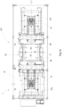
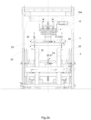
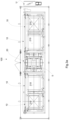
- FIG. 1 , 2 , and 3 an equipment 100 for making edged trays 200 starting from punched sheets 210 is depicted.
- Said equipment 100 comprises a feeding zone 1 to hold a plurality of said punched sheets 210, preferably arranged in a stack 250.
- Said equipment 100 further comprises a forming device 20.
- Said forming device 20 preferably comprises a forming die 2 and a corresponding punch 3 configured to form the tray 200 preferably by fitting into/disengaging from each other.
- This operation allows the deep drawing of the tray 200, i.e., it causes the folding of the flaps 203 and fins 202 defined by said creasing lines 211.
- the die 2 and the punch 3 preferably fit into/disengage from each other by a reciprocating rectilinear motion along a preferably vertical straight line.
- said movement of the die 2 and/or the punch 3 provides for a fixed stroke as a function of the height of the flaps 203.
- said movement of the die 2 and/or the punch 3 provides for a variable stroke as a function of the different type of tray 200 to be made, in particular as a function of the different height of the flaps 203.
- said stroke occurs in a controlled manner by a control unit U of the equipment 100.
- Said control unit U serves to manage also the other automatic operations provided for on the equipment 100.
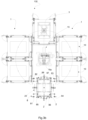
- a preferred embodiment provides for the equipment 100 to comprise at least one handling element 15 to transfer at least one of said punched sheets 210 from the feeding zone 1 on the forming device 20.
- Said handling element 15 can also be made by an anthropomorphic robot.
- Said die 2 is preferably configured to be positioned at operator-accessible height so as to facilitate an intervention, especially to solve forming issues.
- the forming device 20 may comprise even more than one die 2.
- the die 2 comprises forming walls 21, 22, 23, 24.
- Said forming walls 21, 22, 23, 24 are preferably located parallel to the four sides of the punched sheet 210.
- said forming walls 21, 22, 23, 24 are movable such as to be able to be brought to a working position that is suitable for the type and the dimensions of the tray 200 to be formed.
- Said forming walls 21, 22, 23, 24 shall be preferably positioned substantially at the creasing lines 211 onto which the folding of the flaps 203 can be carried out.
- Said forming walls 21, 22, 23, 24 are preferably configured to translate away from/closer to each other.
- said forming walls 21, 22, 23, 24 preferably remain stationary in the same position, while a displacement is needed when the format of the punched sheet 210 to be processed changes.
- the punch 3 comprises forming members 31, 32, 33, 34.
- Said forming members 31, 32, 33, 34 are in particular positioned parallel to the four sides of the punched sheet 210.
- forming members 31, 32, 33, 34 can be parallel to any bevels that are present between the sides of the punched sheet 210.
- Said forming members 31, 32, 33, 34 are preferably parallel to the forming walls 21, 22, 23, 24 of the die 2.
- said forming members 31, 32, 33, 34 are movable so as to be able to be brought to a working position that is suitable for the type and the dimensions of the tray 200 to be formed.
- Said forming members 31, 32, 33, 34 must preferably be positioned substantially at the creasing lines 211 onto which the folding of the flaps 203 is to be carried out.
- Said forming members 31, 32, 33, 34 are preferably configured to translate away from/closer to each other.
- said forming members 31, 32, 33, 34 remain preferably stationary in the same position, while a displacement is needed when the format of the punched sheet 210 to be processed changes.
- a preferred embodiment depicted in the figure provides for the die 2 to be in a stationary position and the punch 3 is movable with a reciprocating rectilinear motion, adapted to act as a pusher for the forced insertion of said sheet 210 into said forming walls 21, 22, 23, 24.
- said punch 3 comprises fluidic suctioning means 35.
- Said fluidic suctioning means 35 grip the punched sheet 210.
- the punch 3 retains said punched sheet 210 during its movement inside the die 2.
- Said fluidic suctioning means 35 can be suction cups 35', as depicted in the figure.
- said fluidic suctioning means 35 are movable so as to be able to be brought in a working position that is suitable for the type and the dimensions of the tray 200 to be formed.
- said fluidic suctioning means 35 are configured to translate away from/closer to each other.
- said fluidic suctioning means 35 preferably remain stationary in the same position, while a displacement can be needed when the format of the punched sheet 210 to be processed changes, in particular when the dimensions of the base 201 change.
- said fluidic suctioning means 35 are installed on the forming members 31, 32, 33, 34.
- Said fluidic suctioning means 35 can be movable integrally with the forming members 31, 32, 33, 34.
- said fluidic suctioning means 35 can be mechanically associated with the forming members 31, 32, 33, 34 of the punch 3.
- the forming device 20 comprises auxiliary means 8 to fold and/or fix flaps 203 and/or fins 202 of said punched sheet 210 being processed.
- Said auxiliary means 8 preferably comprise folding members 85, 86, 87, 88 to fold the fins 203 on the flap 202 before the fixing thereof.
- said folding members 85, 86, 87, 88 are movable so as to be able to be brought in a working position that is suitable for the type and dimensions of the tray 200 to be formed.
- folding members 85, 86, 87, 88 are configured to translate away from/closer to each other.
- said folding members 85, 86, 87, 88 preferably remain stationary in the same position, while a displacement is needed when the format of the punched sheet 210 to be processed changes.
- said folding members 85, 86, 87, 88 are installed on the forming die 2.
- Said folding members 85, 86, 87, 88 can be movable integrally with the forming walls 21, 22, 23, 24.
- folding members 85, 86, 87, 88 can be mechanically associated with the forming walls 21, 22, 23, 24 of the die 2.
- said auxiliary means 8 comprise locking members 81, 82, 83, 84 to fix said flaps 203 to the fins 202.
- the securing may preferably occur by means of interlocking and/or adhesive bonding and/or staple locking.
- said locking members 81, 82, 83, 84 as a function of the type of securing provided for on the tray 200 can comprise glue guns, as depicted in the figure, when the tray provides for a securing between fin 202 and flap 203 by using glue.
- said locking members 81, 82, 83, 84 can be actuators configured to exert an interlocking action, for example, of a portion of the fin 202 in a length of a flap 203, or vice versa, when the type of securing provided for on the tray 200 is an interlocking one.
- said locking members 81, 82, 83, 84 can comprise staple guns to insert a staple between a portion of the fin 202 and a length of a flap 203, when the type of securing provided for on the tray 200 is by means of staples.
- said locking members 81, 82, 83, 84 are movable so as to be able to be brought in a working position that is suitable for the type and the dimensions of the tray 200 to be formed.
- said locking members 81, 82, 83, 84 are configured to translate away from/closer to each other.
- said locking members 81, 82, 83, 84 preferably remain stationary in the same position, while a displacement is needed when the format of the punched sheet 210 to be processed changes.
- said locking members 81, 82, 83, 84 are installed on the forming die 2.
- Said locking members 81, 82, 83, 84 can be movable integrally with the forming walls 21, 22, 23, 24.
- the forming device 20 comprises a centering device 4 to center the punched sheet 210 prior to the forming of the tray 200.
- said centering device 4 may comprise holding members 41, 42, 43, 44 that are opposite each other in pairs, which, by a relative displacement, contact the sides of said punched sheet 210.
- the displacement of said holding members 41, 42, 43, 44 preferably takes place at each forming cycle, not only upon a format change.
- said centering device 4 is driven by the control unit U during the operational cycle of the equipment 100 to position said holding members 41, 42, 43, 44 at a corresponding size as a function of the dimensions of the base 201 of the tray 200.
- the centering device 4 can coincide with the die 2, in particular the holding members 41, 42, 43, 44 coincide with the forming walls 21, 22, 23, 24.
- the subject matter of the invention is an equipment 100 in which said feeding zone 1 comprises a plurality of magazines 10.
- each of said magazines 10 is configured to hold punched sheets 210 of different dimensions or types, preferably arranged on top of each other to form a stack 250.
- Said magazines 10 can be configured so that the loading of the stack 250 therein occurs automatically, for example, fed by a line of conveyors.
- they can be ground magazines 10, i.e., configured so that the insertion of the stack 250 takes place directly by a forklift and/or LGV.
- Such plurality of magazines 10 allows having different punched sheets 210 available for forming, which will be selected based on the requirements of the machines downstream or, in general, the production needs.
- the at least one element 15 is preferably configured to be ale to pick up the punched sheets 210 from each magazine 10.
- Said handling element 15 preferably comprises activating means 15a to rotate and/or translate parallel to the working plane at the magazines 10 and the forming device 20, in particular of the die 2.
- the equipment 100 may include two or more handling elements 15.
- Said one or more handling elements 15 can also be configured to handle edges and/or thermoformed items and/or already-formed trays or caps, possibly even manually fed at one or more magazines 10.
- the forming device 20 comprises more than one die 2, multiple handling elements 15 could be provided, each capable of interfacing with a specific die 2.
- the punch 3 can be installed on the handling element 15.
- the subject matter of the invention is also the forming device 20 comprising adjusting means 5, 6, 7 to adapt the dimensions thereof to the different sizes of a punched sheet 210 and of the corresponding tray 200 to be formed.
- said adjusting means 5, 6, 7 are driven by the control unit U, which manages the operation of the equipment 100
- said adjusting means 5, 6, 7 comprise a first adjusting device 5, to adapt the dimensions of the die 2.
- said adjusting means 5, 6, 7 comprise a second adjusting device 6, to adapt the dimensions of the punch 3.
- said adjusting means 5, 6, 7 preferably comprise a third adjusting device 7 to adapt the position of the auxiliary means 8.
- said adjusting means 5, 6, 7 comprise respective actuations, for example, electric or pneumatic motors or actuators and possible transmission means to adapt in an automatic manner the dimensions of the die 2 and/or the punch 3, and/or of the auxiliary means 8.
- the first adjusting device 5, and/or the second adjusting device 6, and/or the third adjusting device 7 are driven by the control unit U to respectively adapt the dimensions of the die 2, and/or the dimensions of the punch 3, and/or to adapt the position of the auxiliary means 8, during the operational cycle of the equipment 100.
- the forming walls 21, 22, 23, 24 of the die 2 are mechanically associated with the first adjusting device 5 driven by the control unit U preferably during the operational cycle of the equipment 100 to position them at a corresponding size as a function of the dimensions of the base 201 of the tray 200.
- the forming members 31, 32, 33, 34 and/or means of the punch 3 are mechanically associated with the second adjusting device 6 driven by the control unit U preferably during the operational cycle of the equipment 100 to position them at a corresponding size as a function of the dimensions of the base 201 of the tray 200.
- the second adjusting device 6 activates the translation of the forming members 31, 32, 33, 34 away from/closer to each other.
- said forming members 31, 32, 33, 34 preferably remain stationary in the same position during the operational forming cycle of the tray 200 and the control unit U does not activate the second adjusting device 6.
- the displacement may be needed when the format of the punched sheet 210 to be processed changes, in particular when the dimensions of the base 201 change, in which case, via the control unit, the second adjusting device 6 activates the translation of the forming members 31, 32, 33, 34 during the operational cycle of the equipment 100.
- the fluidic suctioning means 35 can be installed on the forming members 31, 32, 33, 34.
- Said fluidic suctioning means 35 can be movable integrally with the forming members 31, 32, 33, 34.
- the second adjusting device 6 driven by the control unit U, that, by positioning the forming members 31, 32, 33, 34, locates said fluidic suctioning means 35 at a corresponding size as a function of the dimensions of the base 201 of the tray 200.
- the locking members 81, 82, 83, 84 and/or the folding members 85, 86, 87, 88 are mechanically associated with the third adjusting device 7 driven by a control unit U, preferably during the operational cycle of the equipment 100 to position them at a corresponding size as a function of the type, and the dimensions of the tray 200 to be formed.
- the third adjusting device 7 activates the translation of the locking members 81, 82, 83, 84 and/or of the folding members 85, 86, 87, 88 away from/closer to each other.
- said locking members 81, 82, 83, 84 and/or folding members 85, 86, 87, 88 preferably remain stationary in the same position during the operational forming cycle of the tray 200, and the control unit U does not activate the third adjusting device 7.
- the displacement may be needed when the format of the punched sheet 210 to be processed changes, in which case, via the control unit, the third adjusting device 7 activates the translation of the locking members 81, 82, 83, 84 and/or of the folding members 85, 86, 87, 88 during the operational cycle of the equipment 100.
- said locking members 81, 82, 83, 84 and/or folding members 85, 86, 87, 88 are installed on the forming die 2.
- Said locking members 81, 82, 83, 84 and/or folding members 85, 86, 87, 88 can be movable integrally with the forming walls 21, 22, 23, 24.
- said locking members 81, 82, 83, 84 and/or folding members 85, 86, 87, 88 can be mechanically associated with the forming walls 21, 22, 23, 24 of the die 2.
- the first adjusting device 5 driven by the control unit U that, by positioning the forming walls 21, 22, 23, 24, locates said locking members 81, 82, 83, 84 and/or folding members 85, 86, 87, 88 at a corresponding size as a function of the dimensions of the base 201 of the tray 200.
- Said control unit U is configured to manage a plurality of recipes, each relating to a corresponding punched sheet 210 or tray 200.
- control unit U drives the handling element 15 so that it positions itself on the magazine 10 containing the punched sheet 210 suitable for making the required tray 200.
- Said control unit U drives the forming device 20 so that both the die 2 and the punch 3 adjust all their parts to receive and form the punched sheet 210 to be picked up, in particular the forming walls 21, 22, 23, 24, the forming members 31, 32, 33, 34, the folding members 85, 86, 87, 88, and/or the locking members 81, 82, 83, 84.
- Said control unit U provides for preferably executing these controls during the operational cycle of the equipment 100, in order to switch from a punched sheet 210 to another continuously, without having to stop the equipment 100.
- the handling element 15 picks up from the magazine 10 the punched sheet 210 suitable to make the required tray 200 and brings it to the die 2.
- the forming members 31, 32, 33, 34 In the case where the punch 3 is installed on the handling element 15 before picking up the sheet 210, the forming members 31, 32, 33, 34, must have been positioned as driven by the control unit U, according to the dimensions of the punched sheet 210 to be formed.
- the fluidic suctioning means 35 of the punch 3 release the sheet 210 on the die 2, and said sheet 210 is centered by the centering device 4.
- the fluidic suctioning means 35 can take charge of the sheet 210 again, and the punch 3 is inserted into the die 2 by a rectilinear motion along a preferably vertical straight line, performing a stroke that is preferably based on the height of the flaps 203 of the tray 200.
- the auxiliary means 8 intervene in order to complete the forming of the tray 200.
- Said method provides for forming trays 200 of different dimensions or types by picking up punched sheets 210 of different dimensions or types from a plurality of magazines 10.
- Said method preferably provides for adapting the forming device 20 to the different sizes and configurations of the punched sheet 210 and of the corresponding tray 200 to be formed.
- said method provides for adapting the forming device 20 during the operational cycle, to the different sizes of a punched sheet 210 and of the corresponding tray 200 to be formed.
Landscapes
- Making Paper Articles (AREA)
Applications Claiming Priority (1)
| Application Number | Priority Date | Filing Date | Title |
|---|---|---|---|
| IT102023000019533A IT202300019533A1 (it) | 2023-09-22 | 2023-09-22 | Apparecchiatura per la realizzazione di vassoi bordati di dimensioni o tipologie diverse |
Publications (1)
| Publication Number | Publication Date |
|---|---|
| EP4527607A1 true EP4527607A1 (fr) | 2025-03-26 |
Family
ID=89157969
Family Applications (1)
| Application Number | Title | Priority Date | Filing Date |
|---|---|---|---|
| EP24201718.4A Pending EP4527607A1 (fr) | 2023-09-22 | 2024-09-20 | Équipement pour la fabrication de barquettes à rebords de différentes dimensions ou de différents types |
Country Status (2)
| Country | Link |
|---|---|
| EP (1) | EP4527607A1 (fr) |
| IT (1) | IT202300019533A1 (fr) |
Citations (4)
| Publication number | Priority date | Publication date | Assignee | Title |
|---|---|---|---|---|
| US5024641A (en) * | 1987-03-06 | 1991-06-18 | Vega Automation | Programmable dynamically adjustable plunger and tray former apparatus |
| EP2363280A1 (fr) * | 2010-03-05 | 2011-09-07 | All Glass S.r.l. | Appareil et procédé pour la fabrication des barquettes d'emballage |
| WO2021062182A1 (fr) * | 2019-09-27 | 2021-04-01 | Intertape Polymer Corp. | Machine à encartonner pour de multiples configurations de cartons différentes et procédé d'utilisation |
| EP4147986A2 (fr) * | 2021-09-10 | 2023-03-15 | Lundgren Machinery AB | Procédé et dispositif pour la fabrication d'une boîte à double paroi à partir d'une ébauche à double paroi |
Family Cites Families (1)
| Publication number | Priority date | Publication date | Assignee | Title |
|---|---|---|---|---|
| ITMI20052218A1 (it) * | 2005-11-18 | 2007-05-19 | Bini Meccanica S R L | Apparecchiatura per la formatura di vassoi borsati a partire da fogli fustellati |
-
2023
- 2023-09-22 IT IT102023000019533A patent/IT202300019533A1/it unknown
-
2024
- 2024-09-20 EP EP24201718.4A patent/EP4527607A1/fr active Pending
Patent Citations (4)
| Publication number | Priority date | Publication date | Assignee | Title |
|---|---|---|---|---|
| US5024641A (en) * | 1987-03-06 | 1991-06-18 | Vega Automation | Programmable dynamically adjustable plunger and tray former apparatus |
| EP2363280A1 (fr) * | 2010-03-05 | 2011-09-07 | All Glass S.r.l. | Appareil et procédé pour la fabrication des barquettes d'emballage |
| WO2021062182A1 (fr) * | 2019-09-27 | 2021-04-01 | Intertape Polymer Corp. | Machine à encartonner pour de multiples configurations de cartons différentes et procédé d'utilisation |
| EP4147986A2 (fr) * | 2021-09-10 | 2023-03-15 | Lundgren Machinery AB | Procédé et dispositif pour la fabrication d'une boîte à double paroi à partir d'une ébauche à double paroi |
Also Published As
| Publication number | Publication date |
|---|---|
| IT202300019533A1 (it) | 2025-03-22 |
Similar Documents
| Publication | Publication Date | Title |
|---|---|---|
| US10239650B2 (en) | Packaging boxes with centring tab, cutouts and set of cutouts, method and device for producing such boxes | |
| US10759133B2 (en) | Machine for automatically manufacturing customized packaging items | |
| JP5717216B2 (ja) | 梱包箱用のカットアウトを移送する方法および装置 | |
| CN109715502B (zh) | 用于抓取和折叠插入板的头部、插入装置、填充站以及用于抓取、折叠和装载插入板的方法 | |
| JP6656306B2 (ja) | 箱組立ておよび梱包システム並びにそのシステム用コントローラ | |
| US10633136B2 (en) | Method and machine for closing square or rectangular cross-section boxes by reducing the height of same to that of the contents thereof | |
| US20140371045A1 (en) | Device and Method for Preparing Packaging Boxes With Vertical Unstacking | |
| US20240359420A1 (en) | Methods and machine for forming containers having top flange with glued corners | |
| DK2539160T3 (en) | Method and apparatus for embossing the characteristics of motor vehicles | |
| CN106586133B (zh) | 一种多规格快递箱包装一体机 | |
| RS57761B1 (sr) | Postupak i uređaj za formiranje kutije od talasastog kartona oko umetka sa referentnom ivicom | |
| US20170157880A1 (en) | Machine and method for folding and adhesively bonding blanks for the production of folding boxes | |
| EP4527607A1 (fr) | Équipement pour la fabrication de barquettes à rebords de différentes dimensions ou de différents types | |
| CN213736021U (zh) | 一种手机壳自动包装设备 | |
| US10913624B2 (en) | Device for grasping insert sheets, loading device, station for receiving blanks and machine for processing elements in the form of sheets | |
| EP0241916B1 (fr) | Dispositif pour dresser des ébauches de récipients d'emballage | |
| US10501221B2 (en) | Device and method for extraction | |
| EP3819240B1 (fr) | Empaqueteur de carton et procédé de transport d'une ébauche | |
| CN116890476A (zh) | 物料贴合机 | |
| GB2092059A (en) | Assembling a partitioned case | |
| EP3930969B1 (fr) | Ensemble de manipulation robotisé | |
| EP3842224A1 (fr) | Outil de formage pour emballages secondaires | |
| EP1068947B1 (fr) | Procédé pour la fabrication automatique des cartons à partir de matériel plat | |
| CN223002406U (zh) | 一种纸板类产品自动上料装置 | |
| EP1787793B1 (fr) | Dispositif pour former un plateau à partir d'un flan |
Legal Events
| Date | Code | Title | Description |
|---|---|---|---|
| PUAI | Public reference made under article 153(3) epc to a published international application that has entered the european phase |
Free format text: ORIGINAL CODE: 0009012 |
|
| STAA | Information on the status of an ep patent application or granted ep patent |
Free format text: STATUS: THE APPLICATION HAS BEEN PUBLISHED |
|
| AK | Designated contracting states |
Kind code of ref document: A1 Designated state(s): AL AT BE BG CH CY CZ DE DK EE ES FI FR GB GR HR HU IE IS IT LI LT LU LV MC ME MK MT NL NO PL PT RO RS SE SI SK SM TR |
|
| STAA | Information on the status of an ep patent application or granted ep patent |
Free format text: STATUS: REQUEST FOR EXAMINATION WAS MADE |
|
| 17P | Request for examination filed |
Effective date: 20250911 |
|
| RAV | Requested validation state of the european patent: fee paid |
Extension state: GE Effective date: 20250911 Extension state: MA Effective date: 20250911 Extension state: MD Effective date: 20250911 Extension state: TN Effective date: 20250911 |
|
| RAX | Requested extension states of the european patent have changed |
Extension state: BA Payment date: 20250911 |
|
| P01 | Opt-out of the competence of the unified patent court (upc) registered |
Free format text: CASE NUMBER: UPC_APP_8669_4527607/2025 Effective date: 20251001 |