EP4527745A2 - Verfahren und system zur herstellung eines aerostaten mit einer starken struktur und durch dieses verfahren hergestellter schwerlast-aerostat - Google Patents
Verfahren und system zur herstellung eines aerostaten mit einer starken struktur und durch dieses verfahren hergestellter schwerlast-aerostat Download PDFInfo
- Publication number
- EP4527745A2 EP4527745A2 EP25156359.9A EP25156359A EP4527745A2 EP 4527745 A2 EP4527745 A2 EP 4527745A2 EP 25156359 A EP25156359 A EP 25156359A EP 4527745 A2 EP4527745 A2 EP 4527745A2
- Authority
- EP
- European Patent Office
- Prior art keywords
- aerostat
- lifting
- airship
- hold
- current state
- Prior art date
- Legal status (The legal status is an assumption and is not a legal conclusion. Google has not performed a legal analysis and makes no representation as to the accuracy of the status listed.)
- Pending
Links
Images


Classifications
-
- B—PERFORMING OPERATIONS; TRANSPORTING
- B64—AIRCRAFT; AVIATION; COSMONAUTICS
- B64B—LIGHTER-THAN AIR AIRCRAFT
- B64B1/00—Lighter-than-air aircraft
- B64B1/58—Arrangements or construction of gas-bags; Filling arrangements
-
- B—PERFORMING OPERATIONS; TRANSPORTING
- B64—AIRCRAFT; AVIATION; COSMONAUTICS
- B64F—GROUND OR AIRCRAFT-CARRIER-DECK INSTALLATIONS SPECIALLY ADAPTED FOR USE IN CONNECTION WITH AIRCRAFT; DESIGNING, MANUFACTURING, ASSEMBLING, CLEANING, MAINTAINING OR REPAIRING AIRCRAFT, NOT OTHERWISE PROVIDED FOR; HANDLING, TRANSPORTING, TESTING OR INSPECTING AIRCRAFT COMPONENTS, NOT OTHERWISE PROVIDED FOR
- B64F5/00—Designing, manufacturing, assembling, cleaning, maintaining or repairing aircraft, not otherwise provided for; Handling, transporting, testing or inspecting aircraft components, not otherwise provided for
- B64F5/10—Manufacturing or assembling aircraft, e.g. jigs therefor
-
- B—PERFORMING OPERATIONS; TRANSPORTING
- B64—AIRCRAFT; AVIATION; COSMONAUTICS
- B64B—LIGHTER-THAN AIR AIRCRAFT
- B64B1/00—Lighter-than-air aircraft
- B64B1/06—Rigid airships; Semi-rigid airships
- B64B1/08—Framework construction
Definitions
- the present invention relates to a method for manufacturing an aerostat with a rigid structure. It also relates to a system for manufacturing an aerostat, as well as a heavy-duty aerostat manufactured by implementing this method.
- the field of the invention is more particularly, but not limited to, that of rigid-structured dirigible balloons, in particular that of heavy-load carrying dirigibles.
- the present invention relates to a method of manufacturing airships.
- the method proposes to build the airship in successive horizontal sections, starting from the upper horizontal section.
- the entire structure of this section including the curved upper parts of the transverse circular beams, the stringers, the skin and all the fittings, is carried out on the floor of the hangar. Cables from the roof of the hangar are fixed at suitable points of the completed section, which is then lifted by means of suitable winches to which the cables are fixed.
- the upper horizontal section is raised to a height equal to the thickness of the section to be produced which is located below. The operation is repeated until the airship is completed.
- this equipment places strain on the building's structure; this equipment is not easily moved to other hangars, for example to be used for another aerostat. Furthermore, the parts being assembled are not mechanically held in place.
- One aim of the invention is in particular to remedy all or part of the aforementioned drawbacks.
- the step of transferring the current state of the structure from the lifting means to the support device can be carried out by lowering the current state of the structure by the lifting means and placing the current state of the structure in a rest state on the support device.
- the step of lifting the current state of the structure can be advantageously carried out by jacks, but also by lifting winches arranged above the structure being assembled. These two means can be used in combination.
- the lifting winches can be advantageously implemented from an assembly phase called the equator corresponding to the maximum width of the structure being assembled.
- the manufacturing method according to the invention further comprises a plurality of steps for connecting determined points of the upper part of the already assembled structure to determined points of the mechanical coupling beams of the hold structure to the structure,
- the erection system according to the invention may further advantageously comprise means for arranging a hold structure inside the structure being erected.
- the means for arranging the hold structure may include lifting tables on which the hold structure is placed.
- the assembly means may further be arranged to assemble the hold structure so as to mechanically couple it to the horizontal section being assembled by means of beams.
- the erection system according to the invention can then comprise means for connecting determined points of the upper part of the already assembled structure to determined points of the mechanical coupling beams of the hold structure to the structure
- the aerostat has a structure comprising a rigid skeleton covered with a flexible envelope and containing carrier gas balloons.
- the skeleton is an assembly of beams arranged in transverse frames and longitudinal stringers and stiffened by a system of tensioned elements.
- the carrier gas balloons are distributed along the length of the aerostat.
- this hold has a hold structure mechanically coupled to the structure of the aerostat, on the one hand, by a set of beams arranged transversely on either side of the hold structure and mechanically connected to lateral faces of said structure, and on the other hand by a set of cables stretched between points determined from said coupling beams and determined points of the upper part of said structure. This arrangement being carried out for the “main” frames separating the carrier gas balloons.
- the cross beams may advantageously comprise lattice beams made of pultruded carbon composite tubes, and the cables comprise solid-section composite rods made of pultruded carbon.
- the aerostat then comprises articulated connections of the cables to the coupling beams and to the upper part of the structure. These articulated connections may comprise metal parts.
- the beams between the hold structure and the main structure ensure the stability of the lower part.
- the cables stretched between these beams and the upper part of the main structure transmit the forces between the hold supporting the payload and the upper part supporting the lift forces resulting from the aerostatic pressure of the helium.
- the structure as a whole is self-supporting. It has the strength and stability to support its own weight and that of the various equipment without the presence of carrier gas.
- the self-supporting capacity of the structure also applies to the intermediate states of its assembly by successive horizontal sections. This capacity is made possible by an arrangement of rigid beams and tensioned elements around the perimeter of the main frames separating the carrier gas tanks.
- variants of the invention comprising only a selection of the characteristics described, subsequently isolated from the other characteristics described, if this selection of characteristics is sufficient to confer a technical advantage or to differentiate the invention compared to the state of the prior art.
- This selection comprises at least one characteristic, preferably functional without structural details, or with only a part of the structural details if this part only is sufficient to confer a technical advantage or to differentiate the invention compared to the state of the prior art.
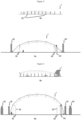
- Each of the figures 1 to 10 comprises a sub-figure a showing a front view of the current state of construction of the airship 1 and a sub-figure b showing a longitudinal view, from the left side, of the current state of construction of the airship 1.
- a manufacturing device 10 comprising two pluralities of lifting columns 20 and 20' rising from a surface of an assembly zone.
- the plurality of columns 20' are aligned on a left side of the airship while the plurality of columns 20 are aligned on a right side of the airship.
- Each 20 column corresponds to a 20' column in a transverse plane of the airship under construction.
- Each of the lifting columns has a forklift truck arranged to be mounted vertically and slide on the lifting column, with a travel of 10 meters, and to be controlled by a control handle in the form of a reinforced tiller or a pedal.
- the weight of the airship is distributed laterally over the lifting columns 20 and 20' and over the tripod 30 in the center.
- a step is described which follows the step described with reference to the Figure 1 .
- the airship is raised to a height suitable for the construction of the next horizontal section.
- the weight of the airship is distributed laterally on the lifting columns 20 and 20' at two support points, and freeing the tripod 30 which can be moved.
- the manufacturing device 10 comprises an additional 30' tripod.
- Tripods 30 and 30' are placed opposite two load recovery points of airship 1 suitably arranged near the ends supported by the two columns 20 and 20'.
- the airship is then placed on the tripods at each of its two load-recovery points.
- the lifting columns 20 and 20' are each moved into a second transverse position.
- this installation is carried out not only on a transverse part of the current section, but also along the entire longitudinal extent of the current section.
- FIG. 6 a step is described which follows the step described with reference to the Figure 5 .
- FIG. 6 has a sub- Figure 6a showing a front view of the current state of construction of airship 1 and a sub- Figure 6b showing a longitudinal view of the current state of construction of airship 1.
- this stage includes the installation of propulsion engines as well as the installation of the tail of airship 1.
- the manufacturing device 10 comprises additional lifting columns 50 and 50'.
- Each of the additional lifting columns has a forklift arranged to be mounted vertically and slide on the lifting column, with a travel of 25 meters, and to be controlled by a control handle in the form of a reinforced tiller or a pedal.
- each of the two tripods 30 and 30' is provided at its upper end with a vertical arm, or wick, or vertical rod, respectively 32 and 32'.
- step 8 a step is described which follows the step described with reference to the Figure 7 .
- hold 2 of airship 1 is moved under the structure erected until then.
- the manufacturing device 10 comprises lifting tables 60 and 60' on which the hold 2 rests.
- the additional lifting columns 50 and 50' raise the airship 1 so that the uppermost section of the lower part of the structure of the airship 1 can be fixed to the already erected structure as well as to the hold 2.
- each of the two tripods 30 and 30' is again placed with its arm under points raised above the ground, on which beam ends are to be fixed.
- various cables and stringers for fixing connecting parts are installed on the uppermost section of the lower part.
- the installation of the connecting cables 90 is particularly facilitated by the absence of the carrier gas, which limits the introduction of pretension.
- the envelope panels are also installed, as well as the communication networks and the positioning of the helium cell.
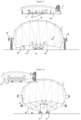
- a step is described which follows the step described with reference to the figure 9 .
- the structure of the airship 1 is completely completed and the hold 2 of the airship is attached to the structure of the airship.
- the structure of the airship comprises several transverse beams 80, as well as the connecting cables.
- the airship 1 is placed on a transport device 70, of the transport platform type having a plurality of wheels. It is then possible to carry out static tests on the terminal, but also to test the operation of winches, specific to the airship, which can be loaded into the hold for its operations, and which must therefore be tested.
- small columns provide geometric positioning, lifting and lowering of the load
- large columns provide support for the geometric positioning performed by the small columns, support of the load in X, Y, Z and also contribute to the lifting and lowering of the load.
- Lifting winches (not shown) are arranged inside the assembly unit on one or more mechanical structures overlooking the airship being assembled. These winches are attached to small columns.
- the small columns provide geometric positioning, load support in X, Y, Z, and lifting and lowering of the load, while the winches provide support for the geometric positioning performed by the small columns, load support in Z above the equator, and contribute to lifting and lowering of the load.
- the small columns ensure geometric positioning, load support in X, Y, Z, lifting and lowering of the load, while the winches ensure support for the geometric positioning performed by the small columns, load support in Z above the equator, and contribute to the lifting and lowering of the load.
Landscapes
- Engineering & Computer Science (AREA)
- Aviation & Aerospace Engineering (AREA)
- Manufacturing & Machinery (AREA)
- Mechanical Engineering (AREA)
- Transportation (AREA)
- Conveying And Assembling Of Building Elements In Situ (AREA)
- Automatic Assembly (AREA)
Applications Claiming Priority (3)
| Application Number | Priority Date | Filing Date | Title |
|---|---|---|---|
| FR1908229A FR3098786B1 (fr) | 2019-07-19 | 2019-07-19 | « Procédé et système de fabrication d'un aérostat à structure rigide, et aérostat porteur de charge lourde ainsi fabriqué » |
| EP20753994.1A EP3999413B1 (de) | 2019-07-19 | 2020-07-17 | Verfahren und system zur herstellung eines aerostaten mit einer starken struktur und durch dieses verfahren hergestellter schwerlast-aerostat |
| PCT/FR2020/051296 WO2021014082A1 (fr) | 2019-07-19 | 2020-07-17 | Procédé et système de fabrication d'un aérostat a structure rigide, et aérostat porteur de charge lourde ainsi fabriqué |
Related Parent Applications (2)
| Application Number | Title | Priority Date | Filing Date |
|---|---|---|---|
| EP20753994.1A Division EP3999413B1 (de) | 2019-07-19 | 2020-07-17 | Verfahren und system zur herstellung eines aerostaten mit einer starken struktur und durch dieses verfahren hergestellter schwerlast-aerostat |
| EP20753994.1A Division-Into EP3999413B1 (de) | 2019-07-19 | 2020-07-17 | Verfahren und system zur herstellung eines aerostaten mit einer starken struktur und durch dieses verfahren hergestellter schwerlast-aerostat |
Publications (2)
| Publication Number | Publication Date |
|---|---|
| EP4527745A2 true EP4527745A2 (de) | 2025-03-26 |
| EP4527745A3 EP4527745A3 (de) | 2025-05-07 |
Family
ID=68654677
Family Applications (2)
| Application Number | Title | Priority Date | Filing Date |
|---|---|---|---|
| EP20753994.1A Active EP3999413B1 (de) | 2019-07-19 | 2020-07-17 | Verfahren und system zur herstellung eines aerostaten mit einer starken struktur und durch dieses verfahren hergestellter schwerlast-aerostat |
| EP25156359.9A Pending EP4527745A3 (de) | 2019-07-19 | 2020-07-17 | Verfahren und system zur herstellung eines aerostaten mit einer starken struktur und durch dieses verfahren hergestellter schwerlast-aerostat |
Family Applications Before (1)
| Application Number | Title | Priority Date | Filing Date |
|---|---|---|---|
| EP20753994.1A Active EP3999413B1 (de) | 2019-07-19 | 2020-07-17 | Verfahren und system zur herstellung eines aerostaten mit einer starken struktur und durch dieses verfahren hergestellter schwerlast-aerostat |
Country Status (7)
| Country | Link |
|---|---|
| US (2) | US11981414B2 (de) |
| EP (2) | EP3999413B1 (de) |
| JP (1) | JP7482212B2 (de) |
| KR (1) | KR20220088843A (de) |
| CN (1) | CN114746332B (de) |
| FR (1) | FR3098786B1 (de) |
| WO (1) | WO2021014082A1 (de) |
Families Citing this family (1)
| Publication number | Priority date | Publication date | Assignee | Title |
|---|---|---|---|---|
| MX2024005984A (es) * | 2021-11-17 | 2024-08-27 | H2 Clipper Inc | Sistema, metodo y aparato mejorados para fabricacion de aerostatos usando robotica. |
Citations (1)
| Publication number | Priority date | Publication date | Assignee | Title |
|---|---|---|---|---|
| US1559807A (en) | 1925-01-16 | 1925-11-03 | Herbert V Thaden | Method of erecting airships |
Family Cites Families (9)
| Publication number | Priority date | Publication date | Assignee | Title |
|---|---|---|---|---|
| US1191077A (en) * | 1915-08-20 | 1916-07-11 | Oscar Hermanson | Airship. |
| US1651754A (en) * | 1920-09-10 | 1927-12-06 | Firm Luftschiffbau Zeppelin Gm | Auxiliary device for assembling airships |
| US3129911A (en) * | 1962-01-31 | 1964-04-21 | Aereon Corp | Framework for rigid aircraft |
| US4259776A (en) * | 1978-08-09 | 1981-04-07 | Airships International Inc. | Method of assembly of airship hull |
| US5823468A (en) * | 1995-10-24 | 1998-10-20 | Bothe; Hans-Jurgen | Hybrid aircraft |
| WO2000073142A2 (de) * | 1999-05-28 | 2000-12-07 | Uti Holding + Management Ag | Leichter-als-luft-flugapparat und verfahren zum steuern eines solchen flugapparats |
| JP3484537B2 (ja) | 2000-05-02 | 2004-01-06 | 川崎重工業株式会社 | 飛行船の骨材組立方法 |
| JP3708060B2 (ja) | 2002-03-20 | 2005-10-19 | 株式会社巴コーポレーション | 屋根構造物の構築方法 |
| CN109515677B (zh) | 2018-10-17 | 2022-04-19 | 中国特种飞行器研究所 | 一种浮空器艇体吊舱连接结构 |
-
2019
- 2019-07-19 FR FR1908229A patent/FR3098786B1/fr active Active
-
2020
- 2020-07-17 CN CN202080064210.0A patent/CN114746332B/zh active Active
- 2020-07-17 EP EP20753994.1A patent/EP3999413B1/de active Active
- 2020-07-17 US US17/597,684 patent/US11981414B2/en active Active
- 2020-07-17 WO PCT/FR2020/051296 patent/WO2021014082A1/fr not_active Ceased
- 2020-07-17 KR KR1020227005534A patent/KR20220088843A/ko not_active Ceased
- 2020-07-17 EP EP25156359.9A patent/EP4527745A3/de active Pending
- 2020-07-17 JP JP2022503840A patent/JP7482212B2/ja active Active
-
2024
- 2024-04-03 US US18/625,897 patent/US20240317380A1/en active Pending
Patent Citations (1)
| Publication number | Priority date | Publication date | Assignee | Title |
|---|---|---|---|---|
| US1559807A (en) | 1925-01-16 | 1925-11-03 | Herbert V Thaden | Method of erecting airships |
Also Published As
| Publication number | Publication date |
|---|---|
| CA3148036A1 (fr) | 2021-01-28 |
| JP7482212B2 (ja) | 2024-05-13 |
| US20230211866A1 (en) | 2023-07-06 |
| CN114746332B (zh) | 2025-06-13 |
| EP3999413C0 (de) | 2025-03-19 |
| CN114746332A (zh) | 2022-07-12 |
| FR3098786A1 (fr) | 2021-01-22 |
| KR20220088843A (ko) | 2022-06-28 |
| EP3999413A1 (de) | 2022-05-25 |
| JP2022540960A (ja) | 2022-09-20 |
| WO2021014082A1 (fr) | 2021-01-28 |
| EP3999413B1 (de) | 2025-03-19 |
| US11981414B2 (en) | 2024-05-14 |
| EP4527745A3 (de) | 2025-05-07 |
| US20240317380A1 (en) | 2024-09-26 |
| FR3098786B1 (fr) | 2021-08-06 |
Similar Documents
| Publication | Publication Date | Title |
|---|---|---|
| FR3109785A1 (fr) | équipement pour l’étaiement de planchers préfabriqués | |
| WO1983001235A1 (fr) | Dispositif flottant de levage et de transport de charge | |
| FR3048235A1 (fr) | Outillage pour l'integration d'un module dans un aeronef et procede d'integration associe | |
| EP3999413B1 (de) | Verfahren und system zur herstellung eines aerostaten mit einer starken struktur und durch dieses verfahren hergestellter schwerlast-aerostat | |
| EP3455156B1 (de) | Bewegliche basis und verfahren zum transport einer ausrüstung | |
| FR2969681A1 (fr) | Mat auto stable pour terrasse et procede d'installation dudit mat | |
| EP4049936B1 (de) | System mit einem beweglichen schlitten und verfahren zur anwendung eines solchen systems mit beweglichem schlitten | |
| CN116242202A (zh) | 一种运载火箭的测试发射方法 | |
| EP0511910B1 (de) | Hubschrauber-getragener Arbeitskorb und Verfahren zum Austausch einer Verbindungsmuffe eines Freileitungskabels | |
| CA3148036C (fr) | Procede et systeme de fabrication d'un aerostat a structure rigide, et aerostat porteur de charge lourde ainsi fabrique | |
| EP1571079A1 (de) | Rumpfholm für ein Flugzeug und Flügelmittelkasten mit einem solchen Rumpfholm | |
| US3010106A (en) | Mobile antenna structure and method of erecting same | |
| WO2025160314A1 (en) | Solar table mobile transport vehicle with rack | |
| EP3826922B1 (de) | System und verfahren zum festmachen eines luftfahrzeugs vom typ eines aerostats oder lenkballons | |
| CA2217997C (fr) | Dispositif pour faciliter le deplacement et le positionnement d'une piece cylindrique allongee | |
| BE1032673B1 (fr) | Procédé de construction de poutres en acier de type caisson séparé et de traverses pour un pont suspendu auto-ancré de grande portée | |
| US20250340381A1 (en) | Solar table rack with off-loader | |
| FR3058392A1 (fr) | Chariot et procede de transport d'un moteur d'aeronef | |
| WO2006070094A1 (fr) | Structure de local extensible et transportable | |
| CN118475769A (zh) | 用于操纵风力涡轮机的机舱的系统以及相关方法 | |
| BE375063A (de) | ||
| FR3079250A1 (fr) | Structure modulable d’un bungalow transportable et empilement de telles structures | |
| EP0072265A1 (de) | Transportierbare Tribüne | |
| FR2721582A1 (fr) | Installation pour le chargement, le déchargement et le transport d'objets lourds et encombrants à bord d'un véhicule tel qu'un aéronef. |
Legal Events
| Date | Code | Title | Description |
|---|---|---|---|
| PUAI | Public reference made under article 153(3) epc to a published international application that has entered the european phase |
Free format text: ORIGINAL CODE: 0009012 |
|
| STAA | Information on the status of an ep patent application or granted ep patent |
Free format text: STATUS: REQUEST FOR EXAMINATION WAS MADE |
|
| 17P | Request for examination filed |
Effective date: 20250206 |
|
| AC | Divisional application: reference to earlier application |
Ref document number: 3999413 Country of ref document: EP Kind code of ref document: P |
|
| AK | Designated contracting states |
Kind code of ref document: A2 Designated state(s): AL AT BE BG CH CY CZ DE DK EE ES FI FR GB GR HR HU IE IS IT LI LT LU LV MC MK MT NL NO PL PT RO RS SE SI SK SM TR |
|
| PUAL | Search report despatched |
Free format text: ORIGINAL CODE: 0009013 |
|
| AK | Designated contracting states |
Kind code of ref document: A3 Designated state(s): AL AT BE BG CH CY CZ DE DK EE ES FI FR GB GR HR HU IE IS IT LI LT LU LV MC MK MT NL NO PL PT RO RS SE SI SK SM TR |
|
| RIC1 | Information provided on ipc code assigned before grant |
Ipc: B64F 5/10 20170101AFI20250331BHEP |
|
| STAA | Information on the status of an ep patent application or granted ep patent |
Free format text: STATUS: EXAMINATION IS IN PROGRESS |
|
| 17Q | First examination report despatched |
Effective date: 20260216 |