EP4527751A1 - Dispositif d'étiquetage de récipients - Google Patents
Dispositif d'étiquetage de récipients Download PDFInfo
- Publication number
- EP4527751A1 EP4527751A1 EP24201866.1A EP24201866A EP4527751A1 EP 4527751 A1 EP4527751 A1 EP 4527751A1 EP 24201866 A EP24201866 A EP 24201866A EP 4527751 A1 EP4527751 A1 EP 4527751A1
- Authority
- EP
- European Patent Office
- Prior art keywords
- roll
- robot
- label
- tape
- unit
- Prior art date
- Legal status (The legal status is an assumption and is not a legal conclusion. Google has not performed a legal analysis and makes no representation as to the accuracy of the status listed.)
- Pending
Links
Images

Classifications
-
- B—PERFORMING OPERATIONS; TRANSPORTING
- B65—CONVEYING; PACKING; STORING; HANDLING THIN OR FILAMENTARY MATERIAL
- B65C—LABELLING OR TAGGING MACHINES, APPARATUS, OR PROCESSES
- B65C9/00—Details of labelling machines or apparatus
- B65C9/08—Label feeding
- B65C9/18—Label feeding from strips, e.g. from rolls
- B65C9/1892—Spools or cassettes for strips
-
- B—PERFORMING OPERATIONS; TRANSPORTING
- B65—CONVEYING; PACKING; STORING; HANDLING THIN OR FILAMENTARY MATERIAL
- B65C—LABELLING OR TAGGING MACHINES, APPARATUS, OR PROCESSES
- B65C9/00—Details of labelling machines or apparatus
- B65C9/26—Devices for applying labels
-
- B—PERFORMING OPERATIONS; TRANSPORTING
- B25—HAND TOOLS; PORTABLE POWER-DRIVEN TOOLS; MANIPULATORS
- B25J—MANIPULATORS; CHAMBERS PROVIDED WITH MANIPULATION DEVICES
- B25J11/00—Manipulators not otherwise provided for
- B25J11/005—Manipulators for mechanical processing tasks
-
- B—PERFORMING OPERATIONS; TRANSPORTING
- B25—HAND TOOLS; PORTABLE POWER-DRIVEN TOOLS; MANIPULATORS
- B25J—MANIPULATORS; CHAMBERS PROVIDED WITH MANIPULATION DEVICES
- B25J13/00—Controls for manipulators
- B25J13/08—Controls for manipulators by means of sensing devices, e.g. viewing or touching devices
- B25J13/086—Proximity sensors
-
- B—PERFORMING OPERATIONS; TRANSPORTING
- B25—HAND TOOLS; PORTABLE POWER-DRIVEN TOOLS; MANIPULATORS
- B25J—MANIPULATORS; CHAMBERS PROVIDED WITH MANIPULATION DEVICES
- B25J15/00—Gripping heads and other end effectors
- B25J15/0047—Gripping heads and other end effectors for internally gripping hollow or recessed objects
-
- B—PERFORMING OPERATIONS; TRANSPORTING
- B25—HAND TOOLS; PORTABLE POWER-DRIVEN TOOLS; MANIPULATORS
- B25J—MANIPULATORS; CHAMBERS PROVIDED WITH MANIPULATION DEVICES
- B25J15/00—Gripping heads and other end effectors
- B25J15/04—Gripping heads and other end effectors with provision for the remote detachment or exchange of the head or parts thereof
-
- B—PERFORMING OPERATIONS; TRANSPORTING
- B65—CONVEYING; PACKING; STORING; HANDLING THIN OR FILAMENTARY MATERIAL
- B65C—LABELLING OR TAGGING MACHINES, APPARATUS, OR PROCESSES
- B65C9/00—Details of labelling machines or apparatus
- B65C9/08—Label feeding
- B65C9/18—Label feeding from strips, e.g. from rolls
-
- B—PERFORMING OPERATIONS; TRANSPORTING
- B65—CONVEYING; PACKING; STORING; HANDLING THIN OR FILAMENTARY MATERIAL
- B65H—HANDLING THIN OR FILAMENTARY MATERIAL, e.g. SHEETS, WEBS, CABLES
- B65H19/00—Changing the web roll
- B65H19/10—Changing the web roll in unwinding mechanisms or in connection with unwinding operations
- B65H19/12—Lifting, transporting, or inserting the web roll; Removing empty core
-
- B—PERFORMING OPERATIONS; TRANSPORTING
- B65—CONVEYING; PACKING; STORING; HANDLING THIN OR FILAMENTARY MATERIAL
- B65C—LABELLING OR TAGGING MACHINES, APPARATUS, OR PROCESSES
- B65C9/00—Details of labelling machines or apparatus
- B65C2009/0081—Means for forming a label web buffer, e.g. label web loop
-
- B—PERFORMING OPERATIONS; TRANSPORTING
- B65—CONVEYING; PACKING; STORING; HANDLING THIN OR FILAMENTARY MATERIAL
- B65H—HANDLING THIN OR FILAMENTARY MATERIAL, e.g. SHEETS, WEBS, CABLES
- B65H2555/00—Actuating means
- B65H2555/30—Multi-axis
Definitions
- the invention relates to a device for labeling containers with a supply device for supplying a labeling device with a label strip for labeling containers.
- a container handling system may include a labeling device for labeling containers.
- the labeling device can label the containers with labels from a label roll (roll of label material).
- the label rolls are manually loaded by an operator.
- the operator may also be required to perform additional tasks, such as cutting the label strip to the correct position, applying double-sided adhesive tape to the label strip, or feeding the label strip into an automatic gluing system.
- the DE 10 2021 125 133 A1 describes a mobile robot, a supply system, and a method for changing label rolls on a labeling unit for labeling containers.
- the mobile robot comprises a vehicle unit for relocating the robot and a manipulator unit with a multi-axis manipulator and an associated end effector for manipulating label rolls. Because the end effector is designed to grip the label rolls and empty label roll cores around their outer circumference, ergonomically problematic work steps when reloading label rolls can be performed exclusively by machine, with great precision, and in a way that protects the material.
- the EP 3 760 550 A1 describes a transfer unit for feeding rolls of labeling material to a labeling module configured to apply labels to objects.
- the transfer unit comprises a support member configured to support a plurality of rolls arranged vertically in at least one stack.
- the transfer unit further comprises a robot arm configured to remove at least one roll at a time from the stack at a gripping station and to release it at a release station.
- the invention is based on the object of creating an improved supply of a labeling device with label rolls.
- the device comprises a labeling device, preferably a rotary labeling device, with a labeling unit for labeling the containers.
- the device comprises a supply device connected to the labeling unit for feeding a label strip to the labeling unit.
- the supply device comprises a robot cell arranged at a distance from the labeling unit.
- the robot cell comprises a roll storage unit for depositing label rolls.
- the robot cell further comprises a roll receiving device for receiving and unwinding at least one label roll onto the label strip for feeding to the labeling unit.
- the robot cell further comprises a robot (e.g., with or without collaboration functionality), preferably a multi-axis robot, particularly preferably an articulated-arm robot.
- the robot is configured to automatically load the roll receiving device with label rolls from the roll storage unit.
- the device can advantageously enable a very high degree of automation.
- the robot can advantageously perform as many tasks as possible, instead of specialized automated individual devices, which can result in particular in cost and flexibility advantages.
- the device advantageously enables accessibility to the labeling unit due to the spaced arrangement not to be impaired by the robot, etc. This allows, for example, maintenance or adjustment work on the labeling unit to be carried out without great effort and with very good accessibility. It is also advantageous that, as in the prior art, DE 10 2021 125 133 A1 It is necessary to keep the area directly in front of the labeling unit meticulously clear to always provide a parking space for the mobile robot.
- the robot cell can also enable high-performance supply equipment, which can, for example, also supply more than one labeling device.
- the robot cell allows for the installation of multiple roll-holding devices, as there are no cramped spaces like those directly at the labeling unit.
- the supply device further comprises a label strip buffer, which is connected to the roll take-up device for receiving the label strip from the roll take-up device and to the labeling unit for feeding the label strip to the labeling unit.
- the label strip buffer is designed to buffer the received label strip and to unload the buffered label strip for feeding to the labeling unit.
- the label strip buffer can preferably be arranged inside or outside an optional protective housing of the robot cell. Advantageously, this can ensure a continuous supply of label strip even when, for example, two label strips are currently being joined together.
- the device further comprises a tape guide bridge that connects the supply device and the labeling unit for guiding the label tape to the labeling unit.
- the tape guide bridge can preferably be arranged outside an optional protective housing of the robot cell.
- the tape guide bridge can easily enable the supply of the spaced-apart labeling unit without blocking travel or movement paths between the labeling unit and the supply device.
- the robot cell is spaced from the labeling unit at least far enough for the labeling unit to be decoupled from the labeling device and moved away (e.g., pushed away).
- a minimum distance between the robot cell and the labeling unit can be ⁇ 1 m, ⁇ 1.5 m, ⁇ 2 m, ⁇ 3 m, ⁇ 4 m, or ⁇ 5 m.
- a walking or driving path can run between the robot cell and the labeling unit.
- the labeling device comprises a further labeling unit for labeling the containers.
- the supply device is connected to the further labeling unit for feeding a further label strip to the further labeling unit.
- the robot cell is arranged at a distance from the further labeling unit and further comprises a further roll receiving device for receiving and unwinding at least one further label roll onto the further label strip for feeding to the further labeling unit.
- the robot is configured to automatically load the further roll receiving device with label rolls from the roll storage.
- a single robot can thus supply several labeling units with label rolls.
- the robot cell enables This means that the robot does not have to move between two labeling units, which is laborious and time-consuming. Instead, the robot can advantageously supply the labeling units from a single position. The robot cell can thus enable a high overall performance of the supply system.
- the roll receiving device and the further roll receiving device are each aligned towards the robot, preferably each radially relative to a (e.g., stationary) base of the robot, and/or each equidistant from the robot.
- the robot can thus perform essentially the same movement to load the roll receiving devices, so that essentially a single programming for this robot movement is sufficient to load multiple roll receiving devices and also to cover a variety of configurations of the robot cell (e.g., stationary robot, robot on a linear axis, variable position of the roll receiving devices, different number of roll receiving devices, etc.). If the robot is movably mounted, for example, on a linear axis, the robot base has a variety of working positions, and the distance and orientation of the roll receiving devices can therefore be variable within certain limits.
- the roll receiving device and/or the further roll receiving device (each) has two, preferably horizontally or vertically aligned, roll receptacles, preferably roller plates, and a connector designed to connect a tape end of a label roll from one of the two roll receptacles to a tape start of a label roll from the other of the two roll receptacles.
- the robot can further be configured to feed the tape start to the connector and/or to apply an adhesive tape to the tape start. This can advantageously enable an uninterrupted supply of label tapes and a secure and quickly established connection of the label tapes.
- a horizontal alignment of the roll receptacles can advantageously facilitate loading by the robot.
- the robot cell further comprises a protective housing that encloses the roll storage, the roll receiving device, and the robot.
- the robot cell further comprises a system for generating at least one signal curtain, preferably a light curtain or laser curtain, for delimiting the robot cell (e.g., on one side or on multiple sides).
- the system is designed to generate a signal curtain in front of the roll storage to make the roll storage accessible from outside the robot cell.
- the protective housing and/or the signal curtain can enable very high speed and dynamics of the robot, since there is no danger to persons in the surrounding area. This allows the robot cell to be operated at very high power, which can, for example, supply more than one labeling device.
- a signal curtain can be used to simplify loading the roll storage with label rolls, for example using a pallet truck or an automated guided vehicle (AGV).
- AGV automated guided vehicle
- the robot cell further comprises a tool changing station, which is preferably arranged within an optional protective housing of the robot cell.
- the robot is configured to perform an automatic tool change at the tool changing station.
- the robot can be configured to perform an automatic tool change at the tool changing station between different handling tools, preferably comprising at least one roll handling tool, preferably an internal roll gripper, for handling a label roll and/or at least one tape start handling tool. for handling the beginning of a label roll.
- the robot can therefore advantageously use different gripper types and different grippers of the same type (e.g., different beginning of the label roll grippers for low and high label rolls).
- the robot is a stationary robot, or the robot is movable within the robot cell, preferably along a linear axis and/or rail-guided.
- the roll receiving device can (also) be manually loaded with a label roll.
- the robot cell can further comprise an (obstacle-free) personnel movement area located between the roll storage and the roll receiving device, allowing an operator to manually load the roll receiving device with a label roll (e.g., if the robot is defective, undergoing maintenance, or deactivated).
- the robot cell further comprises a label roll buffer for the temporary storage of inspected label rolls, which buffer is preferably arranged within an optional protective housing of the robot cell. This advantageously allows for the temporary storage of inspected label rolls.
- the robot is configured to turn a label roll depending on a winding direction of the respective label roll, which has been previously detected by a testing device.
- the robot can thus enable the label roll to be fed to the roll receiving device with the correct winding direction, without the need for special Measures must be taken to ensure that the label rolls are placed on the roll holder with the correct orientation.
- the robot has an adhesive tape dispenser for dispensing a preferably double-sided adhesive tape for connecting label strips.
- an adhesive tape dispenser for dispensing a preferably double-sided adhesive tape for connecting label strips.
- the robot can be operated as a cobot, for example, allowing work to continue at a reduced robot speed even when the robot cell's protective enclosure is open.
- the supply device can be modular in design, and/or the at least one roll-holding device and the robot each have their own control device.
- the modularity can enable the construction of different supply devices with different levels of automation.
- each component can have its own control device, which advantageously improves modularity and simplifies subsequent modifications or upgrades.
- a further aspect of the present disclosure relates to a container treatment plant (e.g. for tempering, manufacturing, cleaning, coating, testing, filling, closing, pasteurizing, labeling, printing, marking, laser marking and/or packaging containers for liquid or pasty media, preferably beverages, liquid foodstuffs, or products from the pharmaceutical or healthcare industry).
- the container treatment system may comprise the labeling device as disclosed herein.
- the containers can be designed as bottles, cans, canisters, cartons, flacons, tubes, etc.
- control device can refer to electronics (e.g., implemented as a driver circuit or with microprocessor(s) and data memory) and/or a mechanical, pneumatic, and/or hydraulic control system, which, depending on its design, can perform control tasks and/or regulation tasks and/or processing tasks. Even if the term “control” is used herein, it can also appropriately include or mean “regulation” or “control with feedback” and/or “processing.”
- the Figure 1 shows a device 10 for labeling containers.
- the device 10 has a labeling device 12 and a supply device 24.
- the device 10 can be incorporated into a container processing system.
- the labeling device 12 can label containers.
- the labeling device 12 can have at least one labeling unit 14, 16.
- the at least one labeling unit 14, 16 can be configured to apply labels from a label strip to the containers.
- the at least one labeling unit 14, 16 can be interchangeably coupled and uncoupled from a periphery of the labeling device 12, e.g., via a preferably tool-free quick-coupling mechanism.
- a plurality of labeling units 14, 16 are included, positioned spaced apart from one another on the periphery.
- the at least one labeling unit 14, 16 can have rollers for moving across a subsurface of the system when decoupled from the labeling device 12.
- the labeling device 12 can be a rotary labeling device.
- a drive of the labeling device 12 can rotate a rotatable carousel of the labeling device 12.
- Containers can be held and labeled at a distance from one another on a circumference of the carousel in treatment stations.
- the labeling device 12 can be designed, for example, as a linear labeling device, e.g., with only one treatment station or with several treatment stations arranged in a row next to one another and/or one behind the other.
- the labeling device 12 can be connected to at least one further container handling device by means of a container conveyor system 18.
- the container conveyor system 18 can, for example, have at least one transport star and/or at least one linear conveyor.
- the labeling device 12 can be connected to the supply device 24 via at least one (label) tape guide bridge 20, 22.
- a (unrolled) label tape can be fed from the supply device 24 to the labeling device 12 via the at least one tape guide bridge 20, 22.
- the at least one labeling unit 14, 16 can be connected to the supply device 24 via the at least one tape guide bridge 20, 22. At least one label tape can be guided from the supply device 24 to the at least one labeling unit via the at least one tape guide bridge 20, 22.
- a first labeling unit 14 can be connected to the supply device 24 via a first tape guide bridge 20.
- a second labeling unit 16 can be connected to the supply device 24 via a second tape guide bridge 22.
- the at least one belt guide bridge 20, 22 can extend at a height that is higher than the at least one labeling unit 14, 16.
- the at least one belt guide bridge 20, 22 can be driven under by the respective labeling unit 14, 16 when the at least one labeling unit 14, 16 is coupled and uncoupled.
- a user can walk under the at least one belt guide bridge 20, 22 or for an automated guided vehicle (AGV) to walk under the at least one belt guide bridge 20, 22.
- the at least one belt guide bridge 20, 22 can extend at a height of ⁇ 1.50 m, ⁇ 2.0 m, or ⁇ 2.5 m.
- the at least one tape guide bridge 20, 22 extends substantially rectilinearly between the respective labeling unit 14, 16 and the supply device 24.
- the tape guide bridge 20, 22 can, for example, be tunnel-shaped or channel-shaped.
- the tape guide bridge 20, 22 can have a sliding surface for slidingly supporting a label tape and/or lateral guide elements for laterally guiding the label tape.
- the tape guide bridge 20, 22 can at least partially bridge a distance between the at least one labeling unit 14, 16 and the supply device 24.
- the tape guide bridge 20, 22 can have a length in a range between 1 m and 10 m.
- the Figures 1 and 2 show the supply device 24.
- the supply device 24 supplies the labeling device 12 with at least one label strip for labeling containers.
- the supply device 24 may supply at least one further labeling device with at least one further label strip for labeling containers.
- the supply device 24 comprises a robot cell 26 with a roll storage area 34, at least one roll receiving device 36, 38, and a robot 52.
- the robot cell 26 may also comprise, for example, a protective housing 28, at least one label strip buffer 48, 50, a personnel movement area 46, a tool change station 64, a testing device 68, and/or a label roll buffer 70.
- the robot cell 26 is arranged at a distance from the at least one labeling unit 14, 16. Sufficient space can preferably be provided between the robot cell 26 and the at least one labeling unit 14, 16 for at least one person to be present and/or to enable the coupling and uncoupling of the at least one labeling unit 14, 16.
- a minimum distance between the robot cell 26 and the at least one labeling unit 14, 16 can be ⁇ 1 m, ⁇ 1.5 m, ⁇ 2 m, ⁇ 3 m, ⁇ 4 m, or ⁇ 5 m.
- the (physical) protective enclosure 28 of the robot cell 26 can enclose the roll storage 34, the at least one roll receiving device 36, 38, and the robot 52, as well as optionally the personnel movement area 46, the tool change station 64, the testing device 68, and/or the label roll buffer 70.
- the protective enclosure 28 completely encloses the roll storage 34, the at least one roll receiving device 36, 38, and the robot 52, as well as optionally the personnel movement area 46, the tool change station 64, the testing device 68, and/or the label roll buffer 70.
- the robot cell 26 and/or the protective enclosure 28 can, for example, be rectangular/box-shaped.
- the protective housing 28 may have at least one door 30 for entering the robot cell 26 or the protective housing 28.
- the door 30 may, for example, be integrated into the protective housing 28.
- the robot cell 26 can preferably have a system 32 for generating at least one signal curtain.
- the signal curtain can be, for example, a light curtain or a laser curtain.
- a signal curtain can, for example, be arranged or generated such that the roll storage area 34 is accessible from outside the robot cell 26.
- the signal curtain can preferably be generated directly next to (in front of) the roll storage area 34.
- the system 32 can generate at least one further signal curtain arranged such that the tool change station 64, the inspection device 68, and/or the label roll buffer 70 are accessible from outside the robot cell 26.
- the signal curtain can be generated directly next to (in front of) the tool change station 64, the inspection device 68, and/or the label roll buffer 70.
- Intrusion into the robot cell 26 by a user can be detected by a detection device.
- the system 32 can be part of the detection device.
- the detection device can, for example, monitor the closed state of the door 30.
- the detection device can, for example, perform a preferably camera-based interior monitoring of the robot cell 26.
- the detection device can preferably only stop the robot 52 and allow other devices of the robot cell 26 to continue running, e.g., the at least one roll receiving device 36, 38 and optionally their connector 44. It is also possible for the detection device to change an operating mode of the robot 52 from an autonomous operating mode, in which the robot 52 loads the at least one roll receiving device 36, 38, etc., fully autonomously and at high speed, to a cooperative operating mode in which the robot 52 is operated as a cobot.
- the roll storage 34 can be arranged within the optional protective housing 28.
- the roll storage 34 can be designed as a work table on which label rolls can be deposited, or as a conveyor on which label rolls are deposited.
- the roll storage 34 it is also possible, for example, for the roll storage 34 to be merely a pallet storage location for a pallet loaded with label rolls or another storage location for at least one label roll.
- the roll storage 34 can be refilled with label rolls manually by a user, for example, using a pallet truck or forklift.
- the refilling of the label rolls at the roll storage can be automated, for example, using an automated guided vehicle (AGV).
- AGV automated guided vehicle
- the roll storage can be accessed by the user, the pallet truck, the forklift, and/or the automated guided vehicle through a signal curtain of the system 32.
- the roll storage 34 can be arranged within a movement range of the robot 52.
- the robot 52 can pick up a label roll positioned on the roll storage 34.
- the at least one roll receiving device 36, 38 can be arranged within the optional protective housing 28.
- the at least one roll receiving device 36, 38 is designed to receive at least one label roll and to unwind the at least one received label roll into a label strip for feeding to the labeling device 12.
- one roll receiving device 36 can be connected to the labeling unit 14 for feeding a label strip to the labeling unit 14, e.g., via the strip guide bridge 20.
- Another roll receiving device 38 can be connected to the further labeling unit 16 for feeding a label strip to the further labeling unit 16, e.g., via the further strip guide bridge 22.
- the roller receiving devices 36, 38 can each be aligned towards the robot 52.
- the roller receiving devices 36, 38 can each be aligned radially with respect to a base of the robot 52 (in Figure 2 shown only as an example for the roller receiving device 36).
- the roller receiving devices 36, 38 can be arranged equidistant from the robot 52.
- a roller receiving device 36, 38 each has a first roller receptacle 40 and a second roller receptacle 42 and optionally a connector 44.
- the roll holders 40, 42 can each hold a label roll, e.g., transferred by the robot 52.
- roller holders 40, 42 are preferably aligned horizontally. Alternatively, the roller holders 40, 42 can be aligned vertically, for example.
- the roller receptacles 40, 42 can be designed as so-called roller plates.
- the roller receptacles 40, 42 can be designed, for example, as drawers.
- the connector 44 can be designed to connect a tape end of one label roll on the roll holder 40 to a tape start of another label roll on the roll holder 42 (and vice versa).
- the connector 44 can, for example, be designed as an adhesive connector.
- the adhesive connector can bond the beginning and end of the strip together, e.g., by applying spray adhesive or using adhesive strips (adhesive tape).
- the adhesive strip is preferably a double-sided adhesive strip.
- the adhesive strip can, for example, be applied by the connector 44 itself and, for example, already be applied to the end or beginning of the strip, e.g., by the robot 52.
- the connector 44 can be designed, for example, as a welded connector.
- the welded connector can weld the beginning and end of the strip together thermally or ultrasonically.
- the roll holders 40, 42 can be loaded with a label roll each not only by the robot 52, but also manually by a user.
- the user can, for example, stay and move within a specially designated personnel movement area 46 in the robot cell 26. It is also possible for the user to operate the connector 44, for example, from within the personnel movement area 46.
- the person movement area 46 can preferably be arranged between the roll storage 34 and the at least one roll receiving device 36, 38.
- the robot 52 is preferably stopped (e.g., by the detection device) when a person is present in the person movement area 46.
- the robot 52 can, for example, be operated such that it does not intervene in the person movement area 46 when a person is present in the person movement area 46, or such that it cooperates with a person in the person movement area 46 in a collaborative operating mode.
- the at least one label strip buffer 48, 50 is configured to receive and buffer a label strip from at least one of the roll receiving devices 36, 38, and to unbuffer the buffered label strip.
- the unbuffered label strip can be fed to the labeling device 12.
- a label tape buffer 48 can receive a label tape unrolled from the roll take-up device 36, buffer it in and out, and feed it to the labeling unit 14, preferably via the tape guide bridge 20.
- Another label tape buffer 50 can receive a label tape unrolled from the further roll take-up device 36, buffer it in and out, and feed it to the further labeling unit 16, preferably via the further tape guide bridge 22.
- the at least one label tape buffer 48, 50 may be arranged inside or outside the optional protective housing 28. Accordingly, the at least one label tape buffer 48, 50 may or may not be part of the robot cell 26.
- the robot 52 can be arranged within the optional protective housing 28.
- the robot 52 is configured to automatically load the at least one roll receiving device 36, 38 with label rolls from the roll storage 34.
- the robot 52 can load the at least one roll receiving device 36, 38, for example, directly from the roll storage 34.
- the robot 52 can load a label roll into the at least one roll receiving device 36, 38, for example, only after inspection and/or turning and/or intermediate storage.
- Robot 52 is preferably a multi-axis robot, particularly preferably an articulated-arm robot.
- the articulated-arm robot can, for example, be a 5-axis, 6-axis, or 7-axis articulated-arm robot. Other robot types are also conceivable.
- the robot 52 may be an industrial robot without collaboration functionality.
- the robot 52 may be, for example, a collaborative industrial robot (cobot) that can collaborate with a user.
- the robot 52 lifts and moves the label strips to the at least one roll receiving device 36, 38, and a user operates the connector 44.
- cobot collaborative industrial robot
- a robot base of the robot 52 can be mounted in the robot cell 26 in such a way that it can be easily replaced or adapted using adapter plates.
- different robot types or even manufacturers can therefore be used.
- replacement of the robot 52 can be possible using simple handling devices, such as a lifting truck.
- a robot controller control cabinet
- a robot controller is then designed such that it does not have to be replaced.
- the robot 52 is arranged stationary in the robot cell 26.
- the robot 52 can be arranged at a central position or in a central area within the robot cell 26, as shown in the Figures 1 and 2 is shown.
- the robot 52 it is also possible for the robot 52 to be movable within the robot cell 26, preferably along a linear axis and/or guided on rails.
- a Rail may run diagonally through the robot cell 26 or centrally between two opposite sides of the robot cell 26.
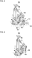
- the robot 52 may have a roll handling tool 54 for handling a label roll (see also Figure 3 ).
- the handling tool 54 can pick up and place a label roll.
- the handling tool 54 can preferably be pneumatically driven.
- the handling tool 54 can be structurally adapted to the roll holders 40, 42 so that the handling tool 54 can transfer a label roll to a respective roll holder 40, 42 as desired.
- the handling tool 54 can be adapted to a respective tensioning shaft of the roll holders 40, 42.
- the handling tool 54 is preferably designed as a roll gripper.
- the roll gripper is preferably designed as an internal gripper, e.g., a centric gripper, for gripping the respective label roll from the inside of the roll core.
- the roll gripper can optionally have a clamping device 56.
- the clamping device 56 can secure the internally gripped label roll from the outside by gently clamping it.
- the clamping device can preferably be used for label rolls that tend to telescoping and/or to secure loose tape ends.
- the handling tool 54 or the robot 52 can have at least one sensor.
- a camera 58 can be included for detecting the position of a label roll to be gripped, e.g., on the roll support 34.
- at least one distance sensor 60 can be included for detecting the distance and/or orientation of a label roll to be gripped or already gripped.
- the sensor system of the robot 52 can also be used during commissioning of the supply device 24, e.g., to determine the position of one or more components (e.g., roll support 34; roll receiving device 36, 38; roll receptacles 40, 42 and/or connectors 44, etc.). This advantageously eliminates the need for complex adjustment and calibration during commissioning.
- one or more components e.g., roll support 34; roll receiving device 36, 38; roll receptacles 40, 42 and/or connectors 44, etc.
- the robot 52 can be configured to turn a label roll using the handling tool 54.
- the label roll can thus be turned as needed so that a winding direction of the label roll corresponds to a desired winding direction for the at least one roll receiving device 36, 38.
- the robot 52 can automatically move the roll handling tool 54 (see Figure 3 ) by a tape start handling tool 62 (see Figure 4 ) and vice versa.
- the robot 52 may have an automatic tool changing system, preferably a gripper changing system, for changing between the roll handling tool 54 and the strip start handling tool 62.
- an automatic tool changing system preferably a gripper changing system
- changing between different sizes and/or designs of the same gripper type could be possible, e.g., for easy retrofitting.
- the robot 52 can change the handling tools 54 and 62 at a tool changing station 64 (see Figures 1 and 2 ).
- the tool change station 64 can be arranged within the optional protective housing 28.
- the handling tool 54 or 62 not currently being used by the robot 52 can be deposited by the robot 52 at the tool change station 64. This deposited handling tool 54 or 62 can later be picked up again by the robot 52 from the tool change station 64, in exchange for the other handling tool 54 or 62.
- the robot 52 it is also possible in principle for the robot 52 to carry both handling tools 54, 62 simultaneously, e.g., as a combination gripper (not shown in the figures).
- the tape-lead handling tool 62 shown is designed for handling a tape lead of a label roll.
- a tape lead of a label roll which is received in a roll receiving device 36, 38, can be guided to the connector 44.
- the handling tool 62 can cut a tape start of a label roll if, for example, the connector 44 does not have such functionality.
- the handling tool 62 can apply an adhesive or an adhesive tape to a tape start of a label roll if, for example, the connector 44 does not have such functionality and the robot 52 does not have an adhesive tape dispenser.
- the handling tool 62 can detect cut marks on the label tape if, for example, the connector 44 does not have an adhesive tape dispenser with such functionality.
- the handling tool 62 is preferably designed as a tape gripper.
- the handling tool 62 can have a bellows suction gripper or a clamping device for securely picking up the beginning of the tape.
- the handling tool 62 prefferably has a device for receiving and disposing of the outer tape layer unwound from the label roll.
- the robot 52 may have an adhesive tape dispenser 66 (see Figures 3 and 4 ).
- the adhesive tape dispenser 66 can be designed to dispense a preferably double-sided adhesive tape for joining label tapes.
- a tape start of a label roll which is held in a roll-holding device 36, 38, can be guided from the handling tool 62 to the adhesive tape dispenser 66 for applying the adhesive tape to the tape start.
- the adhesive tape can be applied with precise positioning, for example, by aligning the tape start based on the cut marks of the label tape detected by the cut mark sensors of the adhesive tape dispenser 66.
- the tape start thus treated can then be guided by the handling tool 62 to the connector 44, which connects the tape start to a tape end of another, used up or partially used label roll.
- the adhesive tape dispenser 66 can be the only adhesive tape dispenser of the supply device 24.
- the adhesive tape from the adhesive tape dispenser 66 can thus be used for all connectors 44 or roll receiving devices 36, 38.
- one adhesive tape dispenser can be included for each connector 44.
- testing device 68 can, for example, be a stationary testing device.
- the testing device 68 can, for example, be carried on the robot 52.
- the testing device 68 can be configured to test a label roll with respect to a winding direction, a position of a tape start, a state of a tape start (preliminary check whether the tape start can be successfully picked up (thus a time-critical disruption can be avoided later during the roll change)), a type, a diameter, a deviation from a predetermined roll parameter (e.g., label overhang over core, dimensions, weight, etc.) and/or damage.
- a predetermined roll parameter e.g., label overhang over core, dimensions, weight, etc.
- the testing device 68 may include any suitable sensor technology for testing.
- the testing device 68 may include a camera, a capacitive sensor, and/or an ultrasonic sensor.
- Inspected label rolls can then be deposited, for example, by the robot 52 onto a label roll buffer 70.
- the robot 52 can load the at least one roll receiving device 36, 38 with inspected label rolls.
- the label roll buffer 70 can be arranged within the optional protective housing 28.
- the label roll buffer 70 can be designed as a work table on which the inspected label rolls can be placed.
- the label roll buffer 70 it is also possible, for example, for the label roll buffer 70 to be merely a pallet storage location for a pallet loaded with label rolls or another storage location for at least one label roll.
- the supply device 24 can be of modular construction.
- the tape guide bridge 20 and/or 22 can be constructed from multiple bridge segment modules.
- the protective housing 28 can be constructed from multiple wall modules.
- the roll storage 34 can be designed, for example, as a pallet storage module for a lift truck and/or as a pallet storage module for an automated guided vehicle.
- the at least one roll receiving device 36, 38 can each be a module.
- the at least one label tape buffer 48, 50 can each be a module.
- the robot 52 can be a module.
- the tool changing station 64, the adhesive tape dispenser 66, the testing device 68, and/or the label roll buffer 70 can each be a module.
- each module can have its own control device.
- the control devices of the modules can be distributed accordingly within the robot cell 26.
- a preferred method for supplying the labeling device 12 may, for example, comprise one, several or all of the following method steps.
- the robot 52 can pick up a label roll from the roll storage 34 using the roll handling tool 54.
- the robot 52 can move the label roll to the inspection device 68.
- the label roll can be inspected by the inspection device 68.
- the inspection device can detect a tape start of the label roll and/or a winding direction of the label roll. If necessary, the label roll can be turned over by the robot 52 using the roll handling tool 54 if the detected winding direction does not correspond to the desired winding direction.
- the inspected and, if applicable, turned over label roll can be removed from the robot 52 by means of the roll handling tool 54 with the tape beginning preferably aligned as desired on the label roll buffer 70.
- the robot 52 can repeat the previous steps until the label roll buffer 70 is sufficiently filled.
- the robot 52 can remove an empty or partially used label roll from one of the roll holders 40, 42.
- the roll core can be disposed of.
- a partially used label roll can be placed in a separate location.
- the robot 52 can, by means of the roll handling tool 54, place a new label roll, e.g., from the label roll buffer 70, onto one of the roll holders 40, 42, preferably with a desired orientation of the tape start.
- a new label roll e.g., from the label roll buffer 70
- the robot 52 can switch from the roll handling tool 54 to the tape start handling tool 62, e.g., at the tool change station 64.
- the tape start of the label roll can be picked up by the tape start handling tool 62. If necessary, the outermost layer of label tape can be unwound from the label roll and picked up by the tape start handling tool 62.
- the picked up tape start can be fed by the robot 52 by means of the tape start handling tool 62 to the adhesive tape dispenser 66.
- the correct position for applying the adhesive strip can be determined by means of cut mark detection on the label tape, and the adhesive strip can be applied.
- the robot 52 can move the thus treated tape start to the connector 44 by means of the tape start handling tool 62.
- the label web can be cut by the connector 44 or the beginning-of-tape handling tool 62 and transferred from the beginning-of-tape handling tool 62 to the connector 44.
- the robot 52 can discard the remaining label web still on the beginning-of-tape handling tool 62.
- the robot 52 can switch from the beginning-of-tape handling tool 62 back to the roll handling tool 54, e.g., at the tool change station 64.
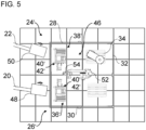
- the Figure 5 shows a modified supply device 24'.
- roller receptacles 40', 42' of the roller receptacle devices 36', 38' can be vertically aligned. More than two roller receptacles 40', 42' can also be included per roller receptacle device 36', 38'. Preferably, the roller receptacles 40', 42' are designed as drawers.
- each roll receiving device 36', 38' can have its own adhesive tape dispenser.
- the robot 52 can load one of the roll receiving devices 40', 42' with a label roll.
- the robot 52 or another device can pick up the beginning of this label roll and place it in a holding device on the roll receiving device 36', 38'.
- the adhesive tape can be applied without intervention by the robot 52 using a device on the respective roll receiving device 36', 38' and the adhesive tape dispenser.
- the bonding can again be done using a connector.
- the invention is not limited to the preferred embodiments described above. Rather, a multitude of variants and modifications are possible which also make use of the inventive concept and therefore fall within the scope of protection.
- the invention also claims protection for the subject matter and features of the subclaims, independent of the claims referred to.
- the individual features of independent claim 1 are each disclosed independently of one another.
- the features of the subclaims are also disclosed independently of all features of independent claim 1 and, for example, independently of the features relating to the presence and/or configuration of the labeling device, the labeling unit, the supply device, the robot cell, the roll storage device, the roll receiving device and/or the robot of independent claim 1. All ranges referred to herein are to be understood as disclosed in such a way that, as it were, all values falling within the respective range are individually disclosed, e.g., also as preferred, narrower outer limits of the respective range.
Landscapes
- Engineering & Computer Science (AREA)
- Robotics (AREA)
- Mechanical Engineering (AREA)
- Human Computer Interaction (AREA)
- Labeling Devices (AREA)
Applications Claiming Priority (1)
| Application Number | Priority Date | Filing Date | Title |
|---|---|---|---|
| DE102023125933.4A DE102023125933A1 (de) | 2023-09-25 | 2023-09-25 | Vorrichtung zum Etikettieren von Behältern |
Publications (1)
| Publication Number | Publication Date |
|---|---|
| EP4527751A1 true EP4527751A1 (fr) | 2025-03-26 |
Family
ID=92895424
Family Applications (1)
| Application Number | Title | Priority Date | Filing Date |
|---|---|---|---|
| EP24201866.1A Pending EP4527751A1 (fr) | 2023-09-25 | 2024-09-23 | Dispositif d'étiquetage de récipients |
Country Status (4)
| Country | Link |
|---|---|
| US (1) | US20250100738A1 (fr) |
| EP (1) | EP4527751A1 (fr) |
| CN (1) | CN119683120A (fr) |
| DE (1) | DE102023125933A1 (fr) |
Citations (4)
| Publication number | Priority date | Publication date | Assignee | Title |
|---|---|---|---|---|
| JPH0872839A (ja) * | 1994-09-07 | 1996-03-19 | K L Kk | ラベリングマシンのロールラベル自動補給装置 |
| EP1431189A1 (fr) * | 2002-12-19 | 2004-06-23 | KHS Maschinen- und Anlagenbau Aktiengesellschaft | Machine à étiqueter des récipients |
| EP3760550A1 (fr) | 2019-07-04 | 2021-01-06 | Sidel Participations | Unité de transfert de bobines de matériau d'étiquetage |
| DE102021125133A1 (de) | 2021-09-28 | 2023-03-30 | Krones Aktiengesellschaft | Mobiler Roboter und Verfahren zum Etikettenrollenwechsel an einem Etikettieraggregat |
Family Cites Families (2)
| Publication number | Priority date | Publication date | Assignee | Title |
|---|---|---|---|---|
| IT1187368B (it) * | 1985-05-10 | 1987-12-23 | Gd Spa | Sistema di alimentazione automatizzata di materiale di produzione e/o confezionamento da un magazzino a linee di lavoro |
| DE102017206549A1 (de) * | 2017-04-19 | 2018-10-25 | Robert Bosch Gmbh | Verbrauchsmaterialhandhabungsvorrichtung zu einem Transport und/oder zu einer Handhabung von zumindest einem Verbrauchsmaterial, insbesondere eines Verpackungsmaterials |
-
2023
- 2023-09-25 DE DE102023125933.4A patent/DE102023125933A1/de active Pending
-
2024
- 2024-09-23 EP EP24201866.1A patent/EP4527751A1/fr active Pending
- 2024-09-24 CN CN202411332680.7A patent/CN119683120A/zh active Pending
- 2024-09-25 US US18/895,978 patent/US20250100738A1/en active Pending
Patent Citations (4)
| Publication number | Priority date | Publication date | Assignee | Title |
|---|---|---|---|---|
| JPH0872839A (ja) * | 1994-09-07 | 1996-03-19 | K L Kk | ラベリングマシンのロールラベル自動補給装置 |
| EP1431189A1 (fr) * | 2002-12-19 | 2004-06-23 | KHS Maschinen- und Anlagenbau Aktiengesellschaft | Machine à étiqueter des récipients |
| EP3760550A1 (fr) | 2019-07-04 | 2021-01-06 | Sidel Participations | Unité de transfert de bobines de matériau d'étiquetage |
| DE102021125133A1 (de) | 2021-09-28 | 2023-03-30 | Krones Aktiengesellschaft | Mobiler Roboter und Verfahren zum Etikettenrollenwechsel an einem Etikettieraggregat |
Also Published As
| Publication number | Publication date |
|---|---|
| CN119683120A (zh) | 2025-03-25 |
| US20250100738A1 (en) | 2025-03-27 |
| DE102023125933A1 (de) | 2025-03-27 |
Similar Documents
| Publication | Publication Date | Title |
|---|---|---|
| DE4018266C2 (de) | Anlage zum Herstellen und Verpacken von Zigaretten | |
| EP3288873B1 (fr) | Procédé et dispositif d'acheminement, de fourniture et d'échange de rouleaux comportant un matériau d'emballage dans une machine d'emballage | |
| EP3288875A1 (fr) | Procédé et dispositif d'acheminement, de fourniture et d'échange de rouleaux comportant un matériau plat et/ou sous forme de film enroulé sur ces derniers | |
| EP3212552B1 (fr) | Procédé et dispositif de manipulation d'un matériau plat et/ou en feuille enroulé sur des rouleaux | |
| WO2023051969A1 (fr) | Robot mobile et procédé de changement d'un rouleau d'étiquettes sur un ensemble d'étiquetage | |
| WO2016173851A1 (fr) | Procédé et dispositif d'acheminement, de fourniture et d'échange de rouleaux comportant un matériau d'emballage dans une machine d'emballage | |
| EP1718552B1 (fr) | Dispositif de transport de rouleaux de matiere | |
| DE102015208102A1 (de) | Verfahren und Vorrichtung zur Zuförderung, Bereitstellung und zum Austausch von Rollen mit Verpackungsmaterial in einer Verpackungsmaschine | |
| EP4527752B1 (fr) | Système et procédé de préhension pour saisir un rouleau d'étiquettes | |
| EP3288876A1 (fr) | Procédé et dispositif d'acheminement, de fourniture et d'échange de rouleaux comportant un matériau d'emballage dans une machine d'emballage | |
| DE202015102191U1 (de) | Vorrichtung zur Zuförderung, Bereitstellung und zum Austausch von Rollen mit Verpackungsmaterial in einer Verpackungsmaschine | |
| EP1999057A2 (fr) | Dispositif de transport d'un ou plusieurs rouleaux de matériau comportant un système de transport et un système de logistique de rouleaux | |
| DE10109446A1 (de) | Einrichtung zur Handhabung von Bobinen | |
| EP4527751A1 (fr) | Dispositif d'étiquetage de récipients | |
| DE102022115401B3 (de) | Vorrichtung und Verfahren zum Austauschen einer Bauelement-Zuführeinrichtung an einem Bestückautomaten | |
| WO2022152407A1 (fr) | Système de préparation de commandes comprenant des contenants | |
| WO2025210069A1 (fr) | Support de rouleau d'étiquettes portatif pour appareil d'étiquetage de récipient | |
| WO2016173858A1 (fr) | Machine d'emballage et procédé d'acheminement, de fourniture et d'échange de rouleaux comportant un matériau d'emballage | |
| DE102024131999A1 (de) | Maschinenkonfiguration und Verfahren zum Lokalisieren von Formatteilen, die sich entfernt von einer Behälterbehandlungsanlage befinden | |
| DE102024102488A1 (de) | System und Verfahren zur automatisierten Deckelversorgung | |
| EP4474319A1 (fr) | Station de dépalettisation pour suremballage et système d'emballage | |
| WO2025242436A1 (fr) | Dispositif d'approvisionnement pour rouleaux de film, système, et procédé d'emballage d'empilements de palette | |
| WO2016206930A1 (fr) | Machine d'emballage et procédé pour l'acheminement, la mise à disposition et l'échange de rouleaux présentant un matériau d'emballage dans une telle machine d'emballage | |
| DE10152048A1 (de) | Einrichtung zur Versorgung von Verpackungsmaschinen mit Verpackungsmaterial |
Legal Events
| Date | Code | Title | Description |
|---|---|---|---|
| PUAI | Public reference made under article 153(3) epc to a published international application that has entered the european phase |
Free format text: ORIGINAL CODE: 0009012 |
|
| STAA | Information on the status of an ep patent application or granted ep patent |
Free format text: STATUS: THE APPLICATION HAS BEEN PUBLISHED |
|
| AK | Designated contracting states |
Kind code of ref document: A1 Designated state(s): AL AT BE BG CH CY CZ DE DK EE ES FI FR GB GR HR HU IE IS IT LI LT LU LV MC ME MK MT NL NO PL PT RO RS SE SI SK SM TR |
|
| STAA | Information on the status of an ep patent application or granted ep patent |
Free format text: STATUS: REQUEST FOR EXAMINATION WAS MADE |
|
| 17P | Request for examination filed |
Effective date: 20250926 |