EP4528036A1 - Dispositif de pivotement - Google Patents
Dispositif de pivotement Download PDFInfo
- Publication number
- EP4528036A1 EP4528036A1 EP24201319.1A EP24201319A EP4528036A1 EP 4528036 A1 EP4528036 A1 EP 4528036A1 EP 24201319 A EP24201319 A EP 24201319A EP 4528036 A1 EP4528036 A1 EP 4528036A1
- Authority
- EP
- European Patent Office
- Prior art keywords
- fastening
- pivoting
- section
- motor
- base plate
- Prior art date
- Legal status (The legal status is an assumption and is not a legal conclusion. Google has not performed a legal analysis and makes no representation as to the accuracy of the status listed.)
- Pending
Links
Images


Classifications
-
- E—FIXED CONSTRUCTIONS
- E02—HYDRAULIC ENGINEERING; FOUNDATIONS; SOIL SHIFTING
- E02F—DREDGING; SOIL-SHIFTING
- E02F3/00—Dredgers; Soil-shifting machines
- E02F3/04—Dredgers; Soil-shifting machines mechanically-driven
- E02F3/28—Dredgers; Soil-shifting machines mechanically-driven with digging tools mounted on a dipper- or bucket-arm, i.e. there is either one arm or a pair of arms, e.g. dippers, buckets
- E02F3/36—Component parts
- E02F3/3604—Devices to connect tools to arms, booms or the like
- E02F3/3677—Devices to connect tools to arms, booms or the like allowing movement, e.g. rotation or translation, of the tool around or along another axis as the movement implied by the boom or arms, e.g. for tilting buckets
-
- E—FIXED CONSTRUCTIONS
- E02—HYDRAULIC ENGINEERING; FOUNDATIONS; SOIL SHIFTING
- E02F—DREDGING; SOIL-SHIFTING
- E02F9/00—Component parts of dredgers or soil-shifting machines, not restricted to one of the kinds covered by groups E02F3/00 - E02F7/00
- E02F9/20—Drives; Control devices
- E02F9/202—Mechanical transmission, e.g. clutches, gears
Definitions
- the invention relates to a pivoting device for a work tool of a work machine, in particular an excavator or crane.
- the pivoting device comprises a first pivoting section for attaching a work tool to the pivoting device and a second pivoting section pivotable about a pivot axis relative to the first pivoting section for attaching the pivoting device to a boom arm of the work machine.
- Such a pivoting device is generally known and is typically used to pivot the work tool attached to the extension arm by means of the pivoting device.
- the pivoting device is generally mounted on the extension arm in such a way that the pivot axis of the pivoting device is aligned approximately parallel to the longitudinal extension of the extension arm.
- a different orientation of the pivot axis relative to the extension arm is also possible.
- the swivel device can be used alone or in conjunction with a rotating device to rotate the work tool, particularly by 360°.
- the rotation axis of the rotating device is preferably aligned perpendicular to the pivot axis of the swivel device.
- the combination of the swivel device and the rotating device increases the number of degrees of freedom in which the work tool can be moved, thus enabling work in hard-to-reach places and/or around obstacles.
- the swivel device For such demanding applications, it is desirable for the swivel device to have a particularly compact design and at the same time allow swiveling within the largest possible swivel range.
- a pivoting device having the features of claim 1 and in particular by a drive which is spatially arranged between the first pivoting section and the second pivoting section and which is designed to pivot the first pivoting section relative to the second pivoting section about the pivot axis.
- the invention is based on the idea of integrating a drive of a swivel device in the manner of a hub drive into the swivel device.
- the swivel device like the hub drive, thereby has a particularly compact design.
- the swivel device has a comparatively large swivel range, which is ultimately only limited by the structural conditions of the swivel device.
- the swivel device according to the invention enables swiveling from a non-swivelled neutral position by 90° in opposite directions, resulting in a total swivel range of 180°. In principle, however, a larger swivel range of more than 180° is also possible depending on the structural properties of the swivel device.
- the first pivoting section and the second pivoting section of the pivoting device each comprise a base plate.
- the drive is thus located between the base plates of the two pivoting sections, which can be pivoted relative to each other.
- the base plates enable a good connection of the pivoting device to the extension arm of the work device and to the work tool.
- the base plates can be flat and each define a plane, with the intersection angle between the planes changing by pivoting the pivoting sections of the pivoting device. In the non-pivoted neutral position, the planes are aligned parallel to each other.
- a quick-change unit can be arranged on the base plate of the first swivel section and/or on the base plate of the second swivel section.
- the quick-change units are arranged on the side of the respective base plate facing away from the drive. This facilitates optional use of the swivel device.
- the quick-change unit of the first pivoting section which serves for coupling to the work tool, is complementary to a quick-change unit provided on the work tool.
- the quick-change unit of the first pivoting section can be the same as a quick-change unit typically provided on the extension arm for coupling to the work tool.
- the quick-change unit of the first pivoting section can have claws designed to receive a quick-change frame provided on the work tool.
- the quick-change unit of the second pivoting section used for coupling to the extension arm can be complementary to a quick-change unit formed on the extension arm.
- the quick-change unit of the second pivoting section can be modeled on the quick-change unit of the work tool.
- the quick-change unit of the second pivoting section can comprise a quick-change frame designed to be received in claws provided for this purpose on the extension arm.
- a rotating device with a rotary drive defining a rotation axis can also be provided on one of the base plates.
- the rotating device is arranged on the side of the base plate facing away from the drive.
- the rotational axis of the rotary drive which can also be referred to as a rotator, is aligned at least approximately perpendicular to the pivot axis of the pivoting device.
- This allows the working tool to be pivoted not only about the pivot axis, but also about the rotational axis of the rotary drive, which is aligned at least approximately perpendicular to it. This enables a more versatile use of the working tool.
- the drive may comprise a motor.
- the motor comprises a rotor rotatable about a rotational axis, which provides the rotational movement necessary for pivoting the pivoting device.
- the motor is bidirectionally operable, allowing pivoting in two opposite directions.
- a particularly compact design of the swivel device is achieved when the rotor's rotational axis is aligned parallel to the swivel axis of the swivel device, especially when the rotational axis and the swivel axis are aligned coaxially with each other.
- a compact design of the swivel device is also possible when the rotor's rotational axis is parallel to the swivel axis of the swivel device.
- the motor and/or rotary drive of the rotating device can be hydraulically driven. This allows a hydraulic system already present for operating the boom and/or the work tool to be used to drive the motor or rotary drive.
- the motor or rotary drive can, for example, be designed as a so-called “internally” actuated hydraulic radial piston motor, in which a stator is arranged essentially radially within the rotor.
- a stator is arranged essentially radially within the rotor.
- Such a motor is generally known and comprises several drive pistons displaceable by hydraulic fluid, each guided in radial bores provided for this purpose in the stator.
- the radial bores are arranged in a star shape with respect to the rotational axis, so that the rotor is rotated by alternating, sequential displacement of the drive pistons.
- radial piston motor with internal thrust another motor can also be used.
- a hydraulic radial piston motor with external thrust can be used.
- the drive pistons are guided in a stator arranged radially outward relative to the rotor.
- the motor or rotary drive can also be designed as a hydraulic axial piston motor.
- the drive pistons are not displaced radially, but rather parallel to the axis of rotation.
- the motor or rotary drive can also be driven electrically, for example in the form of an electric motor.
- the drive may comprise a gear which can be driven by the motor.
- the pivoting device has a particularly compact design if the motor and the gearbox are arranged in series, as seen in the direction of the pivot axis.
- the motor can be attached to the gearbox, for example, to a gearbox housing.
- the motor can be mounted exclusively on the gearbox.
- the motor is thus supported solely by the gearbox and not by any other component of the swivel device.
- This design allows for an even simpler and more compact design of the swivel device.
- the pivoting device can have a fastening device for fastening the pivoting device to the extension arm of the work machine, wherein the fastening device is designed such that the motor and/or the connections for driving the motor face the work machine when the pivoting device is fastened to the work machine.
- the fastening device is designed such that the motor and/or the connections for driving the motor face the work machine when the pivoting device is fastened to the work machine.
- the fastening device can, for example, be the quick-change unit mentioned above.
- the fastening device can also be formed by means by which the swivel device can be attached directly to the boom arm of the work machine, for example, by a screw connection.
- the transmission can comprise a first transmission part and a second transmission part rotatable about a transmission axis relative to the first transmission part, wherein the first transmission part is attached to the first pivoting section of the pivoting device and the second transmission part is attached to the second pivoting section of the pivoting device.
- the transmission axis like the rotational axis of the rotor, can be aligned parallel, in particular coaxially or spaced parallel, to the pivoting axis of the pivoting device.
- the first gear part is fastened to a first fastening section protruding from the base plate of the first pivoting section and/or the second gear part is fastened to a second fastening section protruding from the base plate of the second pivoting section.
- additional sections can also protrude from the base plates, for example to provide additional support for the drive and/or to accommodate a pivot bearing.
- the first fastening section can have a fastening surface which is aligned at least approximately at right angles to the base plate of the first pivoting section and to which the first gear part is fastened.
- the second fastening section can have a fastening surface which is aligned at least approximately at right angles to the base plate of the second pivoting section and to which the second gear part is fastened.
- At least one of the gear parts of the gearbox and/or the motor, in particular the motor attached to one of the gear parts, can be accommodated at least in sections in a fastening sleeve.
- the first gear part can be attached to the base plate of the first pivoting section by means of a first fastening sleeve that accommodates the first gear part at least in sections.
- the first fastening section is formed by the first fastening sleeve.
- the second gear part can be attached to the base plate of the second pivoting section by means of a second fastening sleeve that accommodates the second gear part at least in sections.
- the second fastening section is preferably formed by the second fastening sleeve.
- the first fastening sleeve can have a first flat contact surface via which the first fastening sleeve is fastened to the base plate of the first pivoting section.
- the second fastening sleeve may have a second flat contact surface via which the second fastening sleeve is fastened to the base plate of the second pivoting section.
- the first fastening sleeve can comprise a fastening surface, as described above, oriented at least approximately perpendicular to the base plate of the first pivoting section, to which the first gear part is fastened.
- the second fastening sleeve can comprise a fastening surface, as described above, oriented at least approximately perpendicular to the base plate of the second pivoting section, to which the second gear part is fastened.
- the first fastening sleeve has, on its side facing away from its fastening surface, a beveled end face that is inclined from the first contact surface toward the fastening surface of the first fastening sleeve.
- the first contact surface thus forms a long side of the first fastening sleeve.
- the second fastening sleeve may have a beveled end face on its side facing away from its fastening surface, which is inclined from the second contact surface toward the fastening surface of the second fastening sleeve. Accordingly, the second contact surface forms a long side of the second fastening sleeve.
- the beveled end faces of the mounting sleeves allow for material and weight savings compared to a non-beveled mounting sleeve.
- the contact surfaces forming the long sides of the mounting sleeve enable secure attachment of the respective mounting sleeve to the corresponding base plate.
- a compact design of the swivel device is achieved if the swivel axis of the swivel device and the longitudinal center axis of the first fastening sleeve are aligned at least approximately parallel, in particular coaxial, to one another.
- the pivot axis of the pivoting device and the longitudinal center axis of the second fastening sleeve can be aligned at least approximately parallel, in particular coaxial, to one another.
- the first fastening sleeve and the second fastening sleeve can have at least approximately identical basic shapes. This makes it possible to use identical base bodies for the respective fastening sleeves, which may then need to be adapted to the respective conditions of the first transmission part or the second transmission part and/or the engine.
- the drive includes a brake.
- the brake can be assigned either to the transmission or to the motor.
- the brake can be assigned to both the transmission and the motor.
- the brake is preferably designed such that it is active and braking when the motor is not driven. This eliminates the need for the motor to be active to maintain a desired swivel position. Rather, the swivel mechanism remains in the desired swivel position even when the motor is inactive.
- the brake is therefore preferably only active and braking when the motor is not driven, thus serving as a parking brake.
- the brake can be a multi-disk brake.
- Multi-disk brakes are generally known for their high braking torque and are therefore particularly suitable for locking the swivel device in a desired Swivel position.
- other types of brakes can also be used for the same purpose, such as drum brakes, disc brakes, or the like.
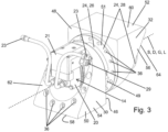
- FIG. 1 and 2 a first embodiment of a pivoting device
- Fig. 3 and 4 A second embodiment of a pivoting device. The similarities between the two embodiments are described below, with the differences between the embodiments being discussed at some point.
- the pivoting devices shown in the drawings each comprise a first pivoting section 10 for fastening a work tool to the pivoting device and a second pivoting section 12 pivotable about a pivot axis S relative to the first pivoting section 10 for fastening the swivel device on a boom of a work machine, such as an excavator or a crane.
- the two pivoting sections 10, 12 each comprise a base plate 16, 18.
- the base plates 16, 18 are flat, with the base plate 16 of the first pivoting section 10 defining a first plane E 1 and the base plate 18 of the second pivoting section 12 defining a second plane E 2 ( Fig. 2 and 4 ).
- the base plates 16, 18 are Fig. 3 not shown.
- the pivoting device comprises a drive 14, which is arranged spatially between the two pivotable pivot sections 10, 12 in the manner of a hub drive. More precisely, the drive 14 is arranged between the base plate 16 of the first pivot section 10 and the base plate 18 of the second pivot section 12, with the base plates 16, 18 surrounding the drive 14 in the radial direction with respect to the pivot axis S.
- a quick-change unit (not shown in the drawings) can be provided on the side of the base plate 16 of the first swivel section 10 facing away from the drive 14 or on the side of the base plate 18 of the second swivel section 12 facing away from the drive 14.
- the quick-change unit formed on the first pivot section 10 serves to attach the work tool to the pivoting device.
- the quick-change unit of the first pivot section 10 can be designed to complement a quick-change unit formed on the work tool.
- the quick-change unit of the first pivot section 10 can have claws that serve to receive a quick-change frame provided on the work tool.
- the quick-change unit formed on the second pivoting section 12 can be designed to complement a quick-change unit provided on the extension arm.
- the quick-change unit of the second pivoting section 12 can be designed similarly to the quick-change frame of the work tool and can be received in claws provided for attachment to the extension arm.
- the second quick-change unit thus forms a fastening device for attaching the pivoting device to the extension arm of the work machine.
- a rotating device can be provided between at least one of the base plates 16, 18 and the respective quick-change unit to enable a 360° rotation of the working tool and/or the pivoting direction about a rotation axis oriented perpendicular to the pivot axis S. Such a configuration with a rotating device is not shown in the drawings.
- At least one of the base plates 16, 18 can be provided with at least one bore (not shown in the drawings) via which a hydraulic connection to the rotating device and/or the hydraulic attachment can be established.
- the drive 14 comprises a motor 20, which in the illustrated embodiments is designed as a hydraulically driven motor. However, the motor can also be designed as an electrically driven motor.
- a hydraulic connection block 21 with hydraulic connections 23 is provided on the motor 20. Furthermore, a check valve 29 is provided on the hydraulic connection block 21 ( Fig. 3 and 4 ).
- the second quick-change unit is preferably designed such that the motor 20 and/or its connections 23 face the working machine when the swivel device is attached to the working machine.
- the motor 20 comprises a rotor 22 rotatable about a rotation axis D, which Fig. 2 is only shown schematically and which provides a rotary movement for a gear 24 of the drive 14.
- the motor 20 and the gear 24 are arranged in series in the direction of the pivot axis S for a compact construction of the pivoting device, wherein the motor 20 is connected to the gear 24 to drive the gear 24.
- the drive 14 comprises a brake, not further shown in the drawings, which can be designed in the form of a multi-disk brake and which is conveniently integrated into the gear 24 for a compact design of the swivel device.
- the brake is designed in such a way that it is only active when the motor 20 is not driven, ie when the motor 20 is inactive.
- the brake serves thus acting as a parking brake. This allows the desired swivel position of the swivel device to be maintained even when motor 20 is inactive.
- the drive 14 is attached via the gear 24 to the mutually pivotable pivot sections 10, 12 of the pivoting device, namely by attaching a first part 26 of the gear 24 to the first pivot section 10 of the pivoting device and a second part 28 of the gear 24, which is rotatable relative to the first gear part 26, to the second pivot section 12 of the pivoting device. More precisely, the first gear part 26 is attached to a fastening section 30 protruding from the base plate 16 of the first pivot section 10, and the second gear part 28 is attached to a fastening section 32 protruding from the base plate 18 of the second pivot section 12 via a screw connection using a plurality of screws 36 ( Fig. 2 and 3 ).
- first gear part 26 is fastened to the fastening section 30 on a fastening surface 46 which is aligned at least approximately at right angles to the base plate 16 of the first pivoting section 10.
- the first gear part 26 in the present embodiments has a flange 49 which lies flat against the first fastening surface 46 and which is connected to the fastening section 30 via the aforementioned screw connection.
- the second gear part 28 is attached to the second attachment portion 32 on a mounting surface 48 aligned at least approximately at right angles to the base plate 18 of the second pivot portion 12.
- the second gear part 28 also has a flange 51 that lies flat against the second mounting surface 48 and is connected to the mounting portion 32 via the aforementioned screw connection.
- the fastening surfaces 46, 48 face each other.
- the fastening section 32 of the second pivoting section 12 of the pivoting device has a passage 44 (see e.g. Fig. 2 ). This makes it possible to connect the motor 20 to the gearbox 24.
- the fastening sections 30, 32 are plate-shaped.
- the fastening sections 30, 32 each have a flat side on their radial outer circumference with respect to the pivot axis S.
- the fastening sections 30, 32 are each fastened to the corresponding base plate 16, 18 via the flat side.
- On an outer side facing away from the flat side, the fastening sections 30, 32 are rounded, so that the fastening sections 30, 32 have an overall D-shaped or U-shaped outer contour when viewed in the direction of the pivot axis S.
- the second part 28 of the gear 24 in the pivoting device of the first embodiment is fastened at one axial end of the pivoting device to a support section 34 projecting from the base plate 18 of the second pivoting section 12.
- the second gear part 28 is thus held between the fastening section 32 and the support section 34 of the second pivoting section 12 ( Fig. 2 ).
- the first fastening section 30 has a passage 33 for the second gear part 28 for this purpose.
- the gear 24 is radially surrounded by a cylindrical protective cover 25 to protect it against damage and contamination, which is particularly clearly visible in Fig. 2 can be seen.
- a further protective cover can be provided between the fastening section 30 of the first pivot section 10 and the fastening section 32 of the second pivot section 12.
- the fastening sections 30, 32 are arranged approximately centrally between the axial ends of the pivoting device, as viewed in the direction of the pivot axis S. Furthermore, the first fastening section 30 is arranged between the second fastening section 32 and the support section 34, as viewed in the direction of the pivot axis S.
- a pivot bearing 38 is provided at an axial end of the pivoting device of the first embodiment facing away from the support section 34, which is arranged between a first bearing section 40 projecting at right angles from the base plate 16 of the first pivoting section 10 and a second bearing section 42 projecting at right angles from the base plate of the second pivoting section 12.
- pivoting device may comprise further pivot bearings in addition to the pivot bearing 38 described here, particularly in the case of larger dimensioned pivoting devices.
- the pivot axis S runs centrally through the pivot bearing 38, so that the pivot axis S of the pivot device and the rotation axis of the pivot bearing 38 are coaxially aligned with each other.
- the first fastening section 30 and the second fastening section 32 are not plate-shaped as in the first embodiment, but are each formed by a fastening sleeve 50, 52.
- Each of the fastening sleeves 50, 52 has a passage extending in the axial direction with respect to its longitudinal center axis L, in which one of the gear parts 26, 28 is accommodated in sections and which is surrounded by a wall 54, 56 in the radial direction. Due to the perspective view, Fig. 3 only the passage extending through the first fastening sleeve 50 can be seen.
- the gear parts 26, 28 are received in the respective passages of the mounting sleeves 50, 52 such that the longitudinal center axis L of the mounting sleeves and the gear axis G of the gear 24, as well as the pivot axis S of the pivoting device, are coaxially aligned with one another in the assembled state of the pivoting device. Understandably, in this embodiment, the rotational axis D of the motor 20 is also coaxially aligned with the pivot axis S of the pivoting device.
- the fastening sleeves 50, 52 For fastening the gear parts 26, 28 to the respective fastening sleeves 50, 52, the fastening sleeves 50, 52, as well as the plate-like fastening sections 30, 32 of the first embodiment, each have a fastening surface 46, 48 aligned at least approximately at right angles to the corresponding base plates 16, 18.
- the gear parts are fastened to the fastening surfaces 46, 48.
- 26, 28 are each fastened as described above via their flanges 49, 51 by means of screws 36.
- the screws 36 are each received in the fastening sleeves 50, 52 in bores which penetrate the respective wall 54, 56 of the fastening sleeves 50, 52 in the axial direction with respect to the longitudinal center axis L of the fastening sleeves 50, 52 and which surround the passage formed in the fastening sleeves 54, 56 in the radial direction.
- first fastening sleeve 50 is fastened to the base plate 16 of the first pivoting section 10 via a first planar contact surface 58 and the second fastening sleeve 52 is fastened to the base plate 18 of the second pivoting section 12 via a second planar contact surface 60 ( Fig. 3 combined with Fig. 4 ).
- the fastening sleeves 50, 52 are rounded, so that the fastening sleeves 50, 52 have a D-like or U-like cross-sectional shape similar to the plate-like fastening sections 30, 32 of the first embodiment.
- each of the fastening sleeves 50, 52 has, on its side facing away from its fastening surface 46, 48, a beveled end face 62, 64, which is inclined from the contact surface 58, 60 of the respective fastening sleeve 50, 52 in the direction of its respective fastening surface 46, 48.
- the contact surfaces 58, 60 thus each form a long side of the fastening sleeves 50, 52.
- the beveled end faces 62, 64 of the mounting sleeves 50, 52 allow for material and weight savings compared to a non-beveled mounting sleeve.
- the contact surfaces 58, 60 provide a sufficiently large area to securely attach the mounting sleeves 50, 52 to the respective base plates 16, 18 of the pivot sections 10, 12.
- gear components 26, 28 of the gearbox 24 and the motor 20 connected to the gearbox 24 are only partially accommodated in the mounting sleeves 50, 52 by the beveled end faces 62, 64. This facilitates access to the gear components 26, 28 and the motor 20 for maintenance purposes. At the same time, the remaining components of the drive 24 are protected from contamination and/or damage by the mounting sleeves 50, 52.
- each of the fastening sleeves 50, 52 has a trapezoidal, in particular essentially rectangular trapezoidal, contour due to its oblique end faces 62, 64 in a projection onto a longitudinal sectional plane extending through the longitudinal center axis L and the corresponding contact surface 58, 60.
- the fastening sleeves can also have an essentially triangular contour.
- first fastening sleeve 50 and the second fastening sleeve 52 also have at least approximately identical basic shapes.
- the fastening sleeves 50, 52 can thus be prefabricated with identical dimensions and then only need to be adapted, if necessary, to the specific conditions of the drive 24, such as appropriate recesses for the motor connections 23.
- one of the gear parts 26, 28 may be attached to the base plate 16, 18 in a manner as described in connection with the first embodiment, and the corresponding other gear part 28, 26 may be attached to the other base plate 18, 16 in a manner as described in connection with the second embodiment.
- the rotational axis D of the rotor 22 and the gear axis G of the gear 24 are aligned coaxially with the pivot axis S of the pivoting device, whereby the pivoting device has a particularly compact design.
- the first pivoting section 10 can be pivoted relative to the second pivoting section 12 of the pivoting device by at least 90° in opposite directions relative to the neutral position, as shown, for example, by Fig. 1 This results in a swivel range of at least 180° for the swivel device.
Landscapes
- Engineering & Computer Science (AREA)
- Mechanical Engineering (AREA)
- Mining & Mineral Resources (AREA)
- Civil Engineering (AREA)
- General Engineering & Computer Science (AREA)
- Structural Engineering (AREA)
- Jib Cranes (AREA)
- Connection Of Motors, Electrical Generators, Mechanical Devices, And The Like (AREA)
Applications Claiming Priority (1)
| Application Number | Priority Date | Filing Date | Title |
|---|---|---|---|
| DE202023105526.5U DE202023105526U1 (de) | 2023-09-22 | 2023-09-22 | Schwenkvorrichtung |
Publications (1)
| Publication Number | Publication Date |
|---|---|
| EP4528036A1 true EP4528036A1 (fr) | 2025-03-26 |
Family
ID=92882588
Family Applications (1)
| Application Number | Title | Priority Date | Filing Date |
|---|---|---|---|
| EP24201319.1A Pending EP4528036A1 (fr) | 2023-09-22 | 2024-09-19 | Dispositif de pivotement |
Country Status (2)
| Country | Link |
|---|---|
| EP (1) | EP4528036A1 (fr) |
| DE (1) | DE202023105526U1 (fr) |
Citations (3)
| Publication number | Priority date | Publication date | Assignee | Title |
|---|---|---|---|---|
| US20100095720A1 (en) * | 2007-03-15 | 2010-04-22 | Viewquest Pty Ltd | Locking devices |
| US20110147032A1 (en) * | 2009-11-25 | 2011-06-23 | Weyer Dean R | Tiltable tool assembly |
| EP3719210A1 (fr) * | 2019-04-04 | 2020-10-07 | Rädlinger Maschinen- und Stahlbau GmbH | Combinaison de moteur oscillant et de changement rapide |
Family Cites Families (5)
| Publication number | Priority date | Publication date | Assignee | Title |
|---|---|---|---|---|
| DE9203925U1 (de) * | 1991-09-27 | 1992-07-02 | Lewin, Heinz-Ulrich, 4600 Dortmund | Anbauteil für Bagger mit Schwenkmotor |
| ATE184947T1 (de) * | 1995-02-18 | 1999-10-15 | Thumm Heinz Oelhydraulik | Drehvorrichtung für baggergreifer |
| DE10115526A1 (de) * | 2001-03-28 | 2002-10-24 | Hermann Korte Vertriebs Gmbh | Schwenkrotator |
| DE20214615U1 (de) * | 2002-09-20 | 2003-03-06 | IMO-Industrie-Antriebseinheit Stoll & Russ GmbH, 91350 Gremsdorf | Schwenktrieb |
| DE102020106958A1 (de) * | 2020-03-13 | 2021-09-16 | Liebherr-Components Biberach Gmbh | Antriebseinheit sowie Bau- und/oder Materialumschlagsmaschine mit einer solchen Antriebseinheit |
-
2023
- 2023-09-22 DE DE202023105526.5U patent/DE202023105526U1/de active Active
-
2024
- 2024-09-19 EP EP24201319.1A patent/EP4528036A1/fr active Pending
Patent Citations (3)
| Publication number | Priority date | Publication date | Assignee | Title |
|---|---|---|---|---|
| US20100095720A1 (en) * | 2007-03-15 | 2010-04-22 | Viewquest Pty Ltd | Locking devices |
| US20110147032A1 (en) * | 2009-11-25 | 2011-06-23 | Weyer Dean R | Tiltable tool assembly |
| EP3719210A1 (fr) * | 2019-04-04 | 2020-10-07 | Rädlinger Maschinen- und Stahlbau GmbH | Combinaison de moteur oscillant et de changement rapide |
Also Published As
| Publication number | Publication date |
|---|---|
| DE202023105526U1 (de) | 2025-01-08 |
Similar Documents
| Publication | Publication Date | Title |
|---|---|---|
| DE3342305C2 (fr) | ||
| EP2561145B1 (fr) | Dispositif de rotation pour un équipement auxiliaire d'un engin de travaux publics | |
| DE102008041982A1 (de) | Anbaufrässystem mit Schneidköpfen und Fräskette | |
| EP2138272A2 (fr) | Outil de dévissage d'un piston sur la tige de piston d'un cylindre hydraulique et cylindre hydraulique | |
| DE10296905T5 (de) | Planetenradgetriebeeinheit | |
| DE102013205935B3 (de) | Ankuppeleinrichtung für ein Baggeranbaugerät | |
| DE2361022C2 (de) | Schwenkantrieb für einen auf einem Fahrgestell angeordneten Baggeraufbau | |
| EP3683362B1 (fr) | Fraise pour parois moulées | |
| EP4263407B1 (fr) | Support d'enrouleur de câble pour supporter en rotation un enrouleur de câble | |
| EP4528036A1 (fr) | Dispositif de pivotement | |
| DE102022125550A1 (de) | System zur drehmomentübertragung von antriebswellen auf fräswalzen | |
| EP3760902B1 (fr) | Fixation d'armature pour raccords de tuyaux hydrauliques, machine de construction et procédé | |
| EP4502278A1 (fr) | Système de changement rapide | |
| DE1634950B2 (de) | Baggergreifer | |
| EP4311881A1 (fr) | Roue de fraisage pour une fraise pour rideaux souterrains et procédé de transformation d'une roue de fraisage | |
| EP2024144A1 (fr) | Dispositif d'entraînement de main de robot | |
| DE69004273T2 (de) | Vorrichtung zum Befestigen von Frästrommeln an einem Baggergerät,das für das Ausheben von Gräben im Boden bestimmt ist. | |
| DE2424645C3 (de) | Ausleger für eine Streckenvortriebsmaschine | |
| EP3341172A1 (fr) | Dispositif d'enlèvement de matériau de construction | |
| DE102019133396A1 (de) | Gelenkantrieb mit Planetengetriebe, Großmanipulator und Autobetonpumpe | |
| EP3093101B1 (fr) | Système de changement destiné a la reception d'un dispositif d'application destiné a être utilisé dans une ligne de montage de véhicules automobiles | |
| EP4686787A1 (fr) | Fraise pour parois moulées avec un outil de coupe réglable | |
| DE102011079492A1 (de) | Antriebsvorrichtung für ein Flurförderzeug | |
| DE202023104325U1 (de) | Schnellwechselsystem | |
| EP4711525A1 (fr) | Dispositif de changement rapide |
Legal Events
| Date | Code | Title | Description |
|---|---|---|---|
| PUAI | Public reference made under article 153(3) epc to a published international application that has entered the european phase |
Free format text: ORIGINAL CODE: 0009012 |
|
| STAA | Information on the status of an ep patent application or granted ep patent |
Free format text: STATUS: THE APPLICATION HAS BEEN PUBLISHED |
|
| AK | Designated contracting states |
Kind code of ref document: A1 Designated state(s): AL AT BE BG CH CY CZ DE DK EE ES FI FR GB GR HR HU IE IS IT LI LT LU LV MC ME MK MT NL NO PL PT RO RS SE SI SK SM TR |
|
| STAA | Information on the status of an ep patent application or granted ep patent |
Free format text: STATUS: REQUEST FOR EXAMINATION WAS MADE |
|
| 17P | Request for examination filed |
Effective date: 20250908 |