EP4528287A2 - Systèmes et procédés de coloration d'échantillons biologiques - Google Patents
Systèmes et procédés de coloration d'échantillons biologiques Download PDFInfo
- Publication number
- EP4528287A2 EP4528287A2 EP24213921.0A EP24213921A EP4528287A2 EP 4528287 A2 EP4528287 A2 EP 4528287A2 EP 24213921 A EP24213921 A EP 24213921A EP 4528287 A2 EP4528287 A2 EP 4528287A2
- Authority
- EP
- European Patent Office
- Prior art keywords
- sample
- fluid
- reagent
- substrate
- applicator
- Prior art date
- Legal status (The legal status is an assumption and is not a legal conclusion. Google has not performed a legal analysis and makes no representation as to the accuracy of the status listed.)
- Pending
Links
Images





Classifications
-
- G—PHYSICS
- G01—MEASURING; TESTING
- G01N—INVESTIGATING OR ANALYSING MATERIALS BY DETERMINING THEIR CHEMICAL OR PHYSICAL PROPERTIES
- G01N35/00—Automatic analysis not limited to methods or materials provided for in any single one of groups G01N1/00 - G01N33/00; Handling materials therefor
- G01N35/10—Devices for transferring samples or any liquids to, in, or from, the analysis apparatus, e.g. suction devices, injection devices
- G01N35/1009—Characterised by arrangements for controlling the aspiration or dispense of liquids
- G01N35/1016—Control of the volume dispensed or introduced
-
- B—PERFORMING OPERATIONS; TRANSPORTING
- B01—PHYSICAL OR CHEMICAL PROCESSES OR APPARATUS IN GENERAL
- B01L—CHEMICAL OR PHYSICAL LABORATORY APPARATUS FOR GENERAL USE
- B01L3/00—Containers or dishes for laboratory use, e.g. laboratory glassware; Droppers
- B01L3/02—Burettes; Pipettes
- B01L3/0241—Drop counters; Drop formers
- B01L3/0268—Drop counters; Drop formers using pulse dispensing or spraying, eg. inkjet type, piezo actuated ejection of droplets from capillaries
-
- B—PERFORMING OPERATIONS; TRANSPORTING
- B01—PHYSICAL OR CHEMICAL PROCESSES OR APPARATUS IN GENERAL
- B01L—CHEMICAL OR PHYSICAL LABORATORY APPARATUS FOR GENERAL USE
- B01L3/00—Containers or dishes for laboratory use, e.g. laboratory glassware; Droppers
- B01L3/50—Containers for the purpose of retaining a material to be analysed, e.g. test tubes
- B01L3/502—Containers for the purpose of retaining a material to be analysed, e.g. test tubes with fluid transport, e.g. in multi-compartment structures
- B01L3/5027—Containers for the purpose of retaining a material to be analysed, e.g. test tubes with fluid transport, e.g. in multi-compartment structures by integrated microfluidic structures, i.e. dimensions of channels and chambers are such that surface tension forces are important, e.g. lab-on-a-chip
-
- B—PERFORMING OPERATIONS; TRANSPORTING
- B01—PHYSICAL OR CHEMICAL PROCESSES OR APPARATUS IN GENERAL
- B01L—CHEMICAL OR PHYSICAL LABORATORY APPARATUS FOR GENERAL USE
- B01L9/00—Supporting devices; Holding devices
- B01L9/52—Supports specially adapted for flat sample carriers, e.g. for plates, slides, chips
-
- G—PHYSICS
- G01—MEASURING; TESTING
- G01N—INVESTIGATING OR ANALYSING MATERIALS BY DETERMINING THEIR CHEMICAL OR PHYSICAL PROPERTIES
- G01N1/00—Sampling; Preparing specimens for investigation
- G01N1/28—Preparing specimens for investigation including physical details of (bio-)chemical methods covered elsewhere, e.g. G01N33/50, C12Q
- G01N1/30—Staining; Impregnating ; Fixation; Dehydration; Multistep processes for preparing samples of tissue, cell or nucleic acid material and the like for analysis
- G01N1/31—Apparatus therefor
- G01N1/312—Apparatus therefor for samples mounted on planar substrates
-
- G—PHYSICS
- G01—MEASURING; TESTING
- G01N—INVESTIGATING OR ANALYSING MATERIALS BY DETERMINING THEIR CHEMICAL OR PHYSICAL PROPERTIES
- G01N35/00—Automatic analysis not limited to methods or materials provided for in any single one of groups G01N1/00 - G01N33/00; Handling materials therefor
- G01N35/10—Devices for transferring samples or any liquids to, in, or from, the analysis apparatus, e.g. suction devices, injection devices
- G01N35/1002—Reagent dispensers
-
- G—PHYSICS
- G01—MEASURING; TESTING
- G01N—INVESTIGATING OR ANALYSING MATERIALS BY DETERMINING THEIR CHEMICAL OR PHYSICAL PROPERTIES
- G01N35/00—Automatic analysis not limited to methods or materials provided for in any single one of groups G01N1/00 - G01N33/00; Handling materials therefor
- G01N35/10—Devices for transferring samples or any liquids to, in, or from, the analysis apparatus, e.g. suction devices, injection devices
- G01N35/1009—Characterised by arrangements for controlling the aspiration or dispense of liquids
-
- G—PHYSICS
- G01—MEASURING; TESTING
- G01N—INVESTIGATING OR ANALYSING MATERIALS BY DETERMINING THEIR CHEMICAL OR PHYSICAL PROPERTIES
- G01N35/00—Automatic analysis not limited to methods or materials provided for in any single one of groups G01N1/00 - G01N33/00; Handling materials therefor
- G01N35/10—Devices for transferring samples or any liquids to, in, or from, the analysis apparatus, e.g. suction devices, injection devices
- G01N35/1009—Characterised by arrangements for controlling the aspiration or dispense of liquids
- G01N35/1011—Control of the position or alignment of the transfer device
-
- B—PERFORMING OPERATIONS; TRANSPORTING
- B01—PHYSICAL OR CHEMICAL PROCESSES OR APPARATUS IN GENERAL
- B01L—CHEMICAL OR PHYSICAL LABORATORY APPARATUS FOR GENERAL USE
- B01L2200/00—Solutions for specific problems relating to chemical or physical laboratory apparatus
- B01L2200/16—Reagents, handling or storing thereof
-
- B—PERFORMING OPERATIONS; TRANSPORTING
- B01—PHYSICAL OR CHEMICAL PROCESSES OR APPARATUS IN GENERAL
- B01L—CHEMICAL OR PHYSICAL LABORATORY APPARATUS FOR GENERAL USE
- B01L2300/00—Additional constructional details
- B01L2300/18—Means for temperature control
- B01L2300/1805—Conductive heating, heat from thermostatted solids is conducted to receptacles, e.g. heating plates, blocks
-
- B—PERFORMING OPERATIONS; TRANSPORTING
- B01—PHYSICAL OR CHEMICAL PROCESSES OR APPARATUS IN GENERAL
- B01L—CHEMICAL OR PHYSICAL LABORATORY APPARATUS FOR GENERAL USE
- B01L2300/00—Additional constructional details
- B01L2300/18—Means for temperature control
- B01L2300/1805—Conductive heating, heat from thermostatted solids is conducted to receptacles, e.g. heating plates, blocks
- B01L2300/1822—Conductive heating, heat from thermostatted solids is conducted to receptacles, e.g. heating plates, blocks using Peltier elements
-
- B—PERFORMING OPERATIONS; TRANSPORTING
- B01—PHYSICAL OR CHEMICAL PROCESSES OR APPARATUS IN GENERAL
- B01L—CHEMICAL OR PHYSICAL LABORATORY APPARATUS FOR GENERAL USE
- B01L2400/00—Moving or stopping fluids
- B01L2400/04—Moving fluids with specific forces or mechanical means
- B01L2400/0403—Moving fluids with specific forces or mechanical means specific forces
- B01L2400/0433—Moving fluids with specific forces or mechanical means specific forces vibrational forces
- B01L2400/0439—Moving fluids with specific forces or mechanical means specific forces vibrational forces ultrasonic vibrations, vibrating piezo elements
-
- G—PHYSICS
- G01—MEASURING; TESTING
- G01N—INVESTIGATING OR ANALYSING MATERIALS BY DETERMINING THEIR CHEMICAL OR PHYSICAL PROPERTIES
- G01N1/00—Sampling; Preparing specimens for investigation
- G01N1/28—Preparing specimens for investigation including physical details of (bio-)chemical methods covered elsewhere, e.g. G01N33/50, C12Q
- G01N1/30—Staining; Impregnating ; Fixation; Dehydration; Multistep processes for preparing samples of tissue, cell or nucleic acid material and the like for analysis
- G01N1/31—Apparatus therefor
- G01N2001/317—Apparatus therefor spraying liquids onto surfaces
-
- G—PHYSICS
- G01—MEASURING; TESTING
- G01N—INVESTIGATING OR ANALYSING MATERIALS BY DETERMINING THEIR CHEMICAL OR PHYSICAL PROPERTIES
- G01N35/00—Automatic analysis not limited to methods or materials provided for in any single one of groups G01N1/00 - G01N33/00; Handling materials therefor
- G01N35/10—Devices for transferring samples or any liquids to, in, or from, the analysis apparatus, e.g. suction devices, injection devices
- G01N2035/1027—General features of the devices
- G01N2035/1034—Transferring microquantities of liquid
- G01N2035/1041—Ink-jet like dispensers
Definitions
- sample a biological sample
- stainers are used to impart contrast to and permit localization of cellular structures (for example, nuclei and cell membranes) and/or particular cellular components (for example, protein and a nucleic acid markers) prior to examination of a biological sample (hereinafter, "sample") for diagnostic purposes.
- sample a biological sample
- reagents are applied to the sample in order to prepare the sample for staining and possibly for sample archival purposes.
- a cell sample is typically mounted on a substrate such as a microscope slide and is processed thereon.
- Thin-film stainers seek to reduce reagent volumes and conserve precious reagents by constraining reagents to a capillary space between a microscope slide surface and a second surface such as a cover tile or cover slip. Depletion of reagents within the capillary space caused by location dependent uptake of reagents by the sample can lead to concentration gradients, which in turn lead to inconsistent staining across a sample which can lend uncertainty to analysis of staining patterns. Mixing can to some extent alleviate staining gradients by providing replenishment of reagent to depleted regions, but this approach often complicates stainer design.
- FIG. 5A shows another embodiment of a bulk fluid applicator module 500 configured for treatment of a sample disposed on a substrate.
- the module includes body 510, a bulk dispense needle 502, a fluid aspiration needle 504, bulk fluid inlet 508 and vacuum port 506 for aspiration of waste fluids away from the sample (such as to waste management system 130 of FIG. 1 ).
- the embodiment of FIG. 5A is configured to, for example, treat an entire slide (depending on the separation between the needles) or a portion of a sample, such as for forming a square or rectangular well in paraffin of a paraffin-embedded tissue sample.
- FIG. 5B shows yet another embodiment of a bulk fluid applicator module 520, which includes body 522, a bulk dispense needle 524, a fluid aspiration needle 526, bulk fluid inlet 528 and vacuum port 530 for aspiration of waste fluids away from the sample (such as to waste management system 130 of FIG. 1 ).
- the embodiment of FIG. 5B is, as indicated, to be rotated in addition to being moved by an actuator in any one or any combination of the x, y and z coordinate directions.
- the bulk fluid applicator module of this embodiment is also configured to, for example, treat an entire slide (depending on the separation between the needles) or a portion of a sample, such as for forming a square or rectangular well in paraffin of a paraffin-embedded tissue sample as was bulk fluid applicator module 500 of FIG. 5A .
- the entire module can also be rotated, it is possible, for example, to treat a portion of the sample in a circular pattern.
- the bulk fluid applicator module 520 can be used for forming a circular well or like shaped well in the paraffin of a paraffin-embedded tissue sample.
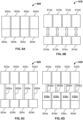
- FIG. 6A shows one embodiment of microfluidic reagent applicators 600 according to the disclosure.
- reagent reservoirs 602a, 602b, 602c, and 602d are integrated with corresponding droplet-on-demand microfluidic actuators 604a, 604b, 604c, and 604d.
- Microfluidic reagent applicators 600 can be disposable or refillable, and while shown as a group of four individual applicators, one or many more (such as corresponding to each of a number of steps of a staining protocol, which could be 5 or more, 10 or more or even 20 or more) can be combined in a single unit, and used, for example, with the substrate transport/substrate movement system 204 of FIG. 2 .
- groups of individual applicators can be used to simultaneously treat multiple samples, for example, some or all of a group of substrate mounted samples held in a tray holding 5 or more, 10 or more, or even 20 or more such substrate mounted samples.
- Microfluidic reagent applicators according to this embodiment can be added to and removed from an automated staining system in an entirely manual process or be used in combination with a reagent transport system for loading and unloading through an access port in an enclosure surrounding the staining system.
- FIG. 6B shows another embodiment of microfluidic reagent applicators 610 according to the disclosure.
- exchangeable reagent reservoirs 612a, 612b, 612c, and 612d are fluidically coupled with corresponding droplet-on-demand microfluidic actuators 614a, 614b, 614c, and 614d.
- Microfluidic reagent applicator reservoirs 612a, 612b, 612c, and 612d can be disposable or refillable, and, while shown in FIG 6B as a group of four individual applicators, one or more (such as corresponding to each of a number of steps of a staining protocol, which could be 5 or more, 10 or more or even 20 or more) can be combined in a single unit, and used, for example, with the substrate transport/substrate movement system 204, as illustrated in FIG. 2 .
- groups of individual applicators can be used to simultaneously treat multiple samples, for example, some or all of a group of substrate mounted samples held in a tray holding 5 or more, 10 or more, or even 20 or more such substrate mounted samples.
- Exchangeable reagent reservoirs 612a, 612b, 612c, and 612d can be added to and removed from an automated staining system in an entirely manual process or be used in combination with a reagent transport system for loading and unloading through an access port in an enclosure surrounding the staining system.
- FIG. 6C shows still another embodiment of microfluidic reagent applicators 620 according to the disclosure.
- remote reagent reservoirs 622a, 622b, 622c, and 622d are fluidically coupled with corresponding droplet-on-demand microfluidic actuators 624a, 624b, 624c, and 624d through fluid lines 626a, 626b, 626c, and 626d.
- Microfluidic reagent applicator reservoirs 622a, 622b, 622c, and 622d can be disposable or refillable, and while shown in FIG 6C as a group of four individual applicators, one or many more (such as corresponding to each of a number of steps of a staining protocol, which could be 5 or more, 10 or more or even 20 or more) can be combined in a single unit, and used, for example, with the substrate transport/substrate movement system 204 of FIG. 2 .
- groups of individual applicators can be used to simultaneously treat multiple samples, for example, some or all of a group of substrate mounted samples held in a tray holding 5 or more, 10 or more, or even 20 or more such substrate mounted samples.
- FIG. 6D shows a further embodiment of microfluidic reagent applicators 630 according to the disclosure.
- remote reagent reservoirs 632a, 632b, 632c, and 632d are fluidically coupled with corresponding droplet-on-demand microfluidic actuators 634a, 634b, 634c, and 634d through fluid lines 636a, 636b, 636c, and 636d.
- intermediate reservoirs 638a, 638b, 638c, and 638d are also included in this embodiment.
- Microfluidic reagent applicator reservoirs 632a, 632b, 632c, and 632d can be disposable or refillable, and while shown in FIG 6D as a group of four individual applicators, one or more (such as corresponding to each of a number of steps of a staining protocol, which could be 5 or more, 10 or more or even 20 or more) can be combined in a single unit, and used, for example, with the substrate transport/substrate movement system 204 of FIG. 2 .
- groups of individual applicators can be used to simultaneously treat multiple samples, for example, some or all of a group of substrate mounted samples held in a tray holding 5 or more, 10 or more, or even 20 or more such substrate mounted samples.
- Fluid lines 636a, 636b, 636c, and 636d can be rigid, flexible, or a combination of both rigid and flexible both between lines and within a single line.
- the embodiment of FIG. 6C is also appropriate for simultaneously treating all or a part of an array of samples such as is shown in FIG 3 if the lines are flexible.
- Such an arrangement also provides for the opportunity of refilling of the reservoirs from locations on the outside of an instrument, and as such can also be especially appropriate for dispensing of bulk fluids.
- remote reagent reservoirs 632a, 632b, 632c, and 632d can be replaced easily on the fly without interrupting processing of samples within the automated staining system.
- microfluidic reagent applicators shown and described with respect to FIGS 6A-6D can also be employed in a single automated biological sample staining system according to the disclosure.
- FIG. 7 schematically illustrates a reagent transport system 700 that can be used to move exchangeable fluid reservoirs 704 (such as shown in and described with reference to FIG 6B ), once decoupled from microfluidic actuators 702, to and from a reagent storage unit 720, which can be cooled to extend the life of reagents while not in use. Also illustrated is how the microfluidic reagent applicators (such as shown in and described with reference to FIG 6A ), including integrated reservoirs, 706 can be shuttled by reagent transport system 700 to and from a reagent storage unit 720.
- FIG. 7 schematically illustrates a reagent transport system 700 that can be used to move exchangeable fluid reservoirs 704 (such as shown in and described with reference to FIG 6B ), once decoupled from microfluidic actuators 702, to and from a reagent storage unit 720, which can be cooled to extend the life of reagents while not in use. Also illustrated is how the microfluidic reagent applicators
- FIG. 7 further illustrates how remote reagent reservoirs 708 can be kept in storage and used to feed the microfluidic reagent applicators 710 as needed through lines 712 and optional intermediate reservoirs (such as shown in and described with reference to FIGS. 6C and 6D ).
- FIG. 8 shows a microfluidic reagent applicator system 800 that includes a single droplet-on-demand actuator head 802 fluidically connected to a plurality of reagent reservoirs 804a, 804b, 804c, and 804d. Also shown in FIG. 8 is an embodiment of a sample substrate holder 806 onto/in which a substrate 808 bearing a sample 810 is placed onto a base 812, which base can be a heater base or a Peltier heating/cooling base. If compatible, the reagents contained in the plurality of reagent reservoirs 804a, 804b, 804c, and 804d can be applied sequentially to perform a staining protocol on sample 810.
- Such a simple configuration is suitable for a point-of-care system, such as a system for staining frozen tissue samples in surgical suite.
- a point-of-care system could, for example, be used by a surgeon to determine whether he/she has successfully removed a tumor past its margins from a patient.
- Reagent reservoirs 804a, 804b, 804c, and 804d can be integrated with droplet-on-demand actuator head 802, exchangeable with droplet-on-demand actuator head 802, or located remotely and connected fluidically via lines.
- FIG. 9A shows a front view of an embodiment of an integrated system including a microfluidic droplet-on-demand actuator, a bulk fluid applicator slit and a fluid aspirator slit.
- Reagent reservoir 902 is fluidically coupled to microfluidic reagent applicator head 906 as shown also in FIG 9B .
- a dual slit combination bulk fluid applicator and fluid aspirator 904 is mechanically coupled to microfluidic reagent applicator head 906.
- FIG. 9A shows a front view of FIG.
- hematoxylin and eosin which are generally not compatible in solution, can be co-dispensed using the systems and methods of the present disclosure.
- co-dispensing utilizing the systems and methods disclosed herein allows for a significant reduction in the number of assay steps (e.g. 10 steps to 5 steps) and a concomitant reduction in total volume of the assay (e.g. about 2.44mL/slide to about 1.26mL/slide), while yielding similar results.
- control system or control scheme includes an “Amplifier. "The generated waveform is amplified into an appropriate range of excitation potential (i.e. Voltage or Energy) to induce the ejection of a droplet.
- excitation potential i.e. Voltage or Energy
- control system or control scheme includes a "Fluid Droplet Dispenser- The amplified signal is passed to the corresponding nozzle and a droplet is fired from the nozzle, in step with the Relative Motion System onto the Droplet Target.
- control system or control scheme includes a "Droplet Target.”
- the control system or control scheme includes a CPU -
- the CPU in this case is a desktop computer.
- the role of the CPU is to coordinate the issuing of commands to the physical systems via Print Instructions and a Print Map. These are derived from a monochrome bitmap file, and the desired droplet print densities for the x and y axis directions.
- the x-axis print density is physically determined by setting the encoder step size for the Print Manager Board and the y axis print density is set by adjusting the saber angle of the print head. For example, 1000 x 1000-pixel image to be printed at 1000 x 1000 dpi would produce a print of 1 in2.
- the CPU provides speed information to the Relative Motion System as well as a y-step, and a starting position for the print job.
- the printing is system is locked into a "raster print" configuration, whereby the image is converted into a print on the Printing Target through successive printing moves in the x-direction followed by an incremental y-step movement prior to the next printing pass in the x direction.
- control system or control scheme includes a Print Instructions - Information about the print job to coordinate the Relative Motion System and Print Manager Board.
- control system or control scheme includes a Print Map - Monochromatic (i.e. binary) bitmap file where a logical True corresponds to a droplet dispense and a logical False corresponds to the lack of a droplet dispense.
- the Print Map is scaled using the x and y print densities when it is converted from a pixel map to an actual print (as described above in the CPU section).
- control system or control scheme includes a Print Manager Board - performs the role of the Digital Firing Pulse Generator function in the previous section.
- the board decomposes the Print Map to assign nozzles to fire for particular pixels in the map. Given information about the encoder step size, determines how many encoder pulses to wait between each pixel in the Print Map.
- this board and the Drive Card, with the Drive Cards effectively acting as daughterboard to the high-level function performed on the Print Manager Board.
- control system or control scheme includes Digital Firing Signals - The Print Manager Board, upon identifying that a droplet dispense operation must occur (via the deconstructed Print Map and monitoring the print head position with the Encoder Step Pulses as feedback), issues a command for a nozzle (or multiple nozzles in coordination), by issuing a firing signal down the corresponding data path to the nozzle's Drive Card.
- control system or control scheme includes a Drive Card - Performs the Waveform Generator and Amplifier functions described in the previous section.
- a Drive Card Performs the Waveform Generator and Amplifier functions described in the previous section.
- the Drive Card provides a dedicated signal line for each nozzle on the print head.
- the actual architecture may support a one-to-many association to the print heads since each signal line is mapped to a nozzle and is agnostic of whether those nozzles are co-located on the same print head.
- control system or control scheme includes Vector Graphics - in another embodiment a plotter approach and Vector Graphics (e.g. PostScript) language to describe the print operation may offer some benefits.
- Vector graphics describes lines and arcs for printing instead of pixels. This allows for infinite scaling and transformation of print images without a loss of resolution. It also allows for complex coordinated movement of the print system.
- Print operations may be programmatically defined (functions, loops, variables, etc.), instead of statically defined via image files. In this environment, for example, a print vector may be defined of a certain length, speed, firing frequency, and width of the print swath.
- Advantages refers to a common framework for describing all motion components for any operations the stainer needs to perform (washing, drying, etc.). Allows complex 2- or 3-axis printing operations. No need to perform sequential x-direction print operations followed by y steps. Easy to dilate and transform image of tissue into a print area or reuse an image from one slide to print another stain onto another slide with a cut of the same tissue.
- Multi-color bitmap Instead of individual monochromatic bitmaps for every print head and every print image to be applied to the sample, encode this information in a more complex image data file.
- the print operation may be encoded as a 64-bit bitmap, which allows for eight temporal print patterns to be mapped to eight unique print heads. May be a very efficient way to encode an entire complex assay in a very concise format. It could accommodate a large number of printed reagents, co-printing operations, ratiometric printing operations, gradient printing operations.
Landscapes
- Health & Medical Sciences (AREA)
- Chemical & Material Sciences (AREA)
- Life Sciences & Earth Sciences (AREA)
- Analytical Chemistry (AREA)
- General Health & Medical Sciences (AREA)
- Physics & Mathematics (AREA)
- Biochemistry (AREA)
- General Physics & Mathematics (AREA)
- Immunology (AREA)
- Pathology (AREA)
- Clinical Laboratory Science (AREA)
- Chemical Kinetics & Catalysis (AREA)
- Biomedical Technology (AREA)
- Molecular Biology (AREA)
- Engineering & Computer Science (AREA)
- Dispersion Chemistry (AREA)
- Hematology (AREA)
- Sampling And Sample Adjustment (AREA)
- Automatic Analysis And Handling Materials Therefor (AREA)
- Investigating Or Analysing Biological Materials (AREA)
Applications Claiming Priority (3)
| Application Number | Priority Date | Filing Date | Title |
|---|---|---|---|
| US201662410317P | 2016-10-19 | 2016-10-19 | |
| PCT/EP2017/076558 WO2018073283A1 (fr) | 2016-10-19 | 2017-10-18 | Systèmes et procédés de coloration d'échantillons biologiques |
| EP17790732.6A EP3529584B1 (fr) | 2016-10-19 | 2017-10-18 | Système de coloration d'échantillons biologiques |
Related Parent Applications (1)
| Application Number | Title | Priority Date | Filing Date |
|---|---|---|---|
| EP17790732.6A Division EP3529584B1 (fr) | 2016-10-19 | 2017-10-18 | Système de coloration d'échantillons biologiques |
Publications (2)
| Publication Number | Publication Date |
|---|---|
| EP4528287A2 true EP4528287A2 (fr) | 2025-03-26 |
| EP4528287A3 EP4528287A3 (fr) | 2025-04-16 |
Family
ID=60182553
Family Applications (2)
| Application Number | Title | Priority Date | Filing Date |
|---|---|---|---|
| EP24213921.0A Pending EP4528287A3 (fr) | 2016-10-19 | 2017-10-18 | Systèmes et procédés de coloration d'échantillons biologiques |
| EP17790732.6A Active EP3529584B1 (fr) | 2016-10-19 | 2017-10-18 | Système de coloration d'échantillons biologiques |
Family Applications After (1)
| Application Number | Title | Priority Date | Filing Date |
|---|---|---|---|
| EP17790732.6A Active EP3529584B1 (fr) | 2016-10-19 | 2017-10-18 | Système de coloration d'échantillons biologiques |
Country Status (5)
| Country | Link |
|---|---|
| US (2) | US11668726B2 (fr) |
| EP (2) | EP4528287A3 (fr) |
| JP (4) | JP7213802B2 (fr) |
| CN (1) | CN109844490A (fr) |
| WO (1) | WO2018073283A1 (fr) |
Families Citing this family (13)
| Publication number | Priority date | Publication date | Assignee | Title |
|---|---|---|---|---|
| EP3286543B1 (fr) | 2015-04-20 | 2023-03-29 | Ventana Medical Systems, Inc. | Dépôt par jet d'encre de réactifs pour échantillons histologiques |
| WO2018073283A1 (fr) | 2016-10-19 | 2018-04-26 | F. Hoffmann-La Roche Ag | Systèmes et procédés de coloration d'échantillons biologiques |
| CN108760448B (zh) * | 2018-05-31 | 2024-08-16 | 广州江元医疗科技有限公司 | 全自动阴道分泌物染色机 |
| CN113785184B (zh) * | 2019-05-14 | 2025-02-28 | 文塔纳医疗系统公司 | 包括生物学样品处理腔室的系统 |
| WO2021071491A1 (fr) | 2019-10-10 | 2021-04-15 | Hewlett-Packard Development Company, L.P. | Distributeurs microfluidiques de limitation de dilution |
| JP7520981B2 (ja) * | 2019-12-31 | 2024-07-23 | サクラ ファインテック ユー.エス.エー., インコーポレイテッド | 自動化染色システム及び反応室 |
| CN111157433A (zh) * | 2020-01-06 | 2020-05-15 | 中国科学院生态环境研究中心 | 用于红细胞的单个细胞标记的试剂盒及其检测方法 |
| US20230236211A1 (en) * | 2020-06-12 | 2023-07-27 | Agilent Technologies, Inc. | Systems and methods for coverslipping slides |
| CN113933134A (zh) * | 2020-07-14 | 2022-01-14 | 深圳迈瑞生物医疗电子股份有限公司 | 一种用于样本染色的染色方法以及相关设备 |
| WO2022102748A1 (fr) * | 2020-11-12 | 2022-05-19 | 株式会社GramEye | Dispositif d'aide à l'examen microscopique, procédé d'aide à l'examen microscopique, dispositif de teinture automatique, système d'estimation de substance colorante automatique, programme et support d'enregistrement |
| US12226776B2 (en) | 2021-11-04 | 2025-02-18 | Instrumentation Laboratory Company | Preparing substances in a medical diagnostic system |
| CN114877666A (zh) * | 2022-02-25 | 2022-08-09 | 南京华易泰电子科技有限公司 | 一种适用于面板干燥用的双缝气刀结构及其加工工艺 |
| WO2023225048A1 (fr) * | 2022-05-17 | 2023-11-23 | Synthego Corporation | Systèmes et procédés pour plateformes et modules pouvant venir en prise pour le traitement de cellules |
Citations (2)
| Publication number | Priority date | Publication date | Assignee | Title |
|---|---|---|---|---|
| US8883509B2 (en) | 2007-07-10 | 2014-11-11 | Ventana Medical Systems, Inc. | Apparatus and method for biological sample processing |
| WO2015086534A1 (fr) | 2013-12-13 | 2015-06-18 | Ventana Medical Systems, Inc. | Réactifs de coloration et autres liquides pour traitement histologique de spécimens biologiques et technologie associée |
Family Cites Families (54)
| Publication number | Priority date | Publication date | Assignee | Title |
|---|---|---|---|---|
| US2896237A (en) | 1957-01-11 | 1959-07-28 | Int Latex Corp | Flexible container |
| DE3683573D1 (de) | 1985-06-26 | 1992-03-05 | Japan Tectron Instr Corp | Automatischer analysenapparat. |
| US4624148A (en) | 1985-09-20 | 1986-11-25 | Dynatech Precision Sampling Corporation | Automatic fluid injector |
| US4877745A (en) | 1986-11-17 | 1989-10-31 | Abbott Laboratories | Apparatus and process for reagent fluid dispensing and printing |
| US4914022A (en) | 1987-10-21 | 1990-04-03 | Amc Cancer Research Center | Method for preparing multiple tissue samples for microscopic investigation and testing |
| JP3320444B2 (ja) | 1992-04-06 | 2002-09-03 | 株式会社千代田製作所 | 染色装置用ノズル洗浄装置 |
| US5658802A (en) | 1995-09-07 | 1997-08-19 | Microfab Technologies, Inc. | Method and apparatus for making miniaturized diagnostic arrays |
| US6664044B1 (en) | 1997-06-19 | 2003-12-16 | Toyota Jidosha Kabushiki Kaisha | Method for conducting PCR protected from evaporation |
| US6699710B1 (en) | 1998-02-25 | 2004-03-02 | The United States Of America As Represented By The Department Of Health And Human Services | Tumor tissue microarrays for rapid molecular profiling |
| JP3474774B2 (ja) | 1998-05-29 | 2003-12-08 | リコーマイクロエレクトロニクス株式会社 | インクジェットヘッドのノズルプレートの製造方法 |
| AU2001234739A1 (en) | 2000-02-02 | 2001-08-14 | Cartesian Technologies, Inc. | Method and apparatus for developing dna microarrays |
| AU2002216618A1 (en) * | 2000-10-06 | 2002-04-15 | Protasis Corporation | Fluid separation conduit cartridge with encryption capability |
| AU2001296809A1 (en) | 2000-10-10 | 2002-04-22 | Biotrove, Inc. | Apparatus for assay, synthesis and storage, and methods of manufacture, use, and manipulation thereof |
| JP2002267675A (ja) * | 2001-03-14 | 2002-09-18 | Hitachi Ltd | 自動分析装置 |
| US20020180475A1 (en) | 2001-03-28 | 2002-12-05 | Hidenori Watanabe | Manufacturing method and apparatus for probe carriers |
| JP2003004609A (ja) | 2001-03-28 | 2003-01-08 | Canon Inc | プローブ担体の製造方法および製造装置 |
| JP3902939B2 (ja) * | 2001-10-26 | 2007-04-11 | 株式会社日立ハイテクノロジーズ | 標本中の微小領域測定装置及び方法 |
| US7141368B2 (en) | 2002-01-30 | 2006-11-28 | Agilent Technologies, Inc. | Multi-directional deposition in array fabrication |
| DE60303504T2 (de) | 2002-02-22 | 2006-10-12 | Biodot, Inc., Irvine | Verfahren und vorrichtung zur kontaktlosen tröpfchenabgabe unterhalb einer fluidischen oberfläche |
| US7468161B2 (en) | 2002-04-15 | 2008-12-23 | Ventana Medical Systems, Inc. | Automated high volume slide processing system |
| ES2556242T3 (es) | 2002-04-26 | 2016-01-14 | Ventana Medical Systems, Inc. | Aparato de patología molecular automatizado que tiene plataformas de portaobjetos fijas |
| FR2843048B1 (fr) | 2002-08-01 | 2004-09-24 | Commissariat Energie Atomique | Dispositif d'injection et de melange de micro-gouttes liquides. |
| JP4457742B2 (ja) | 2003-04-30 | 2010-04-28 | 株式会社島津製作所 | 生体標本への試薬の分注方法及び生体標本の解析方法 |
| WO2004111610A2 (fr) | 2003-06-12 | 2004-12-23 | Accupath Diagnostic Laboratories, Inc. | Procede et systeme pour l'analyse d'echantillons de cellules de forte densite |
| CN1965223A (zh) | 2004-03-02 | 2007-05-16 | 丹麦达科有限公司 | 用于生物学着色仪的试剂传送系统、释放设备和容器 |
| US20060105453A1 (en) | 2004-09-09 | 2006-05-18 | Brenan Colin J | Coating process for microfluidic sample arrays |
| EP1805027A4 (fr) | 2004-10-28 | 2010-05-05 | Ricoh Kk | Appareil d enregistrement à jet d encre et procédé d enregistrement à jet d encre |
| JP2006126013A (ja) | 2004-10-28 | 2006-05-18 | Shimadzu Corp | プロテオーム解析装置 |
| DE102006007542B3 (de) | 2006-02-16 | 2007-09-20 | Dionex Softron Gmbh | Verfahren und Vorrichtung zum Ansaugen eines Flüssigkeitsvolumens, insbesondere zur Entnahme einer Probe zur Analyse mittels einer Flüssigkeitschromatographievorrichtung |
| JP4861788B2 (ja) | 2006-10-11 | 2012-01-25 | キヤノン株式会社 | 生体標本の処理方法及び解析方法 |
| US7867450B2 (en) | 2006-11-08 | 2011-01-11 | Seiko Epson Corporation | Liquid droplet ejecting head, inspection device, and method of using inspection device |
| JP4910727B2 (ja) * | 2007-01-31 | 2012-04-04 | セイコーエプソン株式会社 | 検査装置 |
| WO2008063135A1 (fr) | 2006-11-24 | 2008-05-29 | Agency For Science, Technology And Research | Appareil pour traiter un échantillon dans une gouttelette de liquide et procédé d'utilisation |
| JP5014780B2 (ja) | 2006-12-28 | 2012-08-29 | 株式会社先端生命科学研究所 | メチル化ヘテロジニアス・ヌクレア・リボヌクレオプロテインの免疫学的分析方法及びその利用 |
| EP2130023B1 (fr) | 2007-03-15 | 2015-05-06 | Ventana Medical Systems, Inc. | Hématoxyline stabilisée |
| US8304254B2 (en) | 2007-05-02 | 2012-11-06 | Siemens Healthcare Diagnostics Inc. | Piezo dispensing of a diagnostic liquid onto a reagent surface |
| JP2009058437A (ja) | 2007-08-31 | 2009-03-19 | Olympus Corp | 分注ノズル及び自動分析装置 |
| US8340389B2 (en) | 2008-11-26 | 2012-12-25 | Agilent Technologies, Inc. | Cellular- or sub-cellular-based visualization information using virtual stains |
| JP5097737B2 (ja) | 2009-03-27 | 2012-12-12 | 株式会社日立ハイテクノロジーズ | 自動分析装置及びサンプル分注ノズル |
| JP4936235B2 (ja) | 2009-12-21 | 2012-05-23 | 株式会社日立プラントテクノロジー | 発光測定装置の試薬開封機構および試薬開封機構における開封針制御方法 |
| ES2477228T3 (es) * | 2009-12-22 | 2014-07-16 | Bridgestone Corporation | Composición mejorada de un modificador vin�lico y procedimientos para utilizarla |
| US20120122197A1 (en) | 2010-11-12 | 2012-05-17 | Abner David Jospeh | Inkjet reagent deposition for biosensor manufacturing |
| WO2012066827A1 (fr) * | 2010-11-19 | 2012-05-24 | オリンパス株式会社 | Procédé de préparation d'un échantillon biologique |
| JP5707253B2 (ja) | 2011-06-27 | 2015-04-22 | 株式会社日立ハイテクノロジーズ | 冷却試薬保管庫及び核酸分析装置 |
| AU2012339620B2 (en) | 2011-11-16 | 2016-01-28 | Leica Biosystems Melbourne Pty Ltd | An automated system and method of treating tissue samples on slides |
| JP5878377B2 (ja) | 2012-01-16 | 2016-03-08 | シスメックス株式会社 | 分析装置 |
| KR20140025152A (ko) | 2012-08-21 | 2014-03-04 | 주식회사 피치텍 | 피부치료용 광 조사기 |
| AU2014248018A1 (en) | 2013-04-05 | 2015-08-20 | Roche Diagnostics Hematology, Inc. | Automated systems and methods for preparing biological specimens for examination |
| ES2523397B1 (es) | 2013-05-24 | 2015-09-10 | Fundació Cetemmsa | Composición de tinta para impresión por inyección |
| JP6191270B2 (ja) * | 2013-06-20 | 2017-09-06 | コニカミノルタ株式会社 | 自動染色処理装置 |
| CN106716104B (zh) | 2014-09-22 | 2020-12-22 | 株式会社日冷生物科学 | 自动组织染色装置和自动组织染色方法 |
| CN105890959A (zh) | 2014-11-24 | 2016-08-24 | 王素蓉 | 染色仪及染色仪的控制方法 |
| EP3286543B1 (fr) | 2015-04-20 | 2023-03-29 | Ventana Medical Systems, Inc. | Dépôt par jet d'encre de réactifs pour échantillons histologiques |
| WO2018073283A1 (fr) * | 2016-10-19 | 2018-04-26 | F. Hoffmann-La Roche Ag | Systèmes et procédés de coloration d'échantillons biologiques |
-
2017
- 2017-10-18 WO PCT/EP2017/076558 patent/WO2018073283A1/fr not_active Ceased
- 2017-10-18 EP EP24213921.0A patent/EP4528287A3/fr active Pending
- 2017-10-18 JP JP2019520837A patent/JP7213802B2/ja active Active
- 2017-10-18 CN CN201780064571.3A patent/CN109844490A/zh active Pending
- 2017-10-18 EP EP17790732.6A patent/EP3529584B1/fr active Active
-
2019
- 2019-04-18 US US16/388,797 patent/US11668726B2/en active Active
-
2022
- 2022-06-06 JP JP2022091692A patent/JP7420868B2/ja active Active
-
2023
- 2023-04-20 US US18/137,254 patent/US12517148B2/en active Active
-
2024
- 2024-01-11 JP JP2024002261A patent/JP7704904B2/ja active Active
-
2025
- 2025-06-26 JP JP2025107877A patent/JP2025138764A/ja active Pending
Patent Citations (2)
| Publication number | Priority date | Publication date | Assignee | Title |
|---|---|---|---|---|
| US8883509B2 (en) | 2007-07-10 | 2014-11-11 | Ventana Medical Systems, Inc. | Apparatus and method for biological sample processing |
| WO2015086534A1 (fr) | 2013-12-13 | 2015-06-18 | Ventana Medical Systems, Inc. | Réactifs de coloration et autres liquides pour traitement histologique de spécimens biologiques et technologie associée |
Non-Patent Citations (2)
| Title |
|---|
| LOVCHIK ET AL., 15TH INT. CONF. ON MINIATURIZED SYSTEMS FOR CHEMISTRY AND LIFE SCIENCES, vol. 201, pages 368 - 370 |
| PEPPER, JOURNAL OF HISTOLOGY, vol. 34, no. 3, 2011, pages 123 - 131 |
Also Published As
| Publication number | Publication date |
|---|---|
| US12517148B2 (en) | 2026-01-06 |
| JP2022119988A (ja) | 2022-08-17 |
| JP2025138764A (ja) | 2025-09-25 |
| JP7420868B2 (ja) | 2024-01-23 |
| US11668726B2 (en) | 2023-06-06 |
| EP4528287A3 (fr) | 2025-04-16 |
| CN109844490A (zh) | 2019-06-04 |
| EP3529584A1 (fr) | 2019-08-28 |
| JP2019536010A (ja) | 2019-12-12 |
| EP3529584B1 (fr) | 2024-11-27 |
| JP7213802B2 (ja) | 2023-01-27 |
| US20230258680A1 (en) | 2023-08-17 |
| JP2024041893A (ja) | 2024-03-27 |
| US20190242921A1 (en) | 2019-08-08 |
| JP7704904B2 (ja) | 2025-07-08 |
| WO2018073283A1 (fr) | 2018-04-26 |
Similar Documents
| Publication | Publication Date | Title |
|---|---|---|
| US12517148B2 (en) | Systems and methods for staining of biological samples | |
| US8303915B2 (en) | Thin film apparatus and method | |
| EP3324171B1 (fr) | Méthode automatique de traitement de lames à haut débit | |
| EP3126847B1 (fr) | Systèmes automatisés de traitement d'échantillons et traitement en plusieurs étapes de lames de microscope | |
| WO2014130576A1 (fr) | Analyse fish automatique d'échantillons de tissus et de cellules à l'aide d'une barrière d'isolation pour la distribution précise d'une sonde et d'autres réactifs sur des régions d'intérêt | |
| EP3824265B1 (fr) | Système de coloration automatisé | |
| US11030758B2 (en) | Method and apparatus for registering images of histological sections | |
| JP7640602B2 (ja) | 変調式空気ジェットを使用する非接触混合 | |
| WO2001022086A1 (fr) | Systeme a haut debit pour l'evaluation de l'utilite clinique de cibles moleculaires dans des echantillons de tissus | |
| US12436068B2 (en) | 3D-printed mask for lysing at a location on a tissue section | |
| WO2009127394A2 (fr) | Dispositif automatique pour la mise en œuvre de réactions de détection, et procédé de dosage de réactifs sur des porte-objets |
Legal Events
| Date | Code | Title | Description |
|---|---|---|---|
| PUAI | Public reference made under article 153(3) epc to a published international application that has entered the european phase |
Free format text: ORIGINAL CODE: 0009012 |
|
| STAA | Information on the status of an ep patent application or granted ep patent |
Free format text: STATUS: THE APPLICATION HAS BEEN PUBLISHED |
|
| REG | Reference to a national code |
Ref country code: DE Ref legal event code: R079 Free format text: PREVIOUS MAIN CLASS: G01N0035100000 Ipc: G01N0001310000 |
|
| PUAL | Search report despatched |
Free format text: ORIGINAL CODE: 0009013 |
|
| AC | Divisional application: reference to earlier application |
Ref document number: 3529584 Country of ref document: EP Kind code of ref document: P |
|
| AK | Designated contracting states |
Kind code of ref document: A2 Designated state(s): AL AT BE BG CH CY CZ DE DK EE ES FI FR GB GR HR HU IE IS IT LI LT LU LV MC MK MT NL NO PL PT RO RS SE SI SK SM TR |
|
| AK | Designated contracting states |
Kind code of ref document: A3 Designated state(s): AL AT BE BG CH CY CZ DE DK EE ES FI FR GB GR HR HU IE IS IT LI LT LU LV MC MK MT NL NO PL PT RO RS SE SI SK SM TR |
|
| RIC1 | Information provided on ipc code assigned before grant |
Ipc: B01L 9/00 20060101ALI20250313BHEP Ipc: B01L 3/00 20060101ALI20250313BHEP Ipc: B01L 3/02 20060101ALI20250313BHEP Ipc: G01N 35/10 20060101ALI20250313BHEP Ipc: G01N 1/31 20060101AFI20250313BHEP |
|
| STAA | Information on the status of an ep patent application or granted ep patent |
Free format text: STATUS: REQUEST FOR EXAMINATION WAS MADE |
|
| 17P | Request for examination filed |
Effective date: 20251008 |