EP4528323A1 - Capteur optique - Google Patents
Capteur optique Download PDFInfo
- Publication number
- EP4528323A1 EP4528323A1 EP23198693.6A EP23198693A EP4528323A1 EP 4528323 A1 EP4528323 A1 EP 4528323A1 EP 23198693 A EP23198693 A EP 23198693A EP 4528323 A1 EP4528323 A1 EP 4528323A1
- Authority
- EP
- European Patent Office
- Prior art keywords
- optical sensor
- light beams
- control
- sensor
- receiver
- Prior art date
- Legal status (The legal status is an assumption and is not a legal conclusion. Google has not performed a legal analysis and makes no representation as to the accuracy of the status listed.)
- Pending
Links
- 230000003287 optical effect Effects 0.000 title claims abstract description 113
- 238000001514 detection method Methods 0.000 claims abstract description 65
- 238000012544 monitoring process Methods 0.000 claims abstract description 43
- 238000011156 evaluation Methods 0.000 claims abstract description 16
- 230000001681 protective effect Effects 0.000 claims description 33
- 230000003247 decreasing effect Effects 0.000 claims description 3
- 238000000034 method Methods 0.000 claims description 3
- 238000011109 contamination Methods 0.000 description 29
- 230000005540 biological transmission Effects 0.000 description 5
- 238000013461 design Methods 0.000 description 5
- 238000005259 measurement Methods 0.000 description 5
- 230000007423 decrease Effects 0.000 description 3
- 230000001419 dependent effect Effects 0.000 description 3
- 230000000875 corresponding effect Effects 0.000 description 2
- 230000007704 transition Effects 0.000 description 2
- 230000032683 aging Effects 0.000 description 1
- 230000002596 correlated effect Effects 0.000 description 1
- 238000011161 development Methods 0.000 description 1
- 230000018109 developmental process Effects 0.000 description 1
- 230000007613 environmental effect Effects 0.000 description 1
- 230000035945 sensitivity Effects 0.000 description 1
- 238000002366 time-of-flight method Methods 0.000 description 1
Images


Classifications
-
- G—PHYSICS
- G01—MEASURING; TESTING
- G01S—RADIO DIRECTION-FINDING; RADIO NAVIGATION; DETERMINING DISTANCE OR VELOCITY BY USE OF RADIO WAVES; LOCATING OR PRESENCE-DETECTING BY USE OF THE REFLECTION OR RERADIATION OF RADIO WAVES; ANALOGOUS ARRANGEMENTS USING OTHER WAVES
- G01S7/00—Details of systems according to groups G01S13/00, G01S15/00, G01S17/00
- G01S7/48—Details of systems according to groups G01S13/00, G01S15/00, G01S17/00 of systems according to group G01S17/00
- G01S7/497—Means for monitoring or calibrating
-
- G—PHYSICS
- G01—MEASURING; TESTING
- G01S—RADIO DIRECTION-FINDING; RADIO NAVIGATION; DETERMINING DISTANCE OR VELOCITY BY USE OF RADIO WAVES; LOCATING OR PRESENCE-DETECTING BY USE OF THE REFLECTION OR RERADIATION OF RADIO WAVES; ANALOGOUS ARRANGEMENTS USING OTHER WAVES
- G01S17/00—Systems using the reflection or reradiation of electromagnetic waves other than radio waves, e.g. lidar systems
- G01S17/02—Systems using the reflection of electromagnetic waves other than radio waves
- G01S17/06—Systems determining position data of a target
- G01S17/42—Simultaneous measurement of distance and other co-ordinates
-
- G—PHYSICS
- G01—MEASURING; TESTING
- G01S—RADIO DIRECTION-FINDING; RADIO NAVIGATION; DETERMINING DISTANCE OR VELOCITY BY USE OF RADIO WAVES; LOCATING OR PRESENCE-DETECTING BY USE OF THE REFLECTION OR RERADIATION OF RADIO WAVES; ANALOGOUS ARRANGEMENTS USING OTHER WAVES
- G01S17/00—Systems using the reflection or reradiation of electromagnetic waves other than radio waves, e.g. lidar systems
- G01S17/88—Lidar systems specially adapted for specific applications
- G01S17/93—Lidar systems specially adapted for specific applications for anti-collision purposes
- G01S17/931—Lidar systems specially adapted for specific applications for anti-collision purposes of land vehicles
-
- G—PHYSICS
- G01—MEASURING; TESTING
- G01S—RADIO DIRECTION-FINDING; RADIO NAVIGATION; DETERMINING DISTANCE OR VELOCITY BY USE OF RADIO WAVES; LOCATING OR PRESENCE-DETECTING BY USE OF THE REFLECTION OR RERADIATION OF RADIO WAVES; ANALOGOUS ARRANGEMENTS USING OTHER WAVES
- G01S7/00—Details of systems according to groups G01S13/00, G01S15/00, G01S17/00
- G01S7/48—Details of systems according to groups G01S13/00, G01S15/00, G01S17/00 of systems according to group G01S17/00
- G01S7/497—Means for monitoring or calibrating
- G01S2007/4975—Means for monitoring or calibrating of sensor obstruction by, e.g. dirt- or ice-coating, e.g. by reflection measurement on front-screen
Definitions
- the invention relates to an optical sensor and a method for detecting objects in a surveillance area by means of an optical sensor.
- optical sensors are generally used for monitoring purposes.
- the optical sensor is designed as a safety sensor, which is used in safety-related applications.
- the optical sensor comprises a housing with a front pane, in which at least one transmitter emitting light beams and at least one receiver receiving light beams are present. Light beams emitted by the transmitter are guided through the front pane into the monitoring area, and light beams reflected by an object are guided across the front pane to the receiver. Furthermore, the optical sensor comprises an evaluation unit in which, depending on the received signals from the receiver, an object detection signal is generated, which is output via an output.
- An example of such an optical sensor is an area distance sensor, i.e. a scanning distance sensor.
- the housing of the area distance sensor also contains a deflection unit with which the light beams are periodically guided in a scanning direction within a certain angular range.
- the normative requirements for detection reliability stipulate that a diffusely reflecting object with a remission of 1.8% is detected within a maximum range of the optical sensor with a defined detection reliability under regular operating conditions, i.e. taking into account environmental conditions, aging of components and external interference.
- Contamination of the front window that occurs during operation of the optical sensor reduces the level of the received signals during object detection, which leads to a reduction in detection reliability.
- Optical window monitoring units are commonly used with optical sensors to detect the degree of contamination on the windshield.
- the window monitoring unit comprises a control sensor with a control transmitter that emits control light beams and a control receiver that receives control light beams, which measures the transmission of the control light beams passing through the windshield.
- the level of the received signals at the control receiver is correlated with the level of the received signals.
- the lower the level of the received signals of the control receiver the greater the contamination of the windscreen and the lower the level of the received signals of the receiver.
- Window monitoring units determine a limit value that falls below a minimum level and switches off.
- window monitoring units that assess windshield contamination by measuring the light generated by the contamination.
- the level of the control receiver's received signals increases with the degree of contamination on the window cover.
- a threshold is a maximum level, which, if exceeded, triggers shutdown.
- the optical sensor is designed for a maximum range at which a defined level of the receiver's received signals is still present, ensuring a certain level of detection reliability.
- a limit value for the level of the control receiver's received signals is defined and preset in the evaluation unit. This limit defines the maximum permissible contamination of the windscreen. If the limit value is reached due to contamination of the windscreen during operation of the optical sensor, the optical sensor enters a safe state. For example, the safe switching outputs of the optical sensor are switched off.
- optical sensor In many applications of the optical sensor, it is not necessary to perform object detection up to the maximum possible range of the optical sensor. Rather, it is often sufficient to perform object monitoring at smaller distances.
- One example of this is a Protective field monitoring performed with an area distance sensor. The edge of the protective field, within which object monitoring is performed, is typically at a distance smaller than the maximum range of the optical sensor.
- the limit value for contamination is designed for the maximum range of the optical sensor, which is why the optical sensor switches to the safe state when contamination occurs, even if reliable object detection would still be possible within the protective field.
- the invention is based on the object of providing an optical sensor of the type mentioned above which has a high level of functional reliability and, at the same time, a high level of availability.
- the invention relates to an optical sensor for detecting objects in a surveillance area, comprising a housing having a front pane, in which at least one transmitter emitting light beams and at least one receiver receiving light beams are present. Light beams emitted by the transmitter are guided through the front pane into the surveillance area. Light beams reflected by an object are guided via the front pane to the receiver.
- the optical sensor further comprises an evaluation unit, in which an object detection signal is generated depending on received signals from the receiver, which signal is output via an output.
- An optical window monitoring unit is provided, by means of which soiling of the front pane is detected. The optical sensor automatically switches to a safe state when a limit value for the degree of soiling of the windscreen is detected, whereby the limit value is specified depending on a maximum detection distance.
- the invention also relates to a corresponding method.
- the optical sensor according to the invention is designed for use in safety-relevant applications and meets the normative requirements for detection reliability during object detection. It is ensured that a diffusely reflecting object with a remission of 1.8% is detected with the normatively required detection reliability in all object detections.
- the optical sensor is particularly advantageous as a safety sensor.
- the safety sensor has a fail-safe design. This can be achieved through a redundant, particularly multi-channel, design of the evaluation unit and the output of the optical sensor.
- the optical sensor can be used, in particular, to control the operation of a system that could pose a hazard to people.
- the optical sensor then monitors a specific distance range in the system's vicinity. Depending on whether or not an object is detected within the distance range, a binary switching signal is generated in the evaluation unit as an object detection signal, which is then output to the system via the safe output. If an object is detected within the distance range, a shutdown command is generated as a switching signal, which shuts down the system so that it no longer poses any hazards.
- the optical sensor according to the invention can be designed, for example, in the form of a distance sensor or camera sensor.
- the optical sensor is an area distance sensor, with which a protective field monitoring is carried out within a protective field.
- the maximum detection distance is formed by an edge of a protective field
- the optical sensor according to the invention includes an optical window monitoring unit for detecting contamination of the windshield. According to the invention, the optical sensor automatically enters a safe state when the window monitoring unit detects a threshold value for the degree of contamination of the windshield, with the threshold value being predetermined depending on a maximum detection distance.
- the optical window monitoring unit detects contamination that impairs the detection reliability of the optical sensor.
- the limit value for permissible contamination is not related to the maximum range of the optical sensor, but rather to the maximum detection distance required in the respective application, which is typically smaller than the maximum range.
- the maximum detection distance specified in the evaluation unit is specifically specified for the respective application and stored in the evaluation unit.
- a limit value related to the maximum range would lead to an unnecessary transition to the safe state of the optical sensor if it is only used to detect objects within a maximum detection distance that is smaller than the maximum range.
- the limit value related to the maximum detection distance ensures that the normative requirements for detection reliability are always met, as object detections at distances greater than the maximum detection distance, at which detection reliability is no longer guaranteed due to contamination, are excluded. Conversely, the limit value related to the maximum detection distance ensures that the required detection reliability is met for all object detections within the maximum detection distance during operation of the optical sensor; otherwise, the optical sensor would immediately enter the safe state.
- variable limit value for the window monitoring unit which is adapted to the respective application, prevents an unnecessary transition of the optical sensor to the safe state, thus avoiding unnecessary downtimes of the optical sensor or of a system monitored by the optical sensor.
- the safe state is advantageously realized by switching off the safe output or by issuing a switch-off command at the output.
- the window monitoring unit has at least one control sensor with a control transmitter emitting control light beams and a control receiver receiving control light beams.
- control receiver registers control light beams from the control transmitter passing through the windscreen.
- transmission measurements are used to detect contamination on the windscreen.
- control receiver registers control light beams from the control transmitter reflected on the windscreen.
- reflection measurements are used to detect dirt on the windscreen.
- the light beams from the transmitter are periodically guided in a scanning direction within an angular range and through the windshield.
- several control sensors are arranged stationary and offset in the scanning direction.
- a control sensor is provided whose optical arrangement allows movement in the scanning direction, i.e., the control sensor is arranged in a rotating manner.
- the control sensor can also consist of a stationary and a rotating transmitting and receiving device.
- control sensors which are arranged at a distance from one another in the scanning direction, allow a large part of the windscreen to be monitored for dirt.
- the protective field edge defines the maximum detection distance.
- the edge of the protective field is at different distances from the optical sensor at different angles of the light beams.
- a simple example of this is a rectangular protective field.
- a limit value for the degree of contamination is specified for each control sensor depending on a maximum detection distance, or, in the case of a co-rotating control sensor, angle range-dependent contamination levels are specified.
- Each control sensor is assigned to an angular segment of the angular range, and the limit value is defined depending on the edge of the protective field in this angular segment.
- the maximum detection distance is thus formed by the distance between the edge of the protective field and the optical sensor in the respective angular segment in which the control sensor detects the contamination.
- the maximum detection distance can be varied in an optimized distance range in which the levels of the received signals of the receiver during object detection form a strictly monotonically decreasing function with the distance to the optical sensor.
- a monotonically decreasing curve of the received signal levels as a function of the object distance is a prerequisite for a clear assignment of contamination monitoring thresholds to the maximum detection distance.
- the range in which the received signal level decreases strictly monotonically with the object distance is advantageously maximized by appropriate design measures, such as optical elements such as lenses.
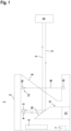
- the Figures 1 and 2 show an embodiment of the optical sensor 1 according to the invention.
- the optical sensor 1 is used for object monitoring in a surveillance area.
- the sensor components of the optical sensor 1 are housed in a housing 2.
- the optical sensor 1 can be designed, for example, in the form of a camera sensor or in the form of a 1D distance sensor.
- the optical sensor 1 is designed as an area distance sensor.
- the area distance sensor has a transmitter 4 emitting light beams 3 and a receiver 5 receiving light beams 3, which form a distance sensor.
- the distance sensor performs distance measurements using a pulse-time-of-flight method.
- the transmitter 4 emits light beams 3 in the form of light pulses.
- the distance of an object O from the optical sensor 1, the time of flight of the light pulses to the object O and back to the optical sensor 1, is then recorded and evaluated in the evaluation unit 6.
- the distance measurement can be carried out according to the phase measurement principle.
- An evaluation unit 6 for evaluating received signals from the receiver 5 is arranged in the housing 2.
- the optical sensor 1 is designed as a safety sensor.
- the evaluation unit 6 has a redundant structure, for example, in the form of two computer units that cyclically monitor each other.
- an object detection signal is generated depending on the received signals from the receiver 5, which is output via an output 7, for example to a system monitored by the optical sensor 1.
- the output 7 also has a fail-safe, for example redundant, design.
- a transparent front panel 8 is integrated in the housing 2, through which the light rays 3 are guided.
- the light beams 3 of the transmitter 4 pass through the front screen 8 and are periodically scanned in a scanning direction (arrow I in Figure 2 ) within an angular range which in this case is limited by the extent of the front screen 8 in the scanning direction.
- the angular range is approximately 275°, as can be seen from Figure 2 visible.
- Light rays 3 reflected from an object O are guided back to the receiver through the front screen 8.
- the deflection of the light beams 3 is achieved by means of a deflection unit 9, which has a deflection mirror 10 for deflecting the light beams 3.
- the deflection mirror 10 is set in rotation by an electric drive unit 11. The rotation occurs about a rotation axis D.
- the optical sensor 1 monitors the protective field. As can be seen from Figure 2 For this purpose, a protective field 12 is activated in the optical sensor 1, preferably by selecting several stored protective fields 12.
- a binary switching signal is generated as an object detection signal, the switching states of which indicate whether an object O is located in the protective field 12 or not. If an object O is located in the protective field 12, a shutdown command is generated as a switching signal, which shuts down a system monitored by the optical sensor 1.
- An optical window monitoring unit is provided for detecting and monitoring soiling.
- the window monitoring unit comprises at least one monitoring sensor 13, which can detect soiling on the windscreen 8.
- several monitoring sensors 13 are provided, which are arranged one behind the other in the scanning direction in the area of the windscreen 8.
- Each control sensor 13 comprises a control transmitter 15 emitting control light beams 14 and a control receiver 16 receiving control light beams 14.
- Each control sensor 13 of the optical sensor 1 according to Figure 1 operates according to the transmission principle.
- Such a system based on the transmission principle can alternatively be implemented by arranging the control transmitter 15 and control sensor 16 next to each other in the upper or lower part of the building 2, and guiding the control light beams over an oppositely arranged mirror or reflector and then passing through the front pane 14 twice.
- control light beams 14 of the control transmitter 15 pass through the windscreen 8 once and are then guided to the control receiver 16.
- the level of the received signals of the control receiver 16 is lower the more soiled the windscreen 8 is.
- Figure 3 shows a variant of the optical sensor 1.
- the embodiment of the Figure 3 differs from the embodiment according to Figure 1 only with regard to the design of the control sensors 13.
- Each control sensor 13 according to Figure 3 works according to the reflection principle.
- control light beams 14 emitted by the control transmitter 15 are partially reflected on the front screen 8, depending on the degree of soiling, and are guided to the control receiver 16.
- the level of the received signals from the control receiver 16 is greater the more soiled the front screen 8 is.
- the control transmitter 15 and control receiver 16 can also be located within the enclosed area of the device; in this case, the path of the control light beams 14 runs within the device.
- a contamination limit is defined for both embodiments of the window monitoring unit for the control sensors 13. If the contamination limit is reached for at least one of the control sensors 13, reliable object detection is no longer guaranteed, and the optical sensor 1 is automatically transferred to a safe state.
- the safe state is advantageously realized by switching off output 7 or by issuing a switch-off command at output 7.
- the limit value of contamination is specified in accordance with the requirements for detection reliability.
- Figure 4 shows the course of the reception level E, ie the level of the reception signals of the receiver 5 of the optical sensor 1 depending on the object distance, when an object O with a defined remission of 1.8% is detected.
- the reception level E of receiver 5 decreases strictly monotonically with the object distance in a long-range range (at distances d > D).
- the size of this range is preferably maximized by using suitable optical elements.
- the reception level E In the short-range range, at distances d ⁇ D, the reception level E generally does not exhibit a monotonic progression, caused by adapted optical components/systems that improve the detection capability at short distances.
- the sensor at maximum range d max (see Figure 4 ) can still reliably detect an object, even if the front windscreen 8 is somewhat dirty. This means that even with this dirt, the minimum level E min for reliable detection by the receiver 5 is still achieved.
- This level of permissible contamination includes a corresponding level of the window monitoring system's control system, E min . If the contamination continues to increase, E min and thus reliable detection are no longer achieved. Therefore, E min is used as the window monitoring system's limit value. If the level is exceeded, the sensor enters a safe state, shutting down the system.
- the limit value for the contamination E min that is detected by the control sensor(s) 13 is not fixedly related to the maximum range of the optical sensor 1, but to the maximum detection distance present in the application.
- the maximum detection distance is defined by the edge of the protective field 12.
- the greatest distance from the sensor for which reliable detection must be guaranteed is the corner of the protective field.
- this reserve can now be used in this application to make the window monitoring system more robust and less sensitive. This can be achieved by the window monitoring system not entering a safe state at the above-described reception level E min of the control system, but only at a lower level E 2 (control system based on the transmission principle) (E 2 ⁇ E min applies) or higher level E 2 (control system based on the reflection principle) (E 2 >E min applies).
- E 2 is the reception level of the control system that corresponds to a greater contamination, which just consumes the additionally available level reserve. The latter case is in Figure 4 shown.
- the availability of the optical sensor 1 is increased and, at the same time, the required detection reliability is ensured. This increase in availability This is reflected, among other things, in the fact that the front screen of the sensor needs to be cleaned less frequently.
Landscapes
- Physics & Mathematics (AREA)
- Engineering & Computer Science (AREA)
- Computer Networks & Wireless Communication (AREA)
- Electromagnetism (AREA)
- General Physics & Mathematics (AREA)
- Radar, Positioning & Navigation (AREA)
- Remote Sensing (AREA)
- Optical Radar Systems And Details Thereof (AREA)
- Geophysics And Detection Of Objects (AREA)
Priority Applications (2)
| Application Number | Priority Date | Filing Date | Title |
|---|---|---|---|
| EP23198693.6A EP4528323A1 (fr) | 2023-09-21 | 2023-09-21 | Capteur optique |
| CN202411323439.8A CN119667651A (zh) | 2023-09-21 | 2024-09-23 | 光学传感器 |
Applications Claiming Priority (1)
| Application Number | Priority Date | Filing Date | Title |
|---|---|---|---|
| EP23198693.6A EP4528323A1 (fr) | 2023-09-21 | 2023-09-21 | Capteur optique |
Publications (1)
| Publication Number | Publication Date |
|---|---|
| EP4528323A1 true EP4528323A1 (fr) | 2025-03-26 |
Family
ID=88236786
Family Applications (1)
| Application Number | Title | Priority Date | Filing Date |
|---|---|---|---|
| EP23198693.6A Pending EP4528323A1 (fr) | 2023-09-21 | 2023-09-21 | Capteur optique |
Country Status (2)
| Country | Link |
|---|---|
| EP (1) | EP4528323A1 (fr) |
| CN (1) | CN119667651A (fr) |
Citations (3)
| Publication number | Priority date | Publication date | Assignee | Title |
|---|---|---|---|---|
| EP1302784A2 (fr) * | 2001-10-09 | 2003-04-16 | IBEO Automobile Sensor GmbH | Procédé pour déterminer la visibilité |
| EP3367135A1 (fr) * | 2017-02-28 | 2018-08-29 | Leuze electronic GmbH + Co. KG | Capteur optique |
| EP4086661A1 (fr) * | 2021-05-04 | 2022-11-09 | Sick Ag | Capteur optoélectronique et procédé de surveillance d'une vitre avant |
-
2023
- 2023-09-21 EP EP23198693.6A patent/EP4528323A1/fr active Pending
-
2024
- 2024-09-23 CN CN202411323439.8A patent/CN119667651A/zh active Pending
Patent Citations (3)
| Publication number | Priority date | Publication date | Assignee | Title |
|---|---|---|---|---|
| EP1302784A2 (fr) * | 2001-10-09 | 2003-04-16 | IBEO Automobile Sensor GmbH | Procédé pour déterminer la visibilité |
| EP3367135A1 (fr) * | 2017-02-28 | 2018-08-29 | Leuze electronic GmbH + Co. KG | Capteur optique |
| EP4086661A1 (fr) * | 2021-05-04 | 2022-11-09 | Sick Ag | Capteur optoélectronique et procédé de surveillance d'une vitre avant |
Also Published As
| Publication number | Publication date |
|---|---|
| CN119667651A (zh) | 2025-03-21 |
Similar Documents
| Publication | Publication Date | Title |
|---|---|---|
| DE102009057104B4 (de) | Entfernungsmessender Laserscanner | |
| EP3078985B1 (fr) | Capteur optoelectronique et procede de surveillance de transmission d'un disque frontal | |
| DE10039142B4 (de) | Verfahren zur Überwachung eines Zuganges zu einem Gefahrenbereich | |
| EP3862780B1 (fr) | Balayeur laser de sécurité et procédé de surveillance de vitre frontale | |
| DE9321155U1 (de) | Laserabstandsermittlungsvorrichtung | |
| DE10304054B4 (de) | Optischer Sensor | |
| EP3388857B1 (fr) | Dispositif de balayage laser et procédé de vérification de la capacité de fonctionnement | |
| EP3415804B1 (fr) | Dispositif de sécurité | |
| EP3217195B1 (fr) | Capteur optique | |
| EP3220164B1 (fr) | Procédé de fonctionnement d'un capteur écartométrique de surveillance et capteur écartométrique de surveillance | |
| DE10055689B4 (de) | Verfahren zum Betrieb eines optischen Triangulationslichtgitters | |
| EP3916286A1 (fr) | Capteur optoélectronique de sécurité et procédé de sécurisation d'une machine | |
| EP2375264B1 (fr) | Scanner de sécurité avec surveillance d'encrassement | |
| EP3671264A1 (fr) | Capteur et procédé de détection d'un objet | |
| DE10313194B4 (de) | Optoelektronische Vorrichtung und Verfahren zur Erfassung von Objekten mittels eines optischen Sensors | |
| DE102023209044A1 (de) | Verfahren zum Betreiben eines LiDAR-Sensorsystems | |
| EP4528323A1 (fr) | Capteur optique | |
| EP2703837A1 (fr) | Scanner laser de sécurité | |
| EP2416171B1 (fr) | Capteur optoélectronique | |
| EP1717605A2 (fr) | Procédé destiné au fonctionnement d'un capteur optique | |
| EP2746821B1 (fr) | Capteur optique | |
| DE102017103791B4 (de) | Optoelektronischer Sensor und Verfahren zur Erfassung von Objekten | |
| EP3872526B1 (fr) | Dispositif de surveillance d'une zone protégée | |
| EP2746820B1 (fr) | Capteur optique | |
| DE202018105666U1 (de) | Lichtschrankenanordnung |
Legal Events
| Date | Code | Title | Description |
|---|---|---|---|
| PUAI | Public reference made under article 153(3) epc to a published international application that has entered the european phase |
Free format text: ORIGINAL CODE: 0009012 |
|
| STAA | Information on the status of an ep patent application or granted ep patent |
Free format text: STATUS: REQUEST FOR EXAMINATION WAS MADE |
|
| 17P | Request for examination filed |
Effective date: 20240430 |
|
| AK | Designated contracting states |
Kind code of ref document: A1 Designated state(s): AL AT BE BG CH CY CZ DE DK EE ES FI FR GB GR HR HU IE IS IT LI LT LU LV MC ME MK MT NL NO PL PT RO RS SE SI SK SM TR |
|
| P01 | Opt-out of the competence of the unified patent court (upc) registered |
Free format text: CASE NUMBER: APP_16657/2025 Effective date: 20250407 |