EP2375264B1 - Scanner de sécurité avec surveillance d'encrassement - Google Patents
Scanner de sécurité avec surveillance d'encrassement Download PDFInfo
- Publication number
- EP2375264B1 EP2375264B1 EP10159384A EP10159384A EP2375264B1 EP 2375264 B1 EP2375264 B1 EP 2375264B1 EP 10159384 A EP10159384 A EP 10159384A EP 10159384 A EP10159384 A EP 10159384A EP 2375264 B1 EP2375264 B1 EP 2375264B1
- Authority
- EP
- European Patent Office
- Prior art keywords
- partial
- reception
- light
- laser scanner
- monitored area
- Prior art date
- Legal status (The legal status is an assumption and is not a legal conclusion. Google has not performed a legal analysis and makes no representation as to the accuracy of the status listed.)
- Active
Links
Images


Classifications
-
- G—PHYSICS
- G01—MEASURING; TESTING
- G01S—RADIO DIRECTION-FINDING; RADIO NAVIGATION; DETERMINING DISTANCE OR VELOCITY BY USE OF RADIO WAVES; LOCATING OR PRESENCE-DETECTING BY USE OF THE REFLECTION OR RERADIATION OF RADIO WAVES; ANALOGOUS ARRANGEMENTS USING OTHER WAVES
- G01S7/00—Details of systems according to groups G01S13/00, G01S15/00, G01S17/00
- G01S7/48—Details of systems according to groups G01S13/00, G01S15/00, G01S17/00 of systems according to group G01S17/00
- G01S7/481—Constructional features, e.g. arrangements of optical elements
- G01S7/4816—Constructional features, e.g. arrangements of optical elements of receivers alone
-
- G—PHYSICS
- G01—MEASURING; TESTING
- G01S—RADIO DIRECTION-FINDING; RADIO NAVIGATION; DETERMINING DISTANCE OR VELOCITY BY USE OF RADIO WAVES; LOCATING OR PRESENCE-DETECTING BY USE OF THE REFLECTION OR RERADIATION OF RADIO WAVES; ANALOGOUS ARRANGEMENTS USING OTHER WAVES
- G01S17/00—Systems using the reflection or reradiation of electromagnetic waves other than radio waves, e.g. lidar systems
- G01S17/02—Systems using the reflection of electromagnetic waves other than radio waves
- G01S17/06—Systems determining position data of a target
- G01S17/42—Simultaneous measurement of distance and other co-ordinates
-
- G—PHYSICS
- G01—MEASURING; TESTING
- G01S—RADIO DIRECTION-FINDING; RADIO NAVIGATION; DETERMINING DISTANCE OR VELOCITY BY USE OF RADIO WAVES; LOCATING OR PRESENCE-DETECTING BY USE OF THE REFLECTION OR RERADIATION OF RADIO WAVES; ANALOGOUS ARRANGEMENTS USING OTHER WAVES
- G01S7/00—Details of systems according to groups G01S13/00, G01S15/00, G01S17/00
- G01S7/48—Details of systems according to groups G01S13/00, G01S15/00, G01S17/00 of systems according to group G01S17/00
- G01S7/481—Constructional features, e.g. arrangements of optical elements
- G01S7/4817—Constructional features, e.g. arrangements of optical elements relating to scanning
-
- G—PHYSICS
- G01—MEASURING; TESTING
- G01S—RADIO DIRECTION-FINDING; RADIO NAVIGATION; DETERMINING DISTANCE OR VELOCITY BY USE OF RADIO WAVES; LOCATING OR PRESENCE-DETECTING BY USE OF THE REFLECTION OR RERADIATION OF RADIO WAVES; ANALOGOUS ARRANGEMENTS USING OTHER WAVES
- G01S7/00—Details of systems according to groups G01S13/00, G01S15/00, G01S17/00
- G01S7/48—Details of systems according to groups G01S13/00, G01S15/00, G01S17/00 of systems according to group G01S17/00
- G01S7/483—Details of pulse systems
- G01S7/486—Receivers
-
- G—PHYSICS
- G01—MEASURING; TESTING
- G01S—RADIO DIRECTION-FINDING; RADIO NAVIGATION; DETERMINING DISTANCE OR VELOCITY BY USE OF RADIO WAVES; LOCATING OR PRESENCE-DETECTING BY USE OF THE REFLECTION OR RERADIATION OF RADIO WAVES; ANALOGOUS ARRANGEMENTS USING OTHER WAVES
- G01S7/00—Details of systems according to groups G01S13/00, G01S15/00, G01S17/00
- G01S7/48—Details of systems according to groups G01S13/00, G01S15/00, G01S17/00 of systems according to group G01S17/00
- G01S7/497—Means for monitoring or calibrating
-
- G—PHYSICS
- G01—MEASURING; TESTING
- G01S—RADIO DIRECTION-FINDING; RADIO NAVIGATION; DETERMINING DISTANCE OR VELOCITY BY USE OF RADIO WAVES; LOCATING OR PRESENCE-DETECTING BY USE OF THE REFLECTION OR RERADIATION OF RADIO WAVES; ANALOGOUS ARRANGEMENTS USING OTHER WAVES
- G01S7/00—Details of systems according to groups G01S13/00, G01S15/00, G01S17/00
- G01S7/48—Details of systems according to groups G01S13/00, G01S15/00, G01S17/00 of systems according to group G01S17/00
- G01S7/497—Means for monitoring or calibrating
- G01S2007/4975—Means for monitoring or calibrating of sensor obstruction by, e.g. dirt- or ice-coating, e.g. by reflection measurement on front-screen
Definitions
- the invention relates to a security scanner and a method for securing a danger zone according to the preamble of claim 1 and 10, respectively.
- a light beam generated by a laser periodically sweeps a surveillance area by means of a deflection unit.
- the light is remitted to objects in the surveillance area and evaluated in the scanner. From the angular position of the deflection is on the angular position of the object and from the light transit time using the speed of light in addition to the removal of the object from the laser scanner closed.
- There are two basic principles known to determine the light transit time In phase-based methods, the transmitted light is modulated and the phase shift of the received light compared to the transmitted light is evaluated. With pulse-based methods, as they are preferably used in safety technology, the laser scanner measures the transit time until an emitted light pulse is received again.
- the laser scanner monitors a protective field that must not be entered by operating personnel while the machine is in operation. Since the laser scanner obtains angle and distance information, it is possible to determine two-dimensional positions of objects in the monitoring area and thus also in the protective field. If the laser scanner detects an inadmissible protective field intervention, for example a leg of an operator, it triggers an emergency stop of the machine. Other interference with the protective field, for example due to static machine parts, can be taught in advance as permissible. Often the protective fields Warning fields upstream, where interventions initially only lead to a warning in order to prevent the protective field intervention and thus the protection in time to increase the availability of the system.
- Sensors used in safety technology must work extremely reliably and therefore meet high safety requirements, for example the EN13849 standard for machine safety and the EN61496 device standard for non-contact protective devices (ESPE).
- ESE non-contact protective devices
- a number of measures must be taken, such as secure electronic evaluation by redundant, diverse electronics, function monitoring and / or provision of individual test objectives with defined degrees of reflection, which must be detected under the appropriate scan angles.
- the DE 197 07 418 A1 describes a laser scanner having a conventional, working with a rotating mirror distance sensor for object detection and an additional light sensor to control contamination of the exit window.
- the second transmission beam of this additional light sensor is on its own, across the Rotating mirror of the laser scanner guided pivotable mirror to scan different heights of the windscreen.
- the resulting test-receiving light beams are registered with two receivers, a near element and a far-end element, with optics directing the test-receiving light beams onto a diaphragm where the external light component reflects to the near element and the internal light component is transmitted to the remote element.
- a first partially transmissive mirror couples a portion of the receiving light onto a highly sensitive avalanche diode
- a second partially transmissive mirror deflects the majority of the remaining received light onto a PIN diode, and the residual light transmitting both partially transparent mirrors falls onto a photodiode.
- a security scanner according to claim 1 and a method for securing a surveillance area according to claim 10.
- the invention is based on the basic idea of being able to carry out transmission measurements of the windshield in different areas. For this purpose, several partial receive signals are generated from the remitted light beam. This is ensured by a split receiving optics, which can also be referred to as Mehrapertur-receiving optics. It divides the full entrance pupil, which corresponds to the size of the deflection unit, into a plurality of partial areas, each of which directs a portion of the remitted light beam to a separate light receiving element. Because of the very small spacing of the individual optical sub-elements of the receiving optics, almost the same object image is formed several times. The essential difference of the different images is that they have different intensities which correspond to the transmissivity in different areas of the windshield.
- the invention has the advantage that several partial receive signals are available with which additional evaluations are possible. As a result, standard-compliant, reliable contamination monitoring without additional light transmitters and light receivers around the windscreen can be realized. This allows designs without an inclined front screen and thus a significant reduction in the size of the security scanner.
- a contamination monitoring unit for a front screen of the safety laser scanner is adapted to compare the partial reception signals and output a maintenance signal when the partial reception signals differ from each other or the ratio of the partial reception signals to each other differs from a learned ratio. If the optical parts of the parts are optically equivalent to one another and correspondingly symmetrically arranged, then the partial receive signals are equal to one another in a clean windshield. However, it is also conceivable to train initial deviations in the case of a clean windshield and then to expect only a stable ratio for a non-polluted windshield instead of equality of the subreceived signals.
- contamination also includes other impairments of the windshield, such as manipulations, for example by partially covering the windscreen.
- the differences that occur during the comparison need not automatically lead to a maintenance signal.
- a first tolerance threshold is conceivable, up to the Changes are considered as irrelevant fluctuations. Even when the first tolerance threshold is exceeded, up to a second, higher tolerance threshold, only one visual or audible maintenance request can be output. Only exceeding the higher tolerance threshold is regarded as a security risk and, in addition to a maintenance request, leads to a safety-related shutdown signal.
- the security scanner may include display means for indicating whether a piece of contamination has been detected and how critical it is.
- the windshield is preferably substantially cylindrical.
- the invention enables standard pollution monitoring despite the cylindrical shape.
- the conventional slanted windscreen with the voluminous cone is dispensable. Reductions in size are thus possible, in which the scan head is reduced by a factor of two or more.
- the windshield is usually rotationally symmetrical, thus forming a circular cylinder, but does not have to cover the full opening angle of 360 °, but there are also opening angle of, for example, only 270 °, 190 ° or even less conceivable.
- These non-circular cylindrical and not over the full angle of 360 ° rotationally symmetrical windscreens are here under a substantially cylindrical windshield with included. Another permissible deviation are immediately after the deformation to be explained in the axis perpendicular to the scan plane, so contours in the longitudinal direction of the cylinder jacket, which change the diameter other than a significantly inclined, conical front window only slightly.
- the windshield preferably has targeted deformations for the inhomogeneous accumulation of dirt.
- a completely homogeneous pollution would equally affect all partial reception signals and thus remain undiscovered by comparison.
- An exemplary deformation is a circumferential constriction, so a slight concave curvature, with the front window in the approach takes the form of an hourglass.
- Another conceivable deformation is a circumferential region of different inclination, that is to say, for example, a vertical wall in the lower region and a slight inclination in the upper region of the windscreen. Then, namely, an accumulating dirt layer in the upper area will pass through obliquely and thus attenuates the remitted light beam stronger, even if the front window is completely homogeneously contaminated.
- the windshield is preferably coated differently for inhomogeneous accumulation of dirt in different areas.
- it may be partially uncoated and partially provided with an anti-fingerprint coating.
- Such a coating can also be combined with a deformation.
- a coating or deformation should be distributed with respect to a fixed angular position of the deflection so that in each case the guided to different light receiving elements remitted light beam passes through differently coated or deformed areas of the windshield.
- the light receiver preferably has two light receiving elements and the receiving optics two optical sub-elements.
- the invention also includes the case of additional subregions, but such a precise spatial resolution of the contamination of the windshield is practically not usually of interest, especially since additional subregions reduce the available signal reserve.
- the optical sub-elements more preferably have identical optical properties. This refers to the combination of the intrinsic optical properties and the arrangement of the optical sub-elements in the receive path of the security scanner. If the windscreen is clean then the pollution monitoring unit can expect two equal partial reception signals.
- At least one signal preprocessing element to delay a partial receive signal with the other partial receive signal and superimposed inverted to a bipolar receive signal.
- a partial receive signal can be delayed by half a pulse width compared to the other partial receive signal. This avoids a conventionally existing overdrive problem in a transimpedance amplifier downstream of the light receiving elements.
- the optical sub-elements generate two identical partial receive signals with a clean windshield, the pollution from the bipolar signal can be derived directly from a shift in the DC component, ie the average value.
- An evaluation unit of the security scanner is preferably designed to obtain position information about objects in the surveillance area by means of the bipolar received signal or one or more partial received signals. In order to The two-dimensional coordinates of all objects in the surveillance area can be generated. Either the individual partial receive signals, which contain the same object information except for the transversal offset of virtually no relevance, or combinations of the partial receive signals, are available for this evaluation.
- a safe output is provided, wherein the evaluation unit is designed to output a shutdown signal on the safe output when detecting an impermissible intervention in a predetermined protective field within the monitoring area.
- Fig. 1 shows a schematic sectional view through a security scanner 10 according to the invention.
- a light transmitter 12 for example a laser, generates short light pulses.
- the transmitted light is collimated by a transmission optical system 14 to a transmitted light beam 16, which is directed via light deflection units 18a-b in a monitoring area 20 and there remitted by an optionally existing object.
- Part of the remitted light returns as a remitted light beam 22a-b to the security scanner 10 and is deflected by the deflection unit 18b to a receiving optics 24a-b.
- the receiving optics 24a-b are divided into two separate apertures.
- the two apertures are filled, for example, by two optical converging lenses, in particular of exactly the same shape and other optical properties.
- effectively two remitted light beams 22a-b are produced, which are detected in each case in an associated light-receiving element 26a-b.
- the light deflection unit 18b is generally designed as a rotating mirror, which rotates continuously by driving a motor 28.
- the respective angular position of the light deflection unit 18b is detected by an encoder 30.
- the light beam 16 generated by the light emitter 12 thus passes over the monitoring area 20 generated by the rotational movement. If a remitted light beam 22a-b is received by the light receiver 26a-b from the monitoring area 20, the angular position of the deflection unit 18b can be detected by means of the encoder 30 the angular position of the object in the monitoring area 20 are closed.
- the transit time of the individual laser light pulses from their emission to the reception after reflection on the object in the monitoring area 20 is determined. From the light transit time, the removal of the object from the security scanner 10 is closed using the speed of light.
- This evaluation takes place in an evaluation unit 32 designed, for example, as an FPGA (field programmable gate array), which is connected to the light transmitter 12, the light receiver 26a-b, the motor 28 and the encoder 30 for this purpose.
- FPGA field programmable gate array
- Two-dimensional polar coordinates of all objects in the monitoring area 20 are then available via the angle and the distance.
- two-dimensional protective fields can thus be defined, in which impermissible objects such as operators or their body parts are not permitted to intervene.
- a safety-related shutdown signal is output via a safe output (OSSD, output signal switching device) in order, for example, to stop a monitored dangerous machine or to move it into a safe position.
- All mentioned functional components are arranged in a housing 36 which has a front screen 38 in the region of the light exit and light entry.
- the windscreen 38 has a cylindrical shape with straight side walls. Deviating from a slight inclination is conceivable to avoid direct reflections of the transmitted light beam 16 in the receiver 26a-b or at least reduce.
- the surface portion of the front screen 38 on the housing 36 may differ from the illustration.
- the split receiving optics 24a-b as well as the light receiver having two light receiving elements 26a-b, two nearly equal, only minimally transversely offset images of the laser spot are generated on the touched object.
- the two images therefore differ practically only in that the associated remitted light beams 22a-b pass through different regions 40a-b of the front screen 38.
- the relative position of the regions 40a-b is dependent on the angular position of the deflection unit 18b. In the angular position rotated by 180 °, the area 40a passed through by the first remitted light beam 22a and registered in the first light receiver 26a is no longer above but below the area 40b which the second remitted light beam 22b passes through second light receiver 26b is registered.
- the regions 40a-b occupy corresponding intermediate layers.
- this relative change in position of the regions 40a-b with the rotational movement does not change the fact that two almost identical images of the laser spot are produced and the generating remitted light beams 22a-b pass through different regions 40a-b of the front screen 38.
- the evaluation unit 32 uses the two partial receive signals for contamination monitoring of the windshield 38. With the same optical properties of the two subapertures of the receiving optics 24a-b have the partial receive signals at clean windshield 38 regardless of the angular position of the deflection 18b an identical pulse height. A relative change in the pulse heights determined by comparison is therefore interpreted as contamination of the front screen 38. Small deviations are not accepted as relevant for the measurement. Only larger deviations lead to a maintenance request. If the safe object detection is no longer guaranteed, a safety-related shutdown signal is also output via the output 34.
- This type of contamination monitoring allows a cylindrical windscreen 38, which leads to a significant reduction of the required construction volume in the scan plane.
- the scanning plane 24a-b but also allows a smaller height of the security scanner 10, so a smaller extent in the axis of rotation perpendicular to the scan plane.
- microlens array in which each half of the lenses is aligned with their optical axes so that they direct light from only one area 40a-b of the front screen 38 on the associated light receiving element 26a-b.
- the two partial receive signals generated in the receive elements 26a-b are each suitable for obtaining all relevant object positions in the monitor area 20.
- an arbitrary partial reception signal can be selected for the evaluation, or a redundant or averaged evaluation is carried out.
- one of the two partial receive signals is delayed by half a pulse width, for example in a coaxial line, and subtracted analogously from the other partial receive signal.
- the bipolar receiving pulse has the advantage that it is DC-free, ie has no DC component, and therefore avoids overdriving in an amplifier downstream of the light-receiving elements 26a-b.
- a DC component means that the two partial receive signals are no longer equivalent, and is interpreted as contamination. This allows for a special Simple detection of contamination based on the time average of the received pulse.
- a contamination of the windscreen 38 is detected on the basis of the different transmission in the areas 40a-b, if this is inhomogeneous in any angular position. In practice, this is usually the case, since usually depending on the mounting position of the security scanner 10 different areas of the windshield 38 dirty different degrees. In order to recognize even in all directions homogeneous contamination of the entire windscreen 38, modifications of the shape of the windscreen 38 are possible.
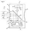
- FIG. 2 shows a further embodiment of the security scanner according to the invention 10.
- the same reference numerals designate the same features.
- the cylindrical shape of the windshield 38 is slightly concave. As a result, for example, dust accumulates unevenly. For example, when mounted vertically, area 40b will become more contaminated than area 40a.
- the front screen 38 in a structured manner, that is to say provide, for example, uncoated subregions provided with an anti-fingerprint coating. As a rule, a completely homogeneous contamination is avoided with these measures.
- FIG. 3 shows a further embodiment of the security scanner 10, in which an area 40a of the front screen 38 has a different inclination than another area 40b.
- the inclination may be less than shown in order to deviate as little as possible from the space-saving cylindrical shape. Due to the different local inclination of the two windscreen areas 40a-b to the optical axis of the receiving path, a remitted light beam 22a has to pass through a seemingly thicker soiling layer due to the shallower angle of incidence. As a result, a completely homogeneous contamination is detected.
- both homogeneous and inhomogeneous contaminants are reliably detected.
- Manipulations such as a partial covering of the windscreen 38 are detected.
Landscapes
- Engineering & Computer Science (AREA)
- Physics & Mathematics (AREA)
- Computer Networks & Wireless Communication (AREA)
- General Physics & Mathematics (AREA)
- Radar, Positioning & Navigation (AREA)
- Remote Sensing (AREA)
- Electromagnetism (AREA)
- Optical Radar Systems And Details Thereof (AREA)
Claims (15)
- Scanner laser de sécurité (10) pour la protection d'une zone surveillée (20) avec un émetteur de lumière (12) pour émettre un faisceau lumineux (16), un dispositif de déviation (18) pour dévier périodiquement le faisceau lumineux (16) dans la zone surveillée (20), un récepteur de lumière (26) pour générer un signal de réception à partir d'un faisceau lumineux (22) remis par des objets dans la zone surveillée (20), et une optique de réception (24) arrangée devant le récepteur de lumière (26), et le récepteur de lumière comprend plusieurs éléments de réception de lumière (26a-b) et l'optique de réception (24) comprend plusieurs éléments d'optique partiels (24a-b) pour guider respectivement une fraction (22a-b) du faisceau de lumière remis sur un élément de réception de lumière associé (26a-b) à un élément d'optique partiel (24a-b) et ainsi générer des multiples signaux de réception partielle, caractérisé en ce que les éléments de réception de lumière (26a-b) et les éléments d'optique partiels (24a-b) sont configurés de telle sorte que les fractions (22a-b) du faisceau lumineux remis traversent différentes domaines (40a-b) de la vitre avant (38), et en ce qu'une unité d'évaluation (32) du scanner de sécurité (10) est configurée pour générer des informations de position des objets dans la zone surveillée (20) d'un ou plusieurs signaux de réception partielle.
- Scanner laser de sécurité (10) selon la revendication 1, caractérisé en ce qu'une unité de surveillance de la contamination (32) pour la vitre avant (38) du scanner laser de sécurité (10) est configurée pour comparer les signaux de réception partielle entre eux et pour donner un signal de service lorsque les signaux de réception partielle sont différents l'un de l'autre ou lorsque le rapport entre les signaux de réception partielle diffère d'un ratio calibré initialement.
- Scanner laser de sécurité (10) selon la revendication 2, caractérisé en ce que la vitre avant (38) est essentiellement de forme cylindrique.
- Scanner laser de sécurité (10) selon la revendication 2 ou 3, caractérisé en ce que la vitre avant (38) comporté des déformations intentionnelles pour l'accumulation hétérogène de contamination, en particulier une ceinture circonférentielle ou des zones circonférentielles avec des inclinations différentes.
- Scanner laser de sécurité (10) selon l'une des revendications 2 à 4, caractérisé en ce que pour l'accumulation hétérogène de contamination, la vitre avant (38) est affichée différente dans les différentes zones partielles.
- Scanner laser de sécurité (10) selon l'une des revendications précédentes, caractérisé en ce que le récepteur de lumière comprend deux éléments de réception de lumière (26a-b) et l'optique de réception comprend deux éléments d'optiques partiels (24a-b), en particulier ayant identiques entre les propriétés optiques.
- Scanner laser de sécurité (10) selon l'une des revendications précédentes, caractérisé en ce qu'au moins un élément de pré-traitement du signal est fourni pour superposer un signal de réception partielle retardé et inversé d'un signal de réception bipolaire avec un autre signal de réception partielle.
- Scanner laser de sécurité (10) selon la revendication 7, caractérisé en ce que l'unité d'évaluation (32) est configurée pour générer des informations de position des objets dans la zone surveillée (20) par le signal de réception bipolaire.
- Scanner laser de sécurité (10) selon l'une des revendications précédentes, caractérisé en ce qu'une sortie de sécurité (34) est fournie, et en ce que l'unité d'évaluation (32) est configurée pour émettre un signal d'arrêt via la sortie de sécurité (34) lors de la détection d'une intrusion interdite dans une zone protégée pré-déterminable dans la zone surveillée (20).
- Procédé pour la protection d'une zone surveillée (20) avec un scanner laser de sécurité (10) dans lequel un faisceau de lumière (16) est transmis qui scanne la zone surveillée (20) par le biais d'une déviation périodiques, et dans lequel un signal de réception est généré à partir du faisceau lumineux remis (22) par les objets dans la zone surveillée (20), et une fraction (22a-b) du faisceau de lumière remis est guidée d'un des multiples éléments respectifs de réception de lumière (26a-b) par une optique de réception partagée avec plusieurs éléments optiques partiels (24a-b) afin de générer des multiples signaux de réception partielle, caractérisé en ce que des informations de position des objets dans la zone surveillée (20) sont générées à partir d'un ou plusieurs signaux de réception partielle, et en ce que les fractions (22a-b) du faisceau de lumière remis traversent des différentes zones (40a-b) de la vitre avant (38).
- Procédé selon la revendication 10, caractérisé en ce que pour la surveillance de la contamination d'une vitre avant (38) du scanner laser de sécurité (10) ou pour la détection des manipulations de la vitre avant (38), les signaux de réception partielle sont comparés entre eux et un signal de service sera émis lorsque les signaux de réception partielle sont différents l'un de l'autre ou lorsque le rapport entre les signaux de réception partielle diffère d'un ratio calibré initialement.
- Procédé selon la revendication 10 ou 11, caractérisé en ce que deux signaux de réception partielle sont générés par des moyens de réception optiques qui ont deux éléments optiques partielle (24a-b).
- Procédé selon la revendication 12, caractérisé en ce que l'un des signaux de réception partielle est superposé retardé et est inversé avec l'autre signal de réception partielle.
- Procédé selon la revendication 13, caractérisé en ce que des informations des positions des objets dans la zone surveillée (20) sont générées au moyen du signal bipolaire de réception.
- Procédé selon l'une des revendications 10 à 14, caractérisé en ce qu'un signal d'arrêt est émis via une sortie de sécurité (34) lors de la détection interdite d'une intrusion dans une zone protégée pré-déterminable dans la zone surveillée (20).
Priority Applications (1)
| Application Number | Priority Date | Filing Date | Title |
|---|---|---|---|
| EP10159384A EP2375264B1 (fr) | 2010-04-08 | 2010-04-08 | Scanner de sécurité avec surveillance d'encrassement |
Applications Claiming Priority (1)
| Application Number | Priority Date | Filing Date | Title |
|---|---|---|---|
| EP10159384A EP2375264B1 (fr) | 2010-04-08 | 2010-04-08 | Scanner de sécurité avec surveillance d'encrassement |
Publications (2)
| Publication Number | Publication Date |
|---|---|
| EP2375264A1 EP2375264A1 (fr) | 2011-10-12 |
| EP2375264B1 true EP2375264B1 (fr) | 2012-05-30 |
Family
ID=42751813
Family Applications (1)
| Application Number | Title | Priority Date | Filing Date |
|---|---|---|---|
| EP10159384A Active EP2375264B1 (fr) | 2010-04-08 | 2010-04-08 | Scanner de sécurité avec surveillance d'encrassement |
Country Status (1)
| Country | Link |
|---|---|
| EP (1) | EP2375264B1 (fr) |
Cited By (5)
| Publication number | Priority date | Publication date | Assignee | Title |
|---|---|---|---|---|
| CN106458538A (zh) * | 2014-03-28 | 2017-02-22 | 科尼全球公司 | 光学测量装置、负载搬运设备、用于保护光学测量装置的方法以及用于更新负载搬运设备的方法 |
| US9964437B2 (en) | 2016-05-03 | 2018-05-08 | Datalogic IP Tech, S.r.l. | Laser scanner with reduced internal optical reflection comprising a light detector disposed between an interference filter and a collecting mirror |
| US10048120B2 (en) | 2016-05-03 | 2018-08-14 | Datalogic IP Tech, S.r.l. | Laser scanner and optical system |
| US10061021B2 (en) | 2016-07-06 | 2018-08-28 | Datalogic IP Tech, S.r.l. | Clutter filter configuration for safety laser scanner |
| US11585905B2 (en) | 2016-05-03 | 2023-02-21 | Datalogic Ip Tech S.R.L. | Laser scanner |
Families Citing this family (2)
| Publication number | Priority date | Publication date | Assignee | Title |
|---|---|---|---|---|
| EP3948345B1 (fr) * | 2019-03-29 | 2025-05-07 | OMRON Corporation | Indicateurs visuels pour systèmes de détection de présence |
| DE102020203191A1 (de) | 2020-03-12 | 2021-09-16 | Continental Automotive Gmbh | Empfängeranordnung für eine Sensoreinrichtung |
Family Cites Families (4)
| Publication number | Priority date | Publication date | Assignee | Title |
|---|---|---|---|---|
| DE4345448C2 (de) | 1992-12-08 | 1998-07-30 | Sick Ag | Laserabstandsermittlungsvorrichtung |
| DE4340756C5 (de) * | 1992-12-08 | 2006-08-10 | Sick Ag | Laserabstandsermittlungsvorrichtung |
| DE19707418C2 (de) | 1997-02-25 | 1999-06-24 | Leuze Electronic Gmbh & Co | Optoelektronische Vorrichtung |
| AT412029B (de) | 2002-01-16 | 2004-08-26 | Riegl Laser Measurement Sys | Verfahren zur aufnahme eines objektraumes |
-
2010
- 2010-04-08 EP EP10159384A patent/EP2375264B1/fr active Active
Cited By (5)
| Publication number | Priority date | Publication date | Assignee | Title |
|---|---|---|---|---|
| CN106458538A (zh) * | 2014-03-28 | 2017-02-22 | 科尼全球公司 | 光学测量装置、负载搬运设备、用于保护光学测量装置的方法以及用于更新负载搬运设备的方法 |
| US9964437B2 (en) | 2016-05-03 | 2018-05-08 | Datalogic IP Tech, S.r.l. | Laser scanner with reduced internal optical reflection comprising a light detector disposed between an interference filter and a collecting mirror |
| US10048120B2 (en) | 2016-05-03 | 2018-08-14 | Datalogic IP Tech, S.r.l. | Laser scanner and optical system |
| US11585905B2 (en) | 2016-05-03 | 2023-02-21 | Datalogic Ip Tech S.R.L. | Laser scanner |
| US10061021B2 (en) | 2016-07-06 | 2018-08-28 | Datalogic IP Tech, S.r.l. | Clutter filter configuration for safety laser scanner |
Also Published As
| Publication number | Publication date |
|---|---|
| EP2375264A1 (fr) | 2011-10-12 |
Similar Documents
| Publication | Publication Date | Title |
|---|---|---|
| EP3078985B1 (fr) | Capteur optoelectronique et procede de surveillance de transmission d'un disque frontal | |
| EP2375264B1 (fr) | Scanner de sécurité avec surveillance d'encrassement | |
| DE102012102395B3 (de) | Optoelektronischer Sensor und Verfahren zum Testen der Lichtdurchlässigkeit einer Frontscheibe | |
| EP2378309B1 (fr) | Capteur optoélectronique et procédé de production d'informations sur des objets dans une zone de surveillance | |
| EP2124069B1 (fr) | Système LIDAR omnidirectionnel | |
| EP2482094B1 (fr) | Capteur optoélectronique mesurant l'éloignement et procédé de détection d'objet | |
| EP2645125B1 (fr) | Laser scanner et procédé destiné à la détection d'objets dans une zone de surveillance | |
| EP3862780B1 (fr) | Balayeur laser de sécurité et procédé de surveillance de vitre frontale | |
| EP3699638B1 (fr) | Capteur optoélectronique et procédé de détection d'un objet | |
| EP3078984B1 (fr) | Capteur optoelectronique et procede de detection d'objets dans une zone de surveillance | |
| DE102011000863A1 (de) | Optoelektronischer Sensor und Verfahren zur Erfassung von Objekten | |
| EP2381268B1 (fr) | Scanner laser de sécurité | |
| EP3367135B1 (fr) | Capteur optique | |
| EP2375266B1 (fr) | Capteur optoélectronique et procédé de sécurisation | |
| DE102014115260B3 (de) | Sicherheitssystem zur Absicherung der Umgebung eines Objekts | |
| EP3859379A1 (fr) | Capteur optoélectronique avec filtre de réception adapté à l'angle de vue et procédé de détection des objets | |
| EP3671264A1 (fr) | Capteur et procédé de détection d'un objet | |
| EP4105682B1 (fr) | Capteur optoélectronique et procédé de détection des objets | |
| EP3578867B1 (fr) | Système de détecteurs pourvu de détecteurs de distance optoélectroniques | |
| EP3415951B1 (fr) | Capteur optique | |
| EP2508914B1 (fr) | Dispositif de détection optique | |
| EP3699637A1 (fr) | Capteur optoélectronique et procédé de détection d'un objet | |
| DE202012101007U1 (de) | Optoelektronischer Sensor | |
| EP3367129B1 (fr) | Capteur optoélectronique et procédé de détection d'objets | |
| EP4254001B1 (fr) | Détection d'objets dans une zone de surveillance |
Legal Events
| Date | Code | Title | Description |
|---|---|---|---|
| PUAI | Public reference made under article 153(3) epc to a published international application that has entered the european phase |
Free format text: ORIGINAL CODE: 0009012 |
|
| 17P | Request for examination filed |
Effective date: 20110103 |
|
| AK | Designated contracting states |
Kind code of ref document: A1 Designated state(s): AT BE BG CH CY CZ DE DK EE ES FI FR GB GR HR HU IE IS IT LI LT LU LV MC MK MT NL NO PL PT RO SE SI SK SM TR |
|
| AX | Request for extension of the european patent |
Extension state: AL BA ME RS |
|
| GRAP | Despatch of communication of intention to grant a patent |
Free format text: ORIGINAL CODE: EPIDOSNIGR1 |
|
| RIC1 | Information provided on ipc code assigned before grant |
Ipc: G01S 17/42 20060101ALI20111208BHEP Ipc: G01S 7/481 20060101AFI20111208BHEP Ipc: G01S 7/497 20060101ALI20111208BHEP Ipc: G01S 17/02 20060101ALI20111208BHEP Ipc: G01S 7/486 20060101ALI20111208BHEP |
|
| GRAS | Grant fee paid |
Free format text: ORIGINAL CODE: EPIDOSNIGR3 |
|
| GRAA | (expected) grant |
Free format text: ORIGINAL CODE: 0009210 |
|
| AK | Designated contracting states |
Kind code of ref document: B1 Designated state(s): AT BE BG CH CY CZ DE DK EE ES FI FR GB GR HR HU IE IS IT LI LT LU LV MC MK MT NL NO PL PT RO SE SI SK SM TR |
|
| REG | Reference to a national code |
Ref country code: GB Ref legal event code: FG4D Free format text: NOT ENGLISH |
|
| REG | Reference to a national code |
Ref country code: CH Ref legal event code: EP |
|
| REG | Reference to a national code |
Ref country code: AT Ref legal event code: REF Ref document number: 560305 Country of ref document: AT Kind code of ref document: T Effective date: 20120615 |
|
| REG | Reference to a national code |
Ref country code: IE Ref legal event code: FG4D Free format text: LANGUAGE OF EP DOCUMENT: GERMAN |
|
| REG | Reference to a national code |
Ref country code: DE Ref legal event code: R096 Ref document number: 502010000816 Country of ref document: DE Effective date: 20120726 |
|
| REG | Reference to a national code |
Ref country code: NL Ref legal event code: VDEP Effective date: 20120530 |
|
| REG | Reference to a national code |
Ref country code: LT Ref legal event code: MG4D Effective date: 20120530 |
|
| PG25 | Lapsed in a contracting state [announced via postgrant information from national office to epo] |
Ref country code: FI Free format text: LAPSE BECAUSE OF FAILURE TO SUBMIT A TRANSLATION OF THE DESCRIPTION OR TO PAY THE FEE WITHIN THE PRESCRIBED TIME-LIMIT Effective date: 20120530 Ref country code: SE Free format text: LAPSE BECAUSE OF FAILURE TO SUBMIT A TRANSLATION OF THE DESCRIPTION OR TO PAY THE FEE WITHIN THE PRESCRIBED TIME-LIMIT Effective date: 20120530 Ref country code: IS Free format text: LAPSE BECAUSE OF FAILURE TO SUBMIT A TRANSLATION OF THE DESCRIPTION OR TO PAY THE FEE WITHIN THE PRESCRIBED TIME-LIMIT Effective date: 20120930 Ref country code: CY Free format text: LAPSE BECAUSE OF FAILURE TO SUBMIT A TRANSLATION OF THE DESCRIPTION OR TO PAY THE FEE WITHIN THE PRESCRIBED TIME-LIMIT Effective date: 20120530 Ref country code: LT Free format text: LAPSE BECAUSE OF FAILURE TO SUBMIT A TRANSLATION OF THE DESCRIPTION OR TO PAY THE FEE WITHIN THE PRESCRIBED TIME-LIMIT Effective date: 20120530 Ref country code: NO Free format text: LAPSE BECAUSE OF FAILURE TO SUBMIT A TRANSLATION OF THE DESCRIPTION OR TO PAY THE FEE WITHIN THE PRESCRIBED TIME-LIMIT Effective date: 20120830 |
|
| PG25 | Lapsed in a contracting state [announced via postgrant information from national office to epo] |
Ref country code: GR Free format text: LAPSE BECAUSE OF FAILURE TO SUBMIT A TRANSLATION OF THE DESCRIPTION OR TO PAY THE FEE WITHIN THE PRESCRIBED TIME-LIMIT Effective date: 20120831 Ref country code: HR Free format text: LAPSE BECAUSE OF FAILURE TO SUBMIT A TRANSLATION OF THE DESCRIPTION OR TO PAY THE FEE WITHIN THE PRESCRIBED TIME-LIMIT Effective date: 20120530 Ref country code: SI Free format text: LAPSE BECAUSE OF FAILURE TO SUBMIT A TRANSLATION OF THE DESCRIPTION OR TO PAY THE FEE WITHIN THE PRESCRIBED TIME-LIMIT Effective date: 20120530 Ref country code: LV Free format text: LAPSE BECAUSE OF FAILURE TO SUBMIT A TRANSLATION OF THE DESCRIPTION OR TO PAY THE FEE WITHIN THE PRESCRIBED TIME-LIMIT Effective date: 20120530 |
|
| PG25 | Lapsed in a contracting state [announced via postgrant information from national office to epo] |
Ref country code: CZ Free format text: LAPSE BECAUSE OF FAILURE TO SUBMIT A TRANSLATION OF THE DESCRIPTION OR TO PAY THE FEE WITHIN THE PRESCRIBED TIME-LIMIT Effective date: 20120530 Ref country code: RO Free format text: LAPSE BECAUSE OF FAILURE TO SUBMIT A TRANSLATION OF THE DESCRIPTION OR TO PAY THE FEE WITHIN THE PRESCRIBED TIME-LIMIT Effective date: 20120530 Ref country code: SK Free format text: LAPSE BECAUSE OF FAILURE TO SUBMIT A TRANSLATION OF THE DESCRIPTION OR TO PAY THE FEE WITHIN THE PRESCRIBED TIME-LIMIT Effective date: 20120530 Ref country code: DK Free format text: LAPSE BECAUSE OF FAILURE TO SUBMIT A TRANSLATION OF THE DESCRIPTION OR TO PAY THE FEE WITHIN THE PRESCRIBED TIME-LIMIT Effective date: 20120530 Ref country code: EE Free format text: LAPSE BECAUSE OF FAILURE TO SUBMIT A TRANSLATION OF THE DESCRIPTION OR TO PAY THE FEE WITHIN THE PRESCRIBED TIME-LIMIT Effective date: 20120530 Ref country code: NL Free format text: LAPSE BECAUSE OF FAILURE TO SUBMIT A TRANSLATION OF THE DESCRIPTION OR TO PAY THE FEE WITHIN THE PRESCRIBED TIME-LIMIT Effective date: 20120530 |
|
| PG25 | Lapsed in a contracting state [announced via postgrant information from national office to epo] |
Ref country code: PT Free format text: LAPSE BECAUSE OF FAILURE TO SUBMIT A TRANSLATION OF THE DESCRIPTION OR TO PAY THE FEE WITHIN THE PRESCRIBED TIME-LIMIT Effective date: 20121001 Ref country code: IT Free format text: LAPSE BECAUSE OF FAILURE TO SUBMIT A TRANSLATION OF THE DESCRIPTION OR TO PAY THE FEE WITHIN THE PRESCRIBED TIME-LIMIT Effective date: 20120530 Ref country code: PL Free format text: LAPSE BECAUSE OF FAILURE TO SUBMIT A TRANSLATION OF THE DESCRIPTION OR TO PAY THE FEE WITHIN THE PRESCRIBED TIME-LIMIT Effective date: 20120530 |
|
| PLBE | No opposition filed within time limit |
Free format text: ORIGINAL CODE: 0009261 |
|
| STAA | Information on the status of an ep patent application or granted ep patent |
Free format text: STATUS: NO OPPOSITION FILED WITHIN TIME LIMIT |
|
| 26N | No opposition filed |
Effective date: 20130301 |
|
| REG | Reference to a national code |
Ref country code: DE Ref legal event code: R097 Ref document number: 502010000816 Country of ref document: DE Effective date: 20130301 |
|
| PG25 | Lapsed in a contracting state [announced via postgrant information from national office to epo] |
Ref country code: BG Free format text: LAPSE BECAUSE OF FAILURE TO SUBMIT A TRANSLATION OF THE DESCRIPTION OR TO PAY THE FEE WITHIN THE PRESCRIBED TIME-LIMIT Effective date: 20120830 |
|
| BERE | Be: lapsed |
Owner name: SICK A.G. Effective date: 20130430 |
|
| PG25 | Lapsed in a contracting state [announced via postgrant information from national office to epo] |
Ref country code: ES Free format text: LAPSE BECAUSE OF FAILURE TO SUBMIT A TRANSLATION OF THE DESCRIPTION OR TO PAY THE FEE WITHIN THE PRESCRIBED TIME-LIMIT Effective date: 20120910 |
|
| PG25 | Lapsed in a contracting state [announced via postgrant information from national office to epo] |
Ref country code: MC Free format text: LAPSE BECAUSE OF FAILURE TO SUBMIT A TRANSLATION OF THE DESCRIPTION OR TO PAY THE FEE WITHIN THE PRESCRIBED TIME-LIMIT Effective date: 20120530 |
|
| REG | Reference to a national code |
Ref country code: IE Ref legal event code: MM4A |
|
| PG25 | Lapsed in a contracting state [announced via postgrant information from national office to epo] |
Ref country code: BE Free format text: LAPSE BECAUSE OF NON-PAYMENT OF DUE FEES Effective date: 20130430 |
|
| PG25 | Lapsed in a contracting state [announced via postgrant information from national office to epo] |
Ref country code: IE Free format text: LAPSE BECAUSE OF NON-PAYMENT OF DUE FEES Effective date: 20130408 |
|
| PG25 | Lapsed in a contracting state [announced via postgrant information from national office to epo] |
Ref country code: MT Free format text: LAPSE BECAUSE OF FAILURE TO SUBMIT A TRANSLATION OF THE DESCRIPTION OR TO PAY THE FEE WITHIN THE PRESCRIBED TIME-LIMIT Effective date: 20120530 |
|
| PG25 | Lapsed in a contracting state [announced via postgrant information from national office to epo] |
Ref country code: SM Free format text: LAPSE BECAUSE OF FAILURE TO SUBMIT A TRANSLATION OF THE DESCRIPTION OR TO PAY THE FEE WITHIN THE PRESCRIBED TIME-LIMIT Effective date: 20120530 |
|
| PG25 | Lapsed in a contracting state [announced via postgrant information from national office to epo] |
Ref country code: TR Free format text: LAPSE BECAUSE OF FAILURE TO SUBMIT A TRANSLATION OF THE DESCRIPTION OR TO PAY THE FEE WITHIN THE PRESCRIBED TIME-LIMIT Effective date: 20120530 |
|
| PG25 | Lapsed in a contracting state [announced via postgrant information from national office to epo] |
Ref country code: HU Free format text: LAPSE BECAUSE OF FAILURE TO SUBMIT A TRANSLATION OF THE DESCRIPTION OR TO PAY THE FEE WITHIN THE PRESCRIBED TIME-LIMIT; INVALID AB INITIO Effective date: 20100408 Ref country code: LU Free format text: LAPSE BECAUSE OF NON-PAYMENT OF DUE FEES Effective date: 20130408 Ref country code: MK Free format text: LAPSE BECAUSE OF FAILURE TO SUBMIT A TRANSLATION OF THE DESCRIPTION OR TO PAY THE FEE WITHIN THE PRESCRIBED TIME-LIMIT Effective date: 20120530 |
|
| REG | Reference to a national code |
Ref country code: FR Ref legal event code: PLFP Year of fee payment: 7 |
|
| REG | Reference to a national code |
Ref country code: AT Ref legal event code: MM01 Ref document number: 560305 Country of ref document: AT Kind code of ref document: T Effective date: 20150408 |
|
| PG25 | Lapsed in a contracting state [announced via postgrant information from national office to epo] |
Ref country code: AT Free format text: LAPSE BECAUSE OF NON-PAYMENT OF DUE FEES Effective date: 20150408 |
|
| REG | Reference to a national code |
Ref country code: FR Ref legal event code: PLFP Year of fee payment: 8 |
|
| REG | Reference to a national code |
Ref country code: FR Ref legal event code: PLFP Year of fee payment: 9 |
|
| PGFP | Annual fee paid to national office [announced via postgrant information from national office to epo] |
Ref country code: CH Payment date: 20180424 Year of fee payment: 9 |
|
| PGFP | Annual fee paid to national office [announced via postgrant information from national office to epo] |
Ref country code: FR Payment date: 20180424 Year of fee payment: 9 |
|
| PGFP | Annual fee paid to national office [announced via postgrant information from national office to epo] |
Ref country code: GB Payment date: 20180424 Year of fee payment: 9 |
|
| REG | Reference to a national code |
Ref country code: CH Ref legal event code: PL |
|
| GBPC | Gb: european patent ceased through non-payment of renewal fee |
Effective date: 20190408 |
|
| PG25 | Lapsed in a contracting state [announced via postgrant information from national office to epo] |
Ref country code: LI Free format text: LAPSE BECAUSE OF NON-PAYMENT OF DUE FEES Effective date: 20190430 Ref country code: CH Free format text: LAPSE BECAUSE OF NON-PAYMENT OF DUE FEES Effective date: 20190430 Ref country code: GB Free format text: LAPSE BECAUSE OF NON-PAYMENT OF DUE FEES Effective date: 20190408 |
|
| PG25 | Lapsed in a contracting state [announced via postgrant information from national office to epo] |
Ref country code: FR Free format text: LAPSE BECAUSE OF NON-PAYMENT OF DUE FEES Effective date: 20190430 |
|
| PGFP | Annual fee paid to national office [announced via postgrant information from national office to epo] |
Ref country code: DE Payment date: 20250417 Year of fee payment: 16 |