EP4528997A1 - Moteur - Google Patents
Moteur Download PDFInfo
- Publication number
- EP4528997A1 EP4528997A1 EP23807805.9A EP23807805A EP4528997A1 EP 4528997 A1 EP4528997 A1 EP 4528997A1 EP 23807805 A EP23807805 A EP 23807805A EP 4528997 A1 EP4528997 A1 EP 4528997A1
- Authority
- EP
- European Patent Office
- Prior art keywords
- disposed
- rotor
- magnet
- sensor
- bearing
- Prior art date
- Legal status (The legal status is an assumption and is not a legal conclusion. Google has not performed a legal analysis and makes no representation as to the accuracy of the status listed.)
- Pending
Links
Images




Classifications
-
- H—ELECTRICITY
- H02—GENERATION; CONVERSION OR DISTRIBUTION OF ELECTRIC POWER
- H02K—DYNAMO-ELECTRIC MACHINES
- H02K1/00—Details of the magnetic circuit
- H02K1/06—Details of the magnetic circuit characterised by the shape, form or construction
- H02K1/22—Rotating parts of the magnetic circuit
- H02K1/27—Rotor cores with permanent magnets
- H02K1/2706—Inner rotors
- H02K1/272—Inner rotors the magnetisation axis of the magnets being perpendicular to the rotor axis
- H02K1/274—Inner rotors the magnetisation axis of the magnets being perpendicular to the rotor axis the rotor consisting of two or more circumferentially positioned magnets
- H02K1/2753—Inner rotors the magnetisation axis of the magnets being perpendicular to the rotor axis the rotor consisting of two or more circumferentially positioned magnets the rotor consisting of magnets or groups of magnets arranged with alternating polarity
- H02K1/278—Surface mounted magnets; Inset magnets
-
- H—ELECTRICITY
- H02—GENERATION; CONVERSION OR DISTRIBUTION OF ELECTRIC POWER
- H02K—DYNAMO-ELECTRIC MACHINES
- H02K11/00—Structural association of dynamo-electric machines with electric components or with devices for shielding, monitoring or protection
- H02K11/20—Structural association of dynamo-electric machines with electric components or with devices for shielding, monitoring or protection for measuring, monitoring, testing, protecting or switching
- H02K11/21—Devices for sensing speed or position, or actuated thereby
- H02K11/215—Magnetic effect devices, e.g. Hall-effect or magneto-resistive elements
-
- H—ELECTRICITY
- H02—GENERATION; CONVERSION OR DISTRIBUTION OF ELECTRIC POWER
- H02K—DYNAMO-ELECTRIC MACHINES
- H02K1/00—Details of the magnetic circuit
- H02K1/06—Details of the magnetic circuit characterised by the shape, form or construction
- H02K1/22—Rotating parts of the magnetic circuit
- H02K1/28—Means for mounting or fastening rotating magnetic parts on to, or to, the rotor structures
-
- H—ELECTRICITY
- H02—GENERATION; CONVERSION OR DISTRIBUTION OF ELECTRIC POWER
- H02K—DYNAMO-ELECTRIC MACHINES
- H02K21/00—Synchronous motors having permanent magnets; Synchronous generators having permanent magnets
- H02K21/12—Synchronous motors having permanent magnets; Synchronous generators having permanent magnets with stationary armatures and rotating magnets
- H02K21/14—Synchronous motors having permanent magnets; Synchronous generators having permanent magnets with stationary armatures and rotating magnets with magnets rotating within the armatures
- H02K21/16—Synchronous motors having permanent magnets; Synchronous generators having permanent magnets with stationary armatures and rotating magnets with magnets rotating within the armatures having annular armature cores with salient poles
-
- H—ELECTRICITY
- H02—GENERATION; CONVERSION OR DISTRIBUTION OF ELECTRIC POWER
- H02K—DYNAMO-ELECTRIC MACHINES
- H02K5/00—Casings; Enclosures; Supports
- H02K5/04—Casings or enclosures characterised by the shape, form or construction thereof
- H02K5/16—Means for supporting bearings, e.g. insulating supports or means for fitting bearings in the bearing-shields
- H02K5/163—Means for supporting bearings, e.g. insulating supports or means for fitting bearings in the bearing-shields radially supporting the rotary shaft at only one end of the rotor
-
- H—ELECTRICITY
- H02—GENERATION; CONVERSION OR DISTRIBUTION OF ELECTRIC POWER
- H02K—DYNAMO-ELECTRIC MACHINES
- H02K7/00—Arrangements for handling mechanical energy structurally associated with dynamo-electric machines, e.g. structural association with mechanical driving motors or auxiliary dynamo-electric machines
- H02K7/08—Structural association with bearings
- H02K7/085—Structural association with bearings radially supporting the rotary shaft at only one end of the rotor
-
- H—ELECTRICITY
- H02—GENERATION; CONVERSION OR DISTRIBUTION OF ELECTRIC POWER
- H02K—DYNAMO-ELECTRIC MACHINES
- H02K2213/00—Specific aspects, not otherwise provided for and not covered by codes H02K2201/00 - H02K2211/00
- H02K2213/03—Machines characterised by numerical values, ranges, mathematical expressions or similar information
Definitions
- the present embodiment relates to a motor.
- a motor is a device that converts an electrical energy into a rotational energy by using the force a conductor receives in a magnetic field.
- motors have expanded, the role of motors has become more important.
- the demand for motors being applied to steering systems, braking systems, and design systems is increasing significantly.
- the motor includes a housing, a stator being disposed inside the housing, and a rotor being disposed inside the stator, and is a device that generates rotational motion by electromagnetic interaction between the stator and the rotor. Specifically, a coil is wound on the stator, and a magnet facing the coil is disposed on the rotor, so that the rotor can rotate by the action of the coil and magnet.
- the motor includes a sensor magnet and a sensor to detect the rotational position of the rotor or rotation shaft.
- a sensor magnet is disposed on one surface of the rotor, and a sensor is disposed in a housing facing the sensor magnet, and the sensor detects the magnetic field of the sensor magnet to detect the position of the rotor or shaft.
- the present embodiment is intended to provide a motor that can be miniaturized by improving its structure.
- a motor comprises: a housing; a stator being disposed inside the housing; a rotor being disposed inside the stator; a shaft being coupled to the center of the rotor; and a sensor magnet being disposed outside the shaft, wherein a groove in which the sensor magnet is disposed is formed on one surface of the rotor.
- It may include a bearing being disposed to face one surface of the rotor and supporting the rotation of the shaft.
- the rotor includes a rotor core and a magnet being disposed on an outer surface of the rotor core, wherein the groove may be formed on one surface of the rotor core facing the bearing.
- the length between the sensor magnet and the bearing may be longer than the length between the rotor core and the bearing.
- At least a portion of the rotor core may be disposed to be overlapped with the sensor magnet.
- the length of the groove may be 1/2 or less than the length of the rotor core.
- the sensor magnet includes one surface facing the bearing and the other surface facing the one surface, wherein the other surface of the magnet may be in contact with the bottom surface of the groove.
- It includes a sensor plate in which the shaft is coupled to the center thereof and the sensor magnet is disposed on one surface facing the bearing, wherein the sensor plate may be disposed inside the groove.
- the sensor plate includes: a first region being disposed outside the shaft; and a second region being extended outward in a radial direction from one end of the first region and perpendicular to the first region, wherein the sensor magnet may be disposed on a surface of the second region.
- the surface of the second region facing the bearing and the surface of the sensor magnet may form the same plane.
- the length in an axial direction of a motor can be reduced by forming an arrangement region of a sensor magnet through a groove of a rotor core, there is an advantage that enables miniaturization of a motor.
- first, second, A, B, (a), and (b) may be used.
- a component when a component is described as being 'connected', 'coupled' or 'interconnected' to another component, the component is not only directly connected, coupled or interconnected to the other component, but may also include cases of being 'connected', 'coupled', or 'interconnected' due that another component between that other components.
- the 'axial direction' used hereinafter may be a lengthwise direction of the shaft.
- the 'radial direction' used hereinafter may be a direction perpendicular to the 'axial direction'.
- FIG. 1 is a perspective view illustrating an outer appearance of a motor according to an embodiment of the present invention
- FIG. 2 is a cross-sectional view of a motor according to an embodiment of the present invention
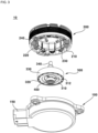
- FIG. 3 is an exploded perspective view of a motor according to an embodiment of the present invention
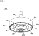
- FIG. 4 is a perspective view of a rotor according to an embodiment of the present invention
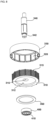
- FIG. 5 is an exploded perspective view of a rotor according to an embodiment of the present invention
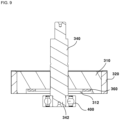
- FIG. 6 is a cross-sectional view of a rotor according to an embodiment of the present invention
- FIGS. 7 to 9 are diagrams illustrating a modified embodiment of a rotor and a sensor magnet according to an embodiment of the present invention.
- the motor 10 may comprise a housing 100, a stator 200, a rotor 300, a shaft 340, and a bearing 400.
- the housing 100 may form an outer shape of the motor 10.
- the housing 100 may have a cylindrical shape with an open upper surface.
- a space 110 for accommodating the stator 200, the rotor 300, and the shaft 340 may be formed inside the housing 100.
- An upper surface of the space 110 may be opened upward.
- a cover (not shown) may be coupled to an upper surface of the housing 100.
- the space 110 may be closed by the coupling of the cover.
- the connector terminal 190 may be formed on a side surface of the housing 100.
- the connector terminal 190 may have a shape being protruded outward from the other region of an outer surface of the housing 100.
- a space to which an external terminal (not shown) is coupled may be formed inside the connector terminal 190.
- a pin 192 being electrically connected to the external terminal may be disposed inside the connector terminal 190. Power may be provided to the motor 10 by electrical connection between the external terminal and the pin 192, or an electric signal related to driving of the motor 10 may be transmitted or received.
- the stator 200 may be disposed inside the housing 10.
- the stator 200 may include a stator core 210, an insulator 220, and a coil 230.
- the stator core 210 may include a circular body and a plurality of teeth being protruded inward from an inner surface of the body.
- the plurality of teeth may be disposed to be spaced apart from one another along a circumferential direction.
- the insulator 220 may be coupled to an outer surface of the stator core 210.
- the insulator 220 may be disposed to surround an outer surface of the stator core 210.
- the coil 230 may be wound around an outer surface of the insulator 220.
- a bus bar 240 may be disposed on one surface of the stator core 210.
- the coil 230 may be coupled to the bus bar 240.
- a plurality of bus bars 240 may be provided to correspond to the polarity of the coil 230 and may be disposed to be spaced apart from one another along a circumferential direction.
- the rotor 300 may be disposed inside the stator 200.
- the rotor 300 may include a rotor core 310, a magnet 320, and a cover plate 330.
- the rotor core 310 may have a circular cross-sectional shape.
- a hole 316 to which the shaft 340 is coupled may be formed in the center of the rotor core 310.
- a magnet coupling part 315, to which the magnet 320 is coupled, may be formed on an outer surface of the rotor core 310.
- the magnet coupling part 315 may have a groove shape being recessed inwardly than other regions.
- a plurality of magnet coupling parts 315 may be provided and may be disposed to be spaced apart from one another along a circumferential direction. Accordingly, a region between two magnet coupling parts 315 being disposed adjacent to each other may have a shape being protruded outward.
- the magnet 320 may be coupled to an outer surface of the rotor core 310.
- the magnet 320 may be disposed to face the coil 230.
- the magnet 320 may be mounted on an outer circumferential surface of the rotor core 310.
- the magnet 320 may be coupled to the magnet coupling part 315.
- the magnet 320 may be coupled to the rotor core 310 by an adhesive.
- the adhesive may be disposed between an inner surface of the magnet 320 and a bottom surface of the magnet coupling part 315.
- a plurality of magnets 320 may be provided and disposed to be spaced apart from one another along a circumferential direction of the rotor core 310.
- An outer surface of the magnet 320 may be protruded outward from an outer surface of the rotor core 310 with respect to a radial direction.
- the cover plate 330 may be disposed outside the rotor core 310.
- the cover plate 330 may have a ring-shaped cross-sectional shape.
- the cover plate 330 may be disposed to cover the outer surface of the magnet 320 and the outer surface of the rotor core 310.
- An adhesive may be disposed between the inner surface of the cover plate 330 and the outer surface of the magnet 320, and between the inner surface of the cover plate 330 and the outer surface of the rotor core 310.
- the length of the cover plate 330 may correspond to the length of the magnet 320 or the length of the rotor core 310.
- the shaft 340 may be coupled to the center of the rotor 300.
- the shaft 340 may be disposed to penetrate the hole 316 formed at the center of the rotor core 310. Therefore, the shaft 340 may rotate together with the rotor 300 by the electromagnetic interaction between the magnet 320 and the coil 230.
- the rotor 300 may include a plurality of regions having different cross-sectional areas.
- a bearing coupling part 342 being formed to have a cross-sectional area smaller than that of the other region may be disposed at one end of the rotor 300.
- a bearing 400 may be disposed in a region being spaced apart from the rotor 300 by a predetermined distance in an axial direction.
- the bearing 400 may support rotation of the rotor 300 and the shaft 340.
- the bearing 400 may be disposed in a space inside the housing 100.
- the bearing 400 may be a ball bearing having a ball being disposed between an inner wheel and an outer wheel.
- a hole 410 to which the shaft 340 is coupled may be formed at the center of the bearing 400.
- a bearing coupling part 342 of the shaft 340 may be coupled to the hole 410. Accordingly, the rotation of the shaft 340 may be supported through the bearing 400.
- the bearing 400 and the rotor 300 may be disposed to be spaced apart from each other by a predetermined distance along an axial direction.
- an interval between the bearing 400 and the rotor core 310 may be 1 mm or more and 3 mm or less with respect to the axial direction.
- the motor 10 may include a sensor magnet 360 and a sensor (not shown).
- a groove 312 being formed to be recessed more than the other region may be formed on one surface of the rotor core 310 facing the bearing 400.
- the bottom surface of the groove 312 may be disposed to be stepped upward than a lower surface of the rotor core 310.
- the groove 312 may have a circular cross-sectional shape.
- the cross-sectional area of the groove 312 may be formed to be smaller than the cross-sectional area of the rotor core 310.
- the length of the groove 312 may be equal to or less than 1/2 of the length of the rotor core 310 with respect to an axial direction.
- the sensor magnet 360 may be disposed in the groove 312.
- the sensor magnet 360 may be coupled to the shaft 340 and the rotor core 320 through a sensor plate 370.
- the sensor plate 370 may include a first region 377 being disposed to surround an outer surface of the shaft 340, and a second region 375 being bent radially outward and extended from one end of the first region 377.
- the first region 377 and the second region 375 may be disposed to be perpendicular to each other.
- a hole 372 through which the shaft 340 penetrates may be formed at the center of the first region 377.
- the shaft 340 may be press-fitted into the hole 372, and accordingly, the shaft 340 may be disposed to penetrate the sensor plate 370.
- One end of the first region 377 may be in contact with a bottom surface of the groove 312.
- the second region 375 may be formed to be extended radially outward from a lower end of the first region 377.
- the second region 375 may be disposed perpendicular to the shaft 340.
- the second region 375 may include an opening 371 penetrating from one surface to the other surface.
- the opening 371 may be disposed outside the hole 372.
- a plurality of openings 371 may be provided and may be disposed to be spaced apart from one another along a circumferential direction of the second region 375.
- three openings 371 may be provided, and the three openings 371 may be disposed to form an equal interval of 120 degrees.
- a coupling force between the sensor magnet 360 and the sensor plate 370 may be identified through the opening 371.
- a sensor magnet coupling part 378 having a shape being recessed more than the other region may be formed on one surface of the second region 375 facing the bearing 400.
- the sensor magnet coupling part 378 may have a groove shape.
- the bottom surface of the sensor magnet coupling part 378 may be disposed to be stepped more upward than the bottom surface of the second region 375.
- the sensor magnet 360 may be disposed on the sensor magnet coupling part 378.
- the sensor magnet 360 may have a cross-sectional shape of a ring shape.
- One surface of the sensor magnet 360 may form a coplanar surface with one surface of the second region 375.
- the bottom surface of the sensor magnet 360 may form a coplanar surface with the bottom surface of the second region 375.
- the sensor magnet 360 may be coupled to the sensor plate 370 by an adhesive.
- the sensor magnet 360 may be spaced apart from the bottom surface of the groove 312 by a predetermined distance.
- the sensor magnet 360 may rotate with the shaft 340 together with the sensor plate 370.
- a sensor may be disposed inside the housing 100 being spaced apart from the sensor magnet 360.
- the sensor may be disposed at a lower portion of the housing 100 being spaced apart from the sensor magnet 360 in an axial direction.
- the sensor may be disposed on a surface of a printed circuit board (not shown), and may detect positions of the rotor 300 and the shaft 340 by detecting a magnetic field being changed according to rotation of the sensor magnet 360.
- the sensor plate 370 and the sensor magnet 360 may be disposed inside the groove 312 of the rotor core 310. Accordingly, the length between the sensor plate 370 and the bearing 400 may be formed to be longer with respect to the axial direction. The length between the sensor magnet 360 and the bearing 400 may be formed to be longer than the length between the rotor core 310 and the bearing 400. A lower surface of the sensor plate 370 or a lower surface of the sensor magnet 360 may be disposed to be stepped more upward than a lower surface of the rotor core 310. The sensor plate 370 and the sensor magnet 360 may be disposed to be overlapped with the magnet 320 in a radial direction. The sensor plate 370 and the sensor magnet 360 may be disposed to be overlapped with the rotor core 310 in a radial direction.
- the length of the motor 10 can be reduced with respect to an axial direction by forming an arrangement region of the sensor magnet 360 through the groove 312 of the rotor core 310, so that there is an advantage that the motor 10 can be miniaturized.
- the sensor plate 370 may be omitted from the motor 10. In this case, only the sensor magnet 360 can be disposed in the groove 312 of the rotor core 310.
- the axial length of the groove 312 can be formed shorter than in the above-described embodiment.
- an upper surface of the sensor magnet 360 may be in contact with the bottom surface of the groove 312. In this case, the upper surface of the sensor magnet 360 may be coupled to the bottom surface of the groove 312 with an adhesive.
Landscapes
- Engineering & Computer Science (AREA)
- Power Engineering (AREA)
- Microelectronics & Electronic Packaging (AREA)
Applications Claiming Priority (2)
| Application Number | Priority Date | Filing Date | Title |
|---|---|---|---|
| KR1020220060539A KR20230161028A (ko) | 2022-05-18 | 2022-05-18 | 모터 |
| PCT/KR2023/005616 WO2023224282A1 (fr) | 2022-05-18 | 2023-04-25 | Moteur |
Publications (2)
| Publication Number | Publication Date |
|---|---|
| EP4528997A1 true EP4528997A1 (fr) | 2025-03-26 |
| EP4528997A4 EP4528997A4 (fr) | 2026-04-29 |
Family
ID=88835552
Family Applications (1)
| Application Number | Title | Priority Date | Filing Date |
|---|---|---|---|
| EP23807805.9A Pending EP4528997A4 (fr) | 2022-05-18 | 2023-04-25 | Moteur |
Country Status (5)
| Country | Link |
|---|---|
| US (1) | US20250286443A1 (fr) |
| EP (1) | EP4528997A4 (fr) |
| KR (1) | KR20230161028A (fr) |
| CN (1) | CN119234377A (fr) |
| WO (1) | WO2023224282A1 (fr) |
Family Cites Families (6)
| Publication number | Priority date | Publication date | Assignee | Title |
|---|---|---|---|---|
| JP3939862B2 (ja) * | 1998-08-18 | 2007-07-04 | ヤマハ発動機株式会社 | 電動自転車用モータ駆動ユニット |
| KR200191099Y1 (ko) * | 2000-02-29 | 2000-08-16 | 삼성광주전자주식회사 | 스위치드 릴럭턴스 모터의 센싱구조 |
| KR101108308B1 (ko) * | 2010-03-29 | 2012-01-25 | 엘지이노텍 주식회사 | 트랙션 모터 모듈 |
| KR101799104B1 (ko) * | 2010-12-27 | 2017-12-20 | 엘지이노텍 주식회사 | 모터 |
| KR101604889B1 (ko) | 2013-04-01 | 2016-03-21 | 뉴모텍(주) | 센서 마그넷을 갖는 모터 |
| KR102493906B1 (ko) * | 2017-11-02 | 2023-01-31 | 엘지이노텍 주식회사 | 모터 |
-
2022
- 2022-05-18 KR KR1020220060539A patent/KR20230161028A/ko active Pending
-
2023
- 2023-04-25 US US18/859,297 patent/US20250286443A1/en active Pending
- 2023-04-25 CN CN202380040270.2A patent/CN119234377A/zh active Pending
- 2023-04-25 WO PCT/KR2023/005616 patent/WO2023224282A1/fr not_active Ceased
- 2023-04-25 EP EP23807805.9A patent/EP4528997A4/fr active Pending
Also Published As
| Publication number | Publication date |
|---|---|
| CN119234377A (zh) | 2024-12-31 |
| US20250286443A1 (en) | 2025-09-11 |
| WO2023224282A1 (fr) | 2023-11-23 |
| EP4528997A4 (fr) | 2026-04-29 |
| KR20230161028A (ko) | 2023-11-27 |
Similar Documents
| Publication | Publication Date | Title |
|---|---|---|
| US10651704B2 (en) | Rotating device | |
| CN114123672B (zh) | 无刷马达 | |
| KR102547570B1 (ko) | 모터 | |
| US11527940B2 (en) | Motor | |
| US12323035B2 (en) | Motor | |
| KR20180009237A (ko) | 모터 | |
| EP1703622B1 (fr) | Moteur asynchrone hybride | |
| US8796891B2 (en) | Brushless DC motor | |
| US11799351B2 (en) | Motor | |
| EP4528997A1 (fr) | Moteur | |
| US12237748B2 (en) | Motor having shield terminal | |
| US12101014B2 (en) | Rotary electric motor | |
| US12088172B2 (en) | Motor | |
| CN113169629B (zh) | 电机 | |
| JP2009112139A (ja) | ブラシレスモータ | |
| US20240322621A1 (en) | Motor | |
| KR102655249B1 (ko) | 모터 및 이를 포함하는 전동식 조향장치 | |
| JP2013074725A (ja) | レゾルバステータ構造 | |
| CN118176646A (zh) | 电机 | |
| EP4307539A1 (fr) | Moteur | |
| KR20180092423A (ko) | 모터 | |
| CN109301947B (zh) | 定子和具有定子的马达 | |
| KR20180049727A (ko) | 차량용 교류 발전기의 슬립링 및 이를 포함하는 차량용 교류 발전기 | |
| KR20160004547A (ko) | 모터 | |
| KR20240007024A (ko) | 모터 |
Legal Events
| Date | Code | Title | Description |
|---|---|---|---|
| STAA | Information on the status of an ep patent application or granted ep patent |
Free format text: STATUS: THE INTERNATIONAL PUBLICATION HAS BEEN MADE |
|
| PUAI | Public reference made under article 153(3) epc to a published international application that has entered the european phase |
Free format text: ORIGINAL CODE: 0009012 |
|
| STAA | Information on the status of an ep patent application or granted ep patent |
Free format text: STATUS: REQUEST FOR EXAMINATION WAS MADE |
|
| 17P | Request for examination filed |
Effective date: 20241118 |
|
| AK | Designated contracting states |
Kind code of ref document: A1 Designated state(s): AL AT BE BG CH CY CZ DE DK EE ES FI FR GB GR HR HU IE IS IT LI LT LU LV MC ME MK MT NL NO PL PT RO RS SE SI SK SM TR |
|
| DAV | Request for validation of the european patent (deleted) | ||
| DAX | Request for extension of the european patent (deleted) |