EP4529807A2 - Brosse pour une brosse à dents sonique à vibration longitudinale - Google Patents
Brosse pour une brosse à dents sonique à vibration longitudinale Download PDFInfo
- Publication number
- EP4529807A2 EP4529807A2 EP25157733.4A EP25157733A EP4529807A2 EP 4529807 A2 EP4529807 A2 EP 4529807A2 EP 25157733 A EP25157733 A EP 25157733A EP 4529807 A2 EP4529807 A2 EP 4529807A2
- Authority
- EP
- European Patent Office
- Prior art keywords
- brush
- longitudinal axis
- head
- base body
- geometric
- Prior art date
- Legal status (The legal status is an assumption and is not a legal conclusion. Google has not performed a legal analysis and makes no representation as to the accuracy of the status listed.)
- Pending
Links
Images

Classifications
-
- A—HUMAN NECESSITIES
- A46—BRUSHWARE
- A46B—BRUSHES
- A46B9/00—Arrangements of the bristles in the brush body
- A46B9/02—Position or arrangement of bristles in relation to surface of the brush body, e.g. inclined, in rows, in groups
- A46B9/04—Arranged like in or for toothbrushes
Definitions
- the invention relates to a brush for a sonic toothbrush with longitudinal axis vibration, comprising an elongated base body which: has a truncated cone-shaped base part with a drive adapter for rotationally fixed coupling to a sonic toothbrush drive with longitudinal axis vibration; a head part with a bristle carrier in which a plurality of bristles are anchored; and which has an elongated neck part which connects the base part and the head part.
- the handset has a coupling pin that rotates back and forth around its longitudinal axis.
- the brush which is attached to the coupling pin, has a straight neck and, at the end, a bristle plate, the bristles of which are perpendicular to the longitudinal axis of the handset or the brush neck.
- the advantage of this geometry is that relatively low forces (moments) occur because the mass (neck, bristle plate) of the brush attachment is relatively close to the longitudinal axis (center of movement). The intensity of movement is also relatively evenly distributed across the bristle area.
- WO 2017/050612 A1 is a sonic toothbrush with an angled brush head. Because the sonic toothbrush is angled forward, different parts of the teeth are more easily accessible. The bend also ensures that the brush filaments oscillate with a greater amplitude perpendicular to the brush's longitudinal axis.
- the preferred operating frequency is 2000 to 8000 Hertz. However, the frequencies can also be higher, for example, 10 kHz, 50 kHz, or even lower, for example, 200 Hz or 500 Hz.
- An ultrasonic toothbrush that has two parallel channels running perpendicular to the brush's longitudinal axis to increase the resonant frequency.
- the frequency increases in a forward-backward direction when the two channels are positioned at the front. If the channels are positioned on the left and right sides of the brush neck, the frequency increases in a lateral direction.
- the object of the invention is to create a toothbrush for sonic toothbrushes belonging to the aforementioned technical field, which has an improved cleaning effect, particularly one that is gentle on the gums.
- a defined and controlled two-dimensional movement of the bristles is to be generated.
- the solution is defined by claim 1.
- the base body has a bending angle such that a geometric foot part longitudinal axis and a geometric head part alignment axis enclose an angle ⁇ in the range of 5° to 12°. Furthermore, a geometric bending position in the base body has a distance from an end surface of the foot part of at least 50% of the total length of the base body.
- the sonic toothbrush according to the invention essentially generates an oscillation of the brush around its longitudinal axis, i.e., the longitudinal axis of the base (defined here as the x-axis).
- the bristles therefore primarily perform a wiping motion transverse to the aforementioned longitudinal axis.
- a particular advantage of the brush according to the invention is that it has a bending angle position that results in a sufficiently large deflection (also called eccentricity) of the head section, so that a certain oscillation also occurs in the direction of the longitudinal axis.
- the result is a two-dimensional movement that can be described as a "figure-8" movement. This is particularly advantageous in several respects.
- one advantage of this brush design is that the brush also performs a slight "nod” motion toward the bristles. This pushes the mixture of saliva and toothpaste "forward” into the interdental spaces. This is especially important for single-tuft toothbrushes, which are specifically designed for better interdental cleaning.
- the bristle carrier has several tufts, each with a plurality of bristles.
- the bristle carrier has exactly one tuft with a plurality of bristles (single-tuft variant).
- the bristles can also be indirectly anchored to the surface of the bristle carrier, especially if the brush is designed as an interdental brush.
- the bristle carrier has a twisted or folded wire loop on its surface, with the bristles clamped between the strands.
- the head alignment axis is preferably oriented perpendicular to the wire alignment.
- the geometric bending position is defined by an intersection point between the geometric foot part longitudinal axis and the geometric head part alignment axis. Therefore, the geometric bending position does not necessarily require a bend-like (or knee-like) change in the direction of the base body. Preferably, the geometric bending position is located within the base body.
- the shape of the base body does not necessarily have to include a visually recognizable bend, but can, for example, be arc-shaped. In variants, the geometric bending position can also be located outside the base body. Further variations are known to those skilled in the art.
- the distance between the end face of the foot section and the bending position is measured along the foot section's longitudinal axis.
- the total length of the base body is also measured along the foot section's longitudinal axis.
- the geometric bending position has a relatively large distance from the head part in order to achieve, in conjunction with the angle ⁇ (gamma) between the geometric foot part longitudinal axis and the geometric head part alignment axis of 5° to 12°, a particularly optimal vibration behavior for cleaning the teeth.
- ⁇ gamma
- the eccentricity increases when the bending position is further away from the head part.
- the distance between the geometric bending position and the end surface of the foot section is preferably at least 60% of the total length of the base body. This defines a particularly optimal range for the geometric bending position, which, according to experiments, leads to particularly advantageous 2-dimensional or 3-dimensional vibration patterns. This allows for particularly effective yet gentle tooth cleaning.
- the distance of the geometric bending position to the end surface of the foot part can also be between 50% and 60% of the total length of the base body.
- the distance between the geometric bending position and the end surface of the foot section is a maximum of 75% of the total length (L) of the base body.
- the inventive bending angle of 5° to 12° allows for a sufficiently strong "8" movement, allowing for considerable design flexibility regarding the geometric dimensions of the neck section and head section.
- the head section is plate-shaped and the neck section is rod-shaped.
- the head section in cross-section (i.e., in the plane perpendicular to the head section alignment axis), the head section is wider in one direction (e.g., the y-direction) than in the other direction (e.g., the z-direction).
- the shape of the cross-section can be, for example, rectangular, trapezoidal, or oval.
- the neck section may be circular, oval, square, hexagonal, octagonal, trapezoidal, or a geometric approximation or modification of such a shape.
- the cross-sectional shape need not be rotationally symmetrical.
- the head part is at least about twice as wide as the neck part.
- the head section is at most approximately 1.5 times as long as the neck section. This can also be combined with the previously mentioned embodiment.
- the head portion in a cross-section spanned by the longitudinal axis of the brush and the head alignment axis, is approximately the same thickness as the neck portion. If the head portion is plate-shaped, then the neck portion is approximately the same thickness as the head portion plate.
- the head portion is at least about twice as wide and at most about 1.5 times as long as the neck portion. Particularly preferably, the head portion is between 2 and 3 times as wide and preferably between 0.5 and 1.5 times as long as the neck portion.
- the relatively slender neck portion, compared to the head portion, achieves particularly good vibration behavior and thus optimal tooth cleaning.
- the head part can also be less than twice as wide and more than 1.5 times as long as the neck part.
- the head portion has a mass that is greater than the mass of the neck portion; in particular, the head portion has a mass that is preferably more than 30%, particularly preferably more than 50%, greater than the mass of the neck portion.
- This mass distribution can be achieved either by appropriate geometric dimensions or by different materials, or by both.
- the relatively large mass of the head compared to the neck allows for a slight nodding motion of the brush head (a movement in the z-direction) to be optimized during toothbrush operation.
- the larger mass increases the momentum of the nodding motion, which can amplify the two-dimensional "8" movement and, in turn, better reach the interdental spaces. This is particularly, but not only, a great advantage with the single-tuft variant or the interdental brush.
- the head section can also have a mass that is less than 30% greater than the mass of the neck section; in particular, the masses of the head section and the neck section can also be approximately the same. This is the case, for example, if the head section is the same thickness as the neck section, and if the neck section is three times as long as the head section, and the head section is three times as wide as the neck section.
- the foot section is approximately the same length as the head section. This ensures that the foot section is sufficiently large to ensure a stable attachment to the sonic toothbrush drive (e.g., with a long adapter channel for a correspondingly long handset pin). The vibration and thus the kinetic energy of the drive are efficiently transferred to the head section via the neck section.
- the foot section is shorter than the head section; in particular, the foot section is approximately half the length of the head section. This creates more design freedom for the neck section. If, in such a design, the drive adapter is also designed as a slender pin on the brush that inserts into an adapter channel in the handset, the stable attachment to the sonic toothbrush drive is concealed.
- the foot section can also be longer than the head section.
- the neck section has a transverse dimension that is no more than one-quarter of the length of the neck section.
- the transverse dimension is defined as a diameter perpendicular to the geometric alignment axis or perpendicular to the foot section's longitudinal axis.
- the head section's alignment axis is decisive
- the foot section's longitudinal axis is decisive.
- the neck section is thus deliberately kept slim to support the head section's vibration behavior, particularly the in-plane vibration behavior (the "8" movement) and the pitching movement.
- the transverse dimension can also be more than a quarter of the length of the neck piece. This can be useful, for example, if a particularly flexible or elastic material is used for the neck piece.
- the base body is made of a load-bearing material with a Young's modulus of less than 8,000 MPa.
- the Young's modulus is in the range of 2,000 MPa to 6,000 MPa. This results in a base body that is sufficiently elastic to optimally transmit vibrations while also being sufficiently stable.
- the modulus of elasticity is at least 2500 MPa, in particular at least 3000 MPa. This ensures a base body that is sufficiently strong to optimally transmit the longitudinal axis vibrations.
- the modulus of elasticity can tend to be lower (e.g. 2000 MPa to 3000 MPa) than at large bending angles (e.g. at 15°).
- Another special design is characterized by the fact that the modulus of elasticity of the supporting material (or materials) of the base body is in the range of 4000 MPa to 6000 MPa.
- an elastic modulus in the range of 5000 MPa to 6000 MPa is advantageous.
- the base body consists essentially of a single piece made of a single material. This allows for particularly cost-effective production of the base body. It also enables particularly optimal vibration behavior, since no boundary transitions between different materials disrupt the vibration behavior, particularly 2-dimensional or 3-dimensional vibration behavior, in which such a boundary transition is bent in different directions by the vibration pattern.
- a one-piece base body made of a supporting material is also referred to when the surface of the brush is covered by a non-supporting Material coated or coated.
- areas of the base section can be made of a material with increased roughness or surface grip, making it easier to remove the brush from the drive pin with your fingers.
- the base body is essentially formed by two material parts joined together.
- a very rigid plastic with a high modulus of elasticity
- the neck can be designed to be sufficiently elastic using a less rigid material (the modulus of elasticity of the neck part material is lower than the modulus of elasticity of the base part).
- the base body is essentially formed by three material-bonded parts.
- the base body can consist of two material-bonded parts of different strengths in the longitudinal direction.
- the head section, neck section, and foot section can be made of different materials. The requirements for the head section are different from those for the foot section, which can be optimized by selecting the right material.
- a base body made of two or three materially bonded materials is produced, for example, by modern plastic injection molding processes with two or three materials.
- Non-load-bearing (e.g. soft) coating layers may also be present on the base body with the two or three load-bearing material parts in order to achieve certain functions (e.g. protection when the back of the brush comes into contact with the teeth).
- the head portion has a deflection of 10% - 20% relative to the length of the brush.
- Deflection is defined here as the ratio between the distance from the center (center of gravity) of the head portion to the adapter's longitudinal axis, divided by the total length L (in the x-direction) of the base body.
- the deflection can be considered the "eccentricity of the head portion with respect to the adapter's longitudinal axis.” is decisive for the vibration pattern: it was found that with a deflection of 10% - 20% the "8" movement is particularly pronounced.
- the deflection can also be less than 10% or greater than 20%.
- the deflection is preferably selected in the range of 20% to prevent the head from becoming too small.
- the deflection is preferably selected in the range of 10%, because at higher frequencies, the head's imbalance could otherwise become too large.
- the bristles protrude essentially perpendicularly from the brush's head section alignment axis.
- the angle between the foot section's longitudinal axis and the bristle direction is then 90° minus the bend angle ⁇ (gamma).
- ⁇ gamma
- the bristles are anchored, for example, to the main surface of the plate-shaped head.
- the head can also be rod-shaped, with the single tuft anchored in a cylindrical recess (e.g., a blind hole).
- a geometric base section longitudinal axis and a geometric head section alignment axis enclose an angle ⁇ (gamma) in the range of 7° to 10°.
- This angular range has proven particularly advantageous in experiments, allowing a particularly ideal vibration pattern to be achieved for tooth cleaning. Experiments have shown that the vibration pattern, in particular the "8" movement, is particularly advantageous, allowing tooth cleaning with the brush to be carried out particularly gently.
- the angular range has also proven particularly advantageous in conjunction with the deflection or eccentricity of the head section relative to the total length of the brush, between 10% and 20%, and has also led to particularly good cleaning results with optimal ergonomics.
- the neck section is tapered in cross-section compared to the head section. This means that the head section is wider and/or thicker (viewed perpendicular to the head section alignment axis) than the neck section. This makes the neck section mechanically less rigid than the head section (provided the base body is made of one or more materials with approximately the same modulus of elasticity).
- a sonic toothbrush with longitudinal axis vibration according to the invention comprises a brush according to the invention and a handset with a brush coupling for releasably attaching the brush to the handset and with a drive that generates a longitudinal axis vibration at the brush coupling.
- the drive can, for example, comprise a piezo drive, a magnetic drive, and/or an electric rotary drive.
- a piezo drive is particularly preferred, in particular due to its simple design, particularly compact construction, and precise controllability.
- the drive is preferably designed to generate a longitudinal axis oscillation frequency in the range of 150 Hz to 400 Hz. Since the brush generates a 2-dimensional or 3-dimensional movement pattern, the longitudinal axis oscillation frequency is set relatively low, allowing more time to execute multiple changes of direction per oscillation, e.g., in a figure-8 movement.
- the longitudinal axis oscillation frequency is advantageously no higher than 300 Hz. If the frequency is too high, the base body can no longer transmit the longitudinal axis oscillation generated by the drive to the brush head. This can lead to internal torsional movements, which can cause the head to, for example, only execute every other oscillation.
- the longitudinal axis vibration frequency can also be less than 150 Hz, e.g. 120 Hz.
- the drive is designed to generate a longitudinal axis oscillation with an amplitude (deflection relative to a rest position) of less than 3°, in particular in the range of 1° to 3°.
- amplitude deflection relative to a rest position
- the foot part is periodically rotated (moved back and forth) by the angle around the foot part's longitudinal axis.
- the amplitude can also be greater than 3°.
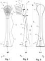
- the Figure 1 shows a schematic representation of a top view of a brush 10.
- the brush 10 comprises a truncated cone-shaped base part 11, a rod-shaped neck part 12, which adjoins the truncated cone-shaped base part 11, and finally a plate-shaped head part 13, which adjoins the neck part 12.
- the three parts form the base body of the brush.
- the truncated cone-shaped base part 11 comprises a drive adapter.
- this is essentially formed by a channel-shaped receptacle 14 into which a pin of the handset of the sonic toothbrush can be inserted and locked (see below for Figure 4 ).
- the brush 10 has a base part longitudinal axis 20, which is aligned coaxially with the receptacle 14 or, during operation of the sonic toothbrush, coaxially with the pin.
- This longitudinal axis defines the x-axis of the xyz coordinate system used here.
- the drive adapter defines the geometric base part longitudinal axis (x) of the brush.
- the bristle field 17 of the head part 13 is also visible, which in the present case has several (e.g. 20 - 40) tufts, each with a large number (e.g. 100 - 200) of bristles.
- the head section 13 is teardrop-shaped when viewed from the front. This means that its shape gradually widens – starting at the transition to the neck section – almost to the upper end of the head section, where it ends in a rounded final contour. With this shape (for a given length of the bristle field in the x-direction), the center of gravity of the head section 13 is closer to the end of the brush. This can enhance the eccentric effect at the specified operating frequency and thus also the "8" movement.
- the main surface of the plate-shaped head part 13 extends essentially transversely to the x-axis in the y-direction.
- FIG-8 On the bristle field 17, a figure-8 in the y-direction is also shown with reference numeral 23.
- the figure-8 illustrates the movement that is executed in the plane during operation due to the selected material property (Young's modulus), the angle between the geometric foot part longitudinal axis 20 and the geometric head part alignment axis (see below), and the bending position.
- the brush also performs a slight nodding motion with the head section 13—this movement is essentially perpendicular to the figure-8, i.e., essentially in the z-direction.
- the bristles are thus moved in three dimensions (x, y, z).
- the Figure 2 shows a schematic representation of a side view of the brush 10.
- the geometric foot part longitudinal axis 20 and the head part alignment axis 21 are arranged one behind the other.
- the head part alignment axis 21 is essentially the longitudinal axis of the head part.
- the two axes intersect at the geometric bending position 22.
- the geometric foot part longitudinal axis 20 and the geometric head part alignment axis 21 form an angle ⁇ (gamma) of 10°.
- the geometric bending position 22 is at a distance K from the end surface of the foot part 11 of 50% of the total length L of the brush 10. This combination of the angle to the bending position 22 creates a brush 10 with which particularly effective and gum-friendly cleaning of the teeth is possible.
- the head part 13 is plate-shaped and the neck part 12 is rod-shaped.
- the head part 13 and the neck part 12 have the same transverse dimension (i.e. the same thickness).
- the head section 13 is approximately three times as wide (y-direction) as the neck section 12.
- the length (x-direction) of the head section is approximately one-third greater than the width (y-direction).
- the neck section 11 is one-third as wide and 1.5 times as long as the head section 13.
- the neck part 12 is tapered compared to the head part 13 and the foot part 11.
- the neck part 12 is in at least one of the side views (here in the z-direction according to Figure 1 viewed) less wide than the headboard 13.
- the deflection is determined by the ratio of distance A to the length L of the brush.
- the distance A corresponds to the distance from the front center of the head section (which here corresponds to the center of the bristle field 17) to the foot section's longitudinal axis 20 (see Figure 2 ). In this example, the deflection is 14%.
- the bristles are arranged in several clusters and protrude vertically from the main surface of the plate-shaped head section. In this case, they are perpendicular to the y-direction and extend in the x-z plane. In the present embodiment, the bristles are attached to the front of the head section (or the front side 27 of the brush), i.e., they point slightly downward toward the adapter surface (y-z plane) of the base section.
- the Figure 3 shows a schematic representation of a back view of the brush 10 according to the Figures 1 and 2
- the base body has a different material on the back side 26, which is soft and provides protection (protective layer, protective coating) when the back of the brush comes into contact with the teeth.
- This material is non-load-bearing and can therefore have an elastic modulus outside the elastic modulus range of 2000-6000 MPa according to the invention.
- the load-bearing material is visible on the front side 27 and makes up a significant portion of the cross-section of the base body.
- the Figure 4 shows a schematic representation of a top view (z-direction) of a sonic toothbrush comprising the brush 10 and a handset 16 with a pin 15.
- the brush 10 is attached to the pin 15 so that the brush is detachable, rotationally fixed, and axially fixed.
- the handset 16 rotates the pin 15 back and forth at a frequency of e.g., 180 - 270 Hz with an amplitude of, for example, 2° (relative to a resting position) around the longitudinal axis of the pin 15 (which corresponds to the longitudinal axis of the handset 16).
- the brush thus rotates back and forth around the base's longitudinal axis 20 (x-axis).
- the Figure 5a shows a schematic representation of a side view of a sonic toothbrush 10.
- the sonic toothbrush 10 comprises a handset 16 and a brush 10.
- the drive of the handset 16 is designed as a piezoelectric drive (not shown), which generates an oscillation of the brush 10 about the x-axis 20 (longitudinal axis of the handset).
- the brush 10 executes a rotational oscillation about the x-axis 20 relative to the handle.
- This effect is controlled by the appropriately angled bend in the brush neck, the appropriately selected modulus of elasticity, and can be adjusted by other geometric design features of the brush (such as bend angle position, deflection, mass distribution, and other features according to the particular embodiments of the invention).
- the Figure 5b shows a schematic plan view of a personal care device according to Figure 5a .
- the Z-direction 25 is visible. It runs essentially in the direction of the bristles.
- the handset is significantly larger than the brush. Only in this way can it generate a longitudinal axis vibration (instead of an undefined or undirected vibration movement, as is the case with conventional sonic toothbrushes).
- the Figure 6 shows an embodiment of the sonic toothbrush, which comprises exactly one tuft 18.
- the tuft 18 is arranged at the rear of the head portion 13.
- the head portion is essentially tilted backward.
- the Figure 7 shows a schematic representation of the inventive "8" movement.
- the "8" movement has the shape of a one-sided flattened “8", with an axis of symmetry (X-axis) running through the center 27 of the "8".
- the two loops 28a, 28b of the "8" extend in the y-direction.
- the invention is not limited to exactly this shape of the "8" movement, the exact shape of the movement ultimately depends on the parameters of the brush head as well as the vibration generated by the handset motor.
- the Figure 8 illustrates the amplitude of the longitudinal axis oscillation movement.
- the x-axis is perpendicular to the plane of the drawing.
- the plate-shaped head part 13 (shown without bristles) pivots around the x-axis by the angle ⁇ (alpha).
- the bristles extend in Figure 8 (upward in the z-direction).
- the main component of the pivoting movement (and thus the bristle wiping movement) is in the y-direction.
- the angle ⁇ (alpha) is preferably 2°.
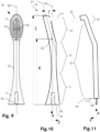
- the Figure 9 shows a brush 10 with a plate-shaped oval head 13.
- the longitudinal axis of the oval shape runs essentially in the x-direction and the transverse axis in the y-direction.
- the center of the head 13 is further away from the upper end of the brush 10 than in the drop-shaped head according to Figure 1 .
- Figure 10 shows a brush with a bending angle ⁇ (gamma) of 14° and a distance K of the geometric bending position 22 to the end surface 29 of the foot part 11 of 75% based on the length L of the brush.
- the base section 11 tapers from the end surface 29 to the transition into the neck section 12.
- the base section 11 can be, for example, truncated cone-shaped or truncated pyramid-shaped, with a concave profile in longitudinal section.
- the center of gravity of the base section 11 is closer to the end surface 29 than in a comparable base section with straight profile lines.
- the neck part 12 takes up approximately half the length (L) of the brush.
- the neck portion 12 does not necessarily have to have a constant cross-section along its entire length. It may well have a changing contour.
- the head part 13 is formed by the extension of the neck part 12.
- the head part 13 has substantially the same transverse dimensions (viewed in a section perpendicular to the head part alignment axis 21) as the neck part 12.
- the Bristle field 17 is placed laterally on the head part 13. The bristles thus protrude perpendicularly to the head part alignment axis 21.
- Figure 11 shows an embodiment in which the base part 11 is essentially formed by a pin 30 as a drive adapter.
- the neck part 12 is rod-shaped and takes up, for example, 90% of the brush length.
- the head part 13 is the part in which the bristle field 17, here in the form of a single tuft, is anchored.
- the pin 30 is inserted into the handset in the x-direction for rotationally fixed coupling to a sonic toothbrush drive with longitudinal axis oscillation, whereby the drive adapter defines the geometric base part longitudinal axis (x) of the brush.
- a brush according to Fig. 11 is made of a material with a Young's modulus of approximately 4600 MPa.
Landscapes
- Brushes (AREA)
Priority Applications (1)
| Application Number | Priority Date | Filing Date | Title |
|---|---|---|---|
| EP25157733.4A EP4529807A3 (fr) | 2021-09-14 | 2021-09-14 | Brosse pour une brosse à dents sonique à vibration longitudinale |
Applications Claiming Priority (2)
| Application Number | Priority Date | Filing Date | Title |
|---|---|---|---|
| EP21196660.1A EP4147604B1 (fr) | 2021-09-14 | 2021-09-14 | Brosse pour une brosse à dents sonique à oscillation axiale longitudinale |
| EP25157733.4A EP4529807A3 (fr) | 2021-09-14 | 2021-09-14 | Brosse pour une brosse à dents sonique à vibration longitudinale |
Related Parent Applications (2)
| Application Number | Title | Priority Date | Filing Date |
|---|---|---|---|
| EP21196660.1A Division EP4147604B1 (fr) | 2021-09-14 | 2021-09-14 | Brosse pour une brosse à dents sonique à oscillation axiale longitudinale |
| EP21196660.1A Previously-Filed-Application EP4147604B1 (fr) | 2021-09-14 | 2021-09-14 | Brosse pour une brosse à dents sonique à oscillation axiale longitudinale |
Publications (2)
| Publication Number | Publication Date |
|---|---|
| EP4529807A2 true EP4529807A2 (fr) | 2025-04-02 |
| EP4529807A3 EP4529807A3 (fr) | 2025-04-09 |
Family
ID=77774701
Family Applications (2)
| Application Number | Title | Priority Date | Filing Date |
|---|---|---|---|
| EP25157733.4A Pending EP4529807A3 (fr) | 2021-09-14 | 2021-09-14 | Brosse pour une brosse à dents sonique à vibration longitudinale |
| EP21196660.1A Active EP4147604B1 (fr) | 2021-09-14 | 2021-09-14 | Brosse pour une brosse à dents sonique à oscillation axiale longitudinale |
Family Applications After (1)
| Application Number | Title | Priority Date | Filing Date |
|---|---|---|---|
| EP21196660.1A Active EP4147604B1 (fr) | 2021-09-14 | 2021-09-14 | Brosse pour une brosse à dents sonique à oscillation axiale longitudinale |
Country Status (4)
| Country | Link |
|---|---|
| EP (2) | EP4529807A3 (fr) |
| HR (1) | HRP20250375T1 (fr) |
| PL (1) | PL4147604T3 (fr) |
| RS (1) | RS66671B1 (fr) |
Citations (12)
| Publication number | Priority date | Publication date | Assignee | Title |
|---|---|---|---|---|
| JPH0443127A (ja) | 1990-06-07 | 1992-02-13 | Mazda Motor Corp | 車両の動力伝達装置 |
| DE29913406U1 (de) | 1999-07-31 | 1999-11-25 | Rowenta-Werke GmbH, 63071 Offenbach | Zubehörträger für eine elektrische Zahnbürste |
| WO2005046508A1 (fr) | 2003-11-13 | 2005-05-26 | Trisa Holding Ag | Brosse a dents et procede pour sa production |
| US20060168744A1 (en) | 2005-01-28 | 2006-08-03 | Butler Clarence P | Electric toothbrush for implementing the bass brushing technique |
| EP2454967A1 (fr) | 2010-11-19 | 2012-05-23 | Braun GmbH | Outil de protection orale |
| JP2012161368A (ja) | 2011-02-03 | 2012-08-30 | Sanion:Kk | 口腔清掃用具用照明付振動器および口腔清掃用具 |
| WO2012151259A1 (fr) | 2011-05-02 | 2012-11-08 | Water Pik, Inc. | Brosse à dents sonique à entraînement mécanique |
| US20120291212A1 (en) | 2011-05-16 | 2012-11-22 | Montagnino James G | Resonant vibration-enhancing cleaning attachment for an ultrasonic powered handle |
| EP2548531A2 (fr) | 2006-09-29 | 2013-01-23 | Trisa Holding AG | Brosse à dents électrique et transmission pour une brosse à dents électrique |
| WO2013104020A1 (fr) | 2012-01-13 | 2013-07-18 | Erskine Products Pty Ltd | Article d'hygiène dentaire |
| WO2017050612A1 (fr) | 2015-09-22 | 2017-03-30 | Curaden Ag | Tête de brosse |
| DE102016011477A1 (de) | 2016-09-22 | 2018-03-22 | M + C Schiffer Gmbh | Bürstenkopf insbesondere für eine elektrisch angetriebene Zahnbürste und Verfahren zu deren Herstellung |
Family Cites Families (1)
| Publication number | Priority date | Publication date | Assignee | Title |
|---|---|---|---|---|
| JPS611738A (ja) | 1984-06-14 | 1986-01-07 | Kayaba Ind Co Ltd | 建設車両の合流回路 |
-
2021
- 2021-09-14 PL PL21196660.1T patent/PL4147604T3/pl unknown
- 2021-09-14 EP EP25157733.4A patent/EP4529807A3/fr active Pending
- 2021-09-14 RS RS20250318A patent/RS66671B1/sr unknown
- 2021-09-14 HR HRP20250375TT patent/HRP20250375T1/hr unknown
- 2021-09-14 EP EP21196660.1A patent/EP4147604B1/fr active Active
Patent Citations (13)
| Publication number | Priority date | Publication date | Assignee | Title |
|---|---|---|---|---|
| JPH0443127A (ja) | 1990-06-07 | 1992-02-13 | Mazda Motor Corp | 車両の動力伝達装置 |
| DE29913406U1 (de) | 1999-07-31 | 1999-11-25 | Rowenta-Werke GmbH, 63071 Offenbach | Zubehörträger für eine elektrische Zahnbürste |
| US6766548B1 (en) | 1999-07-31 | 2004-07-27 | Rowenta-Werke Gmbh | Accessories mount for an electric toothbrush |
| WO2005046508A1 (fr) | 2003-11-13 | 2005-05-26 | Trisa Holding Ag | Brosse a dents et procede pour sa production |
| US20060168744A1 (en) | 2005-01-28 | 2006-08-03 | Butler Clarence P | Electric toothbrush for implementing the bass brushing technique |
| EP2548531A2 (fr) | 2006-09-29 | 2013-01-23 | Trisa Holding AG | Brosse à dents électrique et transmission pour une brosse à dents électrique |
| EP2454967A1 (fr) | 2010-11-19 | 2012-05-23 | Braun GmbH | Outil de protection orale |
| JP2012161368A (ja) | 2011-02-03 | 2012-08-30 | Sanion:Kk | 口腔清掃用具用照明付振動器および口腔清掃用具 |
| WO2012151259A1 (fr) | 2011-05-02 | 2012-11-08 | Water Pik, Inc. | Brosse à dents sonique à entraînement mécanique |
| US20120291212A1 (en) | 2011-05-16 | 2012-11-22 | Montagnino James G | Resonant vibration-enhancing cleaning attachment for an ultrasonic powered handle |
| WO2013104020A1 (fr) | 2012-01-13 | 2013-07-18 | Erskine Products Pty Ltd | Article d'hygiène dentaire |
| WO2017050612A1 (fr) | 2015-09-22 | 2017-03-30 | Curaden Ag | Tête de brosse |
| DE102016011477A1 (de) | 2016-09-22 | 2018-03-22 | M + C Schiffer Gmbh | Bürstenkopf insbesondere für eine elektrisch angetriebene Zahnbürste und Verfahren zu deren Herstellung |
Also Published As
| Publication number | Publication date |
|---|---|
| HRP20250375T1 (hr) | 2025-06-06 |
| EP4147604B1 (fr) | 2025-02-19 |
| PL4147604T3 (pl) | 2025-04-28 |
| EP4147604C0 (fr) | 2025-02-19 |
| RS66671B1 (sr) | 2025-05-30 |
| EP4529807A3 (fr) | 2025-04-09 |
| EP4147604A1 (fr) | 2023-03-15 |
Similar Documents
| Publication | Publication Date | Title |
|---|---|---|
| EP1061829B1 (fr) | Brosse a dent et partie de brosse | |
| EP1912532B2 (fr) | Brosse a dents pourvue de poils inclines et tailles en pointe | |
| EP2886081B1 (fr) | Brosse à dents électrique dotée d'une tête de brosse | |
| DE69629062T3 (de) | Zahnbürste | |
| EP3352703B1 (fr) | Tête de brosse | |
| EP0689404A1 (fr) | Brosse a dents electrique | |
| WO2003073958A1 (fr) | Tete d'une brosse a dents electrique | |
| EP3413748A1 (fr) | Dispositif brosse ménager ou d'hygiène | |
| CH713325B1 (de) | Zahnbürste mit schräggestellten Borsten und zugespitzten Borsten. | |
| EP2184033A1 (fr) | Brosse à dents électrique et sa brosse | |
| DE69628347T2 (de) | Zahnbürste | |
| DE2728672A1 (de) | Zahnbuerste | |
| WO2023041603A1 (fr) | Brosse pour brosse à dents sonique à vibration d'axe longitudinal | |
| WO2006012974A1 (fr) | Brosse a dents electrique | |
| EP4147605B1 (fr) | Brosse pour une brosse à dents sonique à oscillation axiale longitudinale | |
| EP4147604B1 (fr) | Brosse pour une brosse à dents sonique à oscillation axiale longitudinale | |
| WO2020083554A1 (fr) | Instrument interdentaire | |
| WO2023041602A1 (fr) | Brosse pour brosse à dents sonique à vibration d'axe longitudinal | |
| DE10215805C1 (de) | Zahnreinigungsteil sowie Verfahren zur Herstellung eines solchen und Zahnreinigungsinstrument mit einem solchen | |
| DE202008012567U1 (de) | Handgerät mit Vibrationsantrieb | |
| DE3409543A1 (de) | Ultraschallgeraet, insbesondere ultraschallbetriebenes dentalgeraet | |
| DE1632390C3 (de) | Bürste für ein Zahnbehandlungsgerät | |
| WO2018002192A1 (fr) | Brosse | |
| DE202024100374U1 (de) | Elektrische Zahnbürste mit abgewinkeltem Bürstenkopf | |
| DE102005041459A1 (de) | Massagebürstenkopf zur Zahnfleischmassage und elektrische Zahnbürste mit einem solchen Massagebürstenkopf |
Legal Events
| Date | Code | Title | Description |
|---|---|---|---|
| PUAI | Public reference made under article 153(3) epc to a published international application that has entered the european phase |
Free format text: ORIGINAL CODE: 0009012 |
|
| STAA | Information on the status of an ep patent application or granted ep patent |
Free format text: STATUS: THE APPLICATION HAS BEEN PUBLISHED |
|
| PUAL | Search report despatched |
Free format text: ORIGINAL CODE: 0009013 |
|
| AC | Divisional application: reference to earlier application |
Ref document number: 4147604 Country of ref document: EP Kind code of ref document: P |
|
| AK | Designated contracting states |
Kind code of ref document: A2 Designated state(s): AL AT BE BG CH CY CZ DE DK EE ES FI FR GB GR HR HU IE IS IT LI LT LU LV MC MK MT NL NO PL PT RO RS SE SI SK SM TR |
|
| AK | Designated contracting states |
Kind code of ref document: A3 Designated state(s): AL AT BE BG CH CY CZ DE DK EE ES FI FR GB GR HR HU IE IS IT LI LT LU LV MC MK MT NL NO PL PT RO RS SE SI SK SM TR |
|
| RIC1 | Information provided on ipc code assigned before grant |
Ipc: A46B 9/04 20060101AFI20250304BHEP |
|
| STAA | Information on the status of an ep patent application or granted ep patent |
Free format text: STATUS: REQUEST FOR EXAMINATION WAS MADE |
|
| 17P | Request for examination filed |
Effective date: 20250930 |
|
| STAA | Information on the status of an ep patent application or granted ep patent |
Free format text: STATUS: EXAMINATION IS IN PROGRESS |
|
| 17Q | First examination report despatched |
Effective date: 20260225 |