EP4530120A2 - Dispositif de distribution de fluide d'un circuit de thermorégulation - Google Patents
Dispositif de distribution de fluide d'un circuit de thermorégulation Download PDFInfo
- Publication number
- EP4530120A2 EP4530120A2 EP24202892.6A EP24202892A EP4530120A2 EP 4530120 A2 EP4530120 A2 EP 4530120A2 EP 24202892 A EP24202892 A EP 24202892A EP 4530120 A2 EP4530120 A2 EP 4530120A2
- Authority
- EP
- European Patent Office
- Prior art keywords
- connector
- line
- connection
- supply line
- bearing section
- Prior art date
- Legal status (The legal status is an assumption and is not a legal conclusion. Google has not performed a legal analysis and makes no representation as to the accuracy of the status listed.)
- Pending
Links
Images


Classifications
-
- F—MECHANICAL ENGINEERING; LIGHTING; HEATING; WEAPONS; BLASTING
- F16—ENGINEERING ELEMENTS AND UNITS; GENERAL MEASURES FOR PRODUCING AND MAINTAINING EFFECTIVE FUNCTIONING OF MACHINES OR INSTALLATIONS; THERMAL INSULATION IN GENERAL
- F16L—PIPES; JOINTS OR FITTINGS FOR PIPES; SUPPORTS FOR PIPES, CABLES OR PROTECTIVE TUBING; MEANS FOR THERMAL INSULATION IN GENERAL
- F16L3/00—Supports for pipes, cables or protective tubing, e.g. hangers, holders, clamps, cleats, clips, brackets
- F16L3/22—Supports for pipes, cables or protective tubing, e.g. hangers, holders, clamps, cleats, clips, brackets specially adapted for supporting a number of parallel pipes at intervals
- F16L3/237—Supports for pipes, cables or protective tubing, e.g. hangers, holders, clamps, cleats, clips, brackets specially adapted for supporting a number of parallel pipes at intervals for two pipes
-
- B—PERFORMING OPERATIONS; TRANSPORTING
- B60—VEHICLES IN GENERAL
- B60L—PROPULSION OF ELECTRICALLY-PROPELLED VEHICLES; SUPPLYING ELECTRIC POWER FOR AUXILIARY EQUIPMENT OF ELECTRICALLY-PROPELLED VEHICLES; ELECTRODYNAMIC BRAKE SYSTEMS FOR VEHICLES IN GENERAL; MAGNETIC SUSPENSION OR LEVITATION FOR VEHICLES; MONITORING OPERATING VARIABLES OF ELECTRICALLY-PROPELLED VEHICLES; ELECTRIC SAFETY DEVICES FOR ELECTRICALLY-PROPELLED VEHICLES
- B60L50/00—Electric propulsion with power supplied within the vehicle
- B60L50/50—Electric propulsion with power supplied within the vehicle using propulsion power supplied by batteries or fuel cells
- B60L50/60—Electric propulsion with power supplied within the vehicle using propulsion power supplied by batteries or fuel cells using power supplied by batteries
- B60L50/64—Constructional details of batteries specially adapted for electric vehicles
-
- B—PERFORMING OPERATIONS; TRANSPORTING
- B60—VEHICLES IN GENERAL
- B60L—PROPULSION OF ELECTRICALLY-PROPELLED VEHICLES; SUPPLYING ELECTRIC POWER FOR AUXILIARY EQUIPMENT OF ELECTRICALLY-PROPELLED VEHICLES; ELECTRODYNAMIC BRAKE SYSTEMS FOR VEHICLES IN GENERAL; MAGNETIC SUSPENSION OR LEVITATION FOR VEHICLES; MONITORING OPERATING VARIABLES OF ELECTRICALLY-PROPELLED VEHICLES; ELECTRIC SAFETY DEVICES FOR ELECTRICALLY-PROPELLED VEHICLES
- B60L58/00—Methods or circuit arrangements for monitoring or controlling batteries or fuel cells, specially adapted for electric vehicles
- B60L58/10—Methods or circuit arrangements for monitoring or controlling batteries or fuel cells, specially adapted for electric vehicles for monitoring or controlling batteries
- B60L58/24—Methods or circuit arrangements for monitoring or controlling batteries or fuel cells, specially adapted for electric vehicles for monitoring or controlling batteries for controlling the temperature of batteries
- B60L58/26—Methods or circuit arrangements for monitoring or controlling batteries or fuel cells, specially adapted for electric vehicles for monitoring or controlling batteries for controlling the temperature of batteries by cooling
-
- F—MECHANICAL ENGINEERING; LIGHTING; HEATING; WEAPONS; BLASTING
- F16—ENGINEERING ELEMENTS AND UNITS; GENERAL MEASURES FOR PRODUCING AND MAINTAINING EFFECTIVE FUNCTIONING OF MACHINES OR INSTALLATIONS; THERMAL INSULATION IN GENERAL
- F16L—PIPES; JOINTS OR FITTINGS FOR PIPES; SUPPORTS FOR PIPES, CABLES OR PROTECTIVE TUBING; MEANS FOR THERMAL INSULATION IN GENERAL
- F16L3/00—Supports for pipes, cables or protective tubing, e.g. hangers, holders, clamps, cleats, clips, brackets
- F16L3/08—Supports for pipes, cables or protective tubing, e.g. hangers, holders, clamps, cleats, clips, brackets substantially surrounding the pipe, cable or protective tubing
- F16L3/12—Supports for pipes, cables or protective tubing, e.g. hangers, holders, clamps, cleats, clips, brackets substantially surrounding the pipe, cable or protective tubing comprising a member substantially surrounding the pipe, cable or protective tubing
- F16L3/13—Supports for pipes, cables or protective tubing, e.g. hangers, holders, clamps, cleats, clips, brackets substantially surrounding the pipe, cable or protective tubing comprising a member substantially surrounding the pipe, cable or protective tubing and engaging it by snap action
-
- H—ELECTRICITY
- H01—ELECTRIC ELEMENTS
- H01M—PROCESSES OR MEANS, e.g. BATTERIES, FOR THE DIRECT CONVERSION OF CHEMICAL ENERGY INTO ELECTRICAL ENERGY
- H01M10/00—Secondary cells; Manufacture thereof
- H01M10/60—Heating or cooling; Temperature control
- H01M10/61—Types of temperature control
- H01M10/613—Cooling or keeping cold
-
- H—ELECTRICITY
- H01—ELECTRIC ELEMENTS
- H01M—PROCESSES OR MEANS, e.g. BATTERIES, FOR THE DIRECT CONVERSION OF CHEMICAL ENERGY INTO ELECTRICAL ENERGY
- H01M10/00—Secondary cells; Manufacture thereof
- H01M10/60—Heating or cooling; Temperature control
- H01M10/65—Means for temperature control structurally associated with the cells
- H01M10/656—Means for temperature control structurally associated with the cells characterised by the type of heat-exchange fluid
- H01M10/6567—Liquids
- H01M10/6568—Liquids characterised by flow circuits, e.g. loops, located externally to the cells or cell casings
-
- H—ELECTRICITY
- H01—ELECTRIC ELEMENTS
- H01M—PROCESSES OR MEANS, e.g. BATTERIES, FOR THE DIRECT CONVERSION OF CHEMICAL ENERGY INTO ELECTRICAL ENERGY
- H01M10/00—Secondary cells; Manufacture thereof
- H01M10/60—Heating or cooling; Temperature control
- H01M10/62—Heating or cooling; Temperature control specially adapted for specific applications
- H01M10/625—Vehicles
-
- Y—GENERAL TAGGING OF NEW TECHNOLOGICAL DEVELOPMENTS; GENERAL TAGGING OF CROSS-SECTIONAL TECHNOLOGIES SPANNING OVER SEVERAL SECTIONS OF THE IPC; TECHNICAL SUBJECTS COVERED BY FORMER USPC CROSS-REFERENCE ART COLLECTIONS [XRACs] AND DIGESTS
- Y02—TECHNOLOGIES OR APPLICATIONS FOR MITIGATION OR ADAPTATION AGAINST CLIMATE CHANGE
- Y02E—REDUCTION OF GREENHOUSE GAS [GHG] EMISSIONS, RELATED TO ENERGY GENERATION, TRANSMISSION OR DISTRIBUTION
- Y02E60/00—Enabling technologies; Technologies with a potential or indirect contribution to GHG emissions mitigation
- Y02E60/10—Energy storage using batteries
Definitions
- the invention relates to a fluid distribution arrangement of a temperature control circuit for controlling the temperature of an electrical device.
- the electrical device is a battery, in particular a battery of an electric vehicle.
- the fluid distribution arrangement has at least one supply line and at least one return line running substantially parallel to the supply line.
- the supply line is fluidically connectable to a supply line
- the return line is fluidically connectable to a return line.
- the supply line and the return line are designed such that the supply line and the return line are fluidically connectable to the electrical device by means of the supply line and the return line.
- the invention relates to a connection connector and a connector holder for such a fluid distribution arrangement.
- Such fluid distribution assemblies are known, in particular, from battery temperature control in electric vehicles.
- the batteries can be heated, in particular at low ambient temperatures, and/or cooled, for example, at high ambient temperatures and/or under load, by means of the fluid distribution assemblies.
- a battery can be formed from one or more battery modules that are electrically interconnected. It is known that the individual battery modules are each fluidically temperature-controlled by fluidly connecting each battery module to the supply and return lines of the fluid distribution assemblies.
- the supply line and the return line are arranged close to each other and in particular directly above the battery in order to save installation space.
- the supply line or the return line has branch elements which are connected directly to the respective battery module.
- the known fluid distribution assemblies have the disadvantage that the supply line and the return line are arranged close to one another, so that the arrangement of the lines is relatively rigid and inflexible. Furthermore, the known fluid distribution assemblies have a great height, so that sufficient space must always be provided, especially above the batteries. Different arrangements of the respective lines, for example to adapt to specific installation conditions, are therefore not possible or only possible with great effort. In particular, the respective lines must be manufactured specifically for the respective installation conditions and cannot be adapted to different installation conditions, which makes the production and provision of fluid distribution assemblies for different installation conditions or applications very complex.
- the invention is based on the object of improving a fluid distribution arrangement from the prior art in such a way that it overcomes the known disadvantages and, in particular, is adaptable to different installation conditions.
- the supply line is connected by means of at least one supply line to a connection connector for fluidic connection to the electrical device
- the return line is connected by means of at least one discharge line to a further connection connector for fluidic connection to the electrical device
- the supply line and the return line are arranged at a distance from one another in such a way that the supply line and the discharge line and the respective connection connectors are arranged between the supply line and the return line.
- the embodiment according to the invention has the advantage that the fluid distribution arrangements can be designed flatter, in particular in combination with a battery connected to the fluid distribution arrangement.
- the supply line and the discharge line allow the supply line and the return line to be further separated from one another and in particular from the Fluid connections of the battery are arranged at a distance, so that adaptation to different installation conditions is possible.
- the flow line is fluidically connected to the supply line by means of a distributor.
- the return line is also advantageously fluidically connected to the discharge line by means of a distributor.
- the supply line and/or the return line has a plurality of distributor pieces, which are expediently arranged at equal and/or different distances from one another and are fluidically connected by pipe sections formed between the respective distributor pieces. It can also be provided that more than one supply line or discharge line can be connected or is connected to the respective distributor piece, wherein in particular a specific distributor piece can be connected or is connected either exclusively to supply lines or exclusively to discharge lines.
- This embodiment is particularly advantageous when, for example, the connections of two battery modules of a battery to be temperature-controlled are arranged close to one another.
- the distributor piece can have at least one connecting element, in particular a plurality of connecting elements, for fluidically plugging the supply line or the discharge line. It has proven particularly advantageous for the respective connecting element to be designed as a plug-in mandrel onto which the supply line or the discharge line is plugged. The plug-in mandrel provides particularly low-effort installation of the supply or discharge line to the distributor piece.
- the supply line and/or the discharge line comprise at least one corrugated pipe section with a corrugated pipe casing and at least two smooth pipe sections with a smooth pipe casing.
- the at least one corrugated pipe section is advantageously arranged between the smooth pipe sections.
- the smooth pipe sections provide advantageous rigidity to the supply or discharge line, especially in the area of connection points to the supply or return line or to the respective distributor pieces and the respective connection connectors.
- the corrugated pipe sections advantageously improve the flexibility of the supply or discharge line, so that the fluid distribution arrangement can be better adapted to different installation conditions.
- connection connector(s) comprises/comprising a device connection for connection to a male or female plug connection of the electrical device and a line connection for connection to the supply line or discharge line.
- connection connector in particular, as an angled connector, with the device connection and the cable connection being formed at an angle to each other.
- the angle is 90°.
- the angled connector design allows the fluid distribution assemblies to be designed flatter, particularly in combination with a battery connected to the fluid distribution assembly.
- connection connector is arranged in a locking manner in a connector receptacle of a connector holder.
- the connector holder expediently has a mounting means for fixing it to a positioning device.
- This embodiment advantageously allows the connector holders to be pre-assembled to the positioning device, thus simplifying assembly.
- the positioning device is particularly preferably formed on the electrical device itself.
- the positioning device and the mounting means can be mutually correspondingly designed, mutually screwable screw elements, in particular threaded bolts, through-holes and nuts or screws, through-holes and threaded holes.
- connection connector of the supply line and the connection connector of the discharge line are arranged together on the connector holder, each locking into a connector receptacle.
- the connector holder has two connector receptacles, one for each connection connector.
- Such a connector holder advantageously reduces the number of preferred assembly means and positioning devices, so that the cost of manufacture and assembly is reduced.
- the connector holder has more than two, in particular four, connector receptacles, so that, for example, two connection connectors of a supply line and two connection connectors of a discharge line are arranged together on the connector holder.
- the embodiment with four connector receptacles can be particularly advantageous if, for example, the connections of two battery modules of a battery to be temperature-controlled are arranged close to one another.
- the connector holder with at least one C-shaped connector receptacle with two radially elastic retaining arms.
- the retaining arms preferably grip a cylindrical bearing section of the connecting connector.
- the connector receptacle and the connecting connector are configured to correspond to one another in such a way that the connecting connector is blocked against displacement axially relative to a longitudinal axis of the cylindrical bearing section and is reversibly fixed in at least one installation position by means of a positive-locking force against rotation about the longitudinal axis of the cylindrical bearing section.
- the connecting connectors can be arranged in the connector holder with little effort, in particular without tools.
- this Design advantageous in a small installation space, which makes the use of tools difficult.
- connection connector in the bearing section and the holding arms of the connector receptacle have locking means that correspond to one another such that the connection connector can be fixed in the connector receptacle in a force-fitting manner in at least two installation positions rotated relative to one another about the longitudinal axis of the cylindrical bearing section.
- the different installation positions improve the adaptability of the fluid distributor arrangement to different installation conditions in that a specific connection direction of the respective supply or discharge line can be configured relative to the longitudinal axis of the cylindrical bearing section of the connection connector. This expediently makes it possible to set or secure a specific course of the supply or discharge line.
- the different installation positions can prevent disadvantageous kinks in the supply or discharge lines.
- the locking means of the retaining arms are designed as a toothed structure on the side of the retaining arms facing the bearing section.
- the locking means of the bearing section are designed in such a way that they engage with the toothed structures.
- the locking means of the bearing section can be designed as at least four locking knobs evenly distributed over the circumference of the bearing section and projecting radially from the bearing section.
- the locking knobs can engage with the toothing and secure the connection connector against rotation about the longitudinal axis of the bearing section in a force-locking manner. Due to the radially elastic properties of the retaining arms, the locking knobs can be lifted out of the toothing for rotating and repositioning the connection connector relative to the connector holder.
- the toothed structures can be designed such that, at a certain torque, the locking knobs act on the toothed structures in such a way that that the force-locking locking is released and the holding arms are spread radially elastically.
- the locking knobs, the tooth structure and a wrap angle of the holding arms around the bearing section are designed in such a way that at least two locking knobs are always in engagement with the tooth structure in such a way that the connection connector is held in a force-fitting manner against rotation about the longitudinal axis of the cylindrical bearing section.
- connection connector for a fluid distribution arrangement according to one of the aforementioned embodiments.
- the connection connector has the features of at least one of the aforementioned embodiments.
- the object underlying the invention is also achieved with a connector holder according to the invention for at least one connection connector of the aforementioned type of a fluid distribution arrangement according to one of the aforementioned embodiments.
- the connector holder has the features relating to the connector holder according to at least one of the aforementioned embodiments.
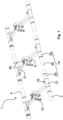
- FIG. 1 A fluid distribution arrangement 1 of a temperature control circuit is shown.
- the illustrated fluid distribution arrangement 1 is designed for controlling the temperature of an electrical device.
- the electrical device is not shown, but the electrical device is in particular a battery, expediently comprising several battery modules.
- the fluid distribution arrangement 1 has at least one supply line 2 and at least one return line 4 running substantially parallel to the supply line 2.
- the supply line 2 is fluidically connectable to a supply line
- the return line 4 is fluidically connectable to a return line.
- the supply line and the return line are fluidically connectable to the electrical device by means of the supply line 2 and the return line 4.
- a tempering fluid and/or a tempered fluid is passed from the supply line into the supply line 2, from the supply line 2 to the electrical device and from the electrical device via the return line 4 into the return line.
- the flow line 2 is connected by means of at least one supply line 6 to a connection connector 10 for fluidic connection to the electrical device.
- the return line 4 is connected by means of at least one discharge line 8 to a further connection connector 10 for fluidic connection to the electrical device.
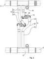
- This inventive embodiment enables the inventive arrangement that, as in the Fig. 1 and 2 shown, the flow line 2 and the return line 4 are arranged at a distance from one another such that the supply line 6 and the discharge line 8 and the respective connection connectors 10 are arranged between the flow line 2 and the return line 4.
- the electrical device designed as a battery with a plurality of battery modules has on each battery module a connection means for fluidic connection to the connection connector 10 of the supply line 6 and a connection means for fluidic connection to the connection connector 10 of the discharge line 8.
- FIG. 3 An advantageous embodiment of a distributor piece 12 is shown, which is arranged or formed on the supply line 2 and/or return line 4.
- the supply line 2 is fluidically connected to the supply line 6 and/or the return line 4 is fluidically connected to the discharge line 8.
- the supply line 2 and the return line 4 have a plurality of distributor pieces 12, in particular nine distributor pieces 12 each.
- the distributor pieces 12 are arranged at equal and/or different distances from one another and are fluidically connected by pipe elements 14 formed between the respective distributor pieces.
- the distributor piece 12 has a mounting device 16.
- the mounting device 16 By means of the mounting device 16, the distributor piece 12 can be mounted at a specific position.
- the mounting device 16 is expediently as shown in Fig. 4 shown, designed as a bore formed on a bearing bracket, so that the distributor piece 12 or the mounting device 16 can be screwed to a corresponding counterpart at a specific position.
- Fig. 1 to 3 it can be provided that more than one supply line 6 or discharge line 8 can be connected or is connected to the respective distributor piece 12.
- more than one supply line 6 or discharge line 8 can be connected or is connected to the respective distributor piece 12.
- the Fig. 1 to 3 In the illustrated versions of the distributor pieces 12, two supply lines 6 or two discharge lines 8 can be connected or are connected.
- Fig. 3 In the embodiment of the distributor piece 12 shown, this has at least one connecting element 18 for fluidic plug-in connection of the supply line 6 or the discharge line 8.
- the supply line 6 and the discharge line 8 are each shown in a state connected to the connecting elements.
- the connecting element(s) 18, as shown in Fig. 3 shown is/are designed as a plug-in mandrel(s).
- the supply line 6 or the discharge line 8 is expediently plugged onto the respective plug-in mandrel.
- the respective distributor piece 12 has a corresponding number of connecting elements, in particular as in Fig. 3 shown mandrels.
- a special embodiment of the fluid distribution arrangement 1 provides that the supply line 6 and/or the discharge line 8 advantageously have at least one corrugated pipe section 20 with a corrugated pipe jacket and at least two smooth pipe sections 22 with a smooth pipe jacket.
- This embodiment is particularly suitable in Fig. 2 shown. It can be expediently provided that the at least one corrugated pipe section 20 is formed between the smooth pipe sections 22.
- the flow line 2 and/or the return line 4 has at least one pipe element 14.
- a pipe element 14 is arranged between two distributor pieces 12 or with the respective distributor pieces 12, as in Fig. 1 shown, fluidically connected.
- the distributor pieces 12 to have a connection section 24, for example, a plug-on geometry or a plug-in geometry.
- Advantageous embodiments can consist in the respective pipeline elements 14 being connected to the connection section 24 in a force-fitting and/or material-fitting manner, in particular by laser welding or gluing.
- connection section 24 is designed as a plug-on geometry.
- the plug-on geometry can have a conical plug-in section 26, which widens conically in diameter into a Sealing section 28 merges, wherein a holding section 30, in particular with a radially outwardly projecting, expediently fully circumferential holding element 32, is advantageously arranged downstream of the sealing section 28.
- the holding element 32 can advantageously be designed as a circumferential holding tooth, as in Fig. 4 shown.
- a further advantageous variant can provide that a sealing groove 34 for receiving an annular seal is formed in the sealing section 28 or that an annular seal is received in the sealing groove 34.
- the flow line 2 and/or the return line 4, in particular their respective pipe elements 14, as shown by way of example in Fig. 1 shown, have at least one corrugated pipe section 36 with a corrugated pipe jacket and at least two smooth pipe sections 38 with a smooth pipe jacket.
- the distributor pieces 12 are designed as smooth pipe sections 38 and/or are arranged or designed in smooth pipe sections 38 of the respective supply line 2 or return line 4, in particular the respective pipe elements 14, and/or are fluidically connected to smooth pipe sections 38 of the respective supply line 2 or return line 4, in particular the respective pipe elements 14.
- the at least one corrugated pipe section 36 is formed between the smooth pipe sections 38.
- the connection connector 10 has a device connection 40 for connecting to a male or female plug connection of the electrical device and a line connection 42 for connecting to the supply line 6 or discharge line 8.
- the device connection 40 and the plug connection of the electrical device can expediently be configured to correspond to one another for a latching connection.
- the device connection 40 is as shown in Fig. 6 shown, designed as a male plug part, so that the male plug part of the device connection 40 can be inserted into a sleeve-like section of the plug connection.
- connection connector 10 is advantageously designed as an angled connector.
- the device connection 40 and the cable connection 42 are advantageously formed at an angle to one another. It has proven advantageous if this angle is 90°, in particular 100°, as shown by way of example in Fig. 6 shown, is.
- connection connector 10 is arranged in a locking manner in a connector receptacle 44 of a connector holder 46.
- a preferred embodiment of the connector holder 46 with a connection connector 10 arranged in its connector receptacle 44 is shown by way of example in Fig. 5 shown. According to the illustrated preferred embodiment of the connector holder 46, it has two connector receptacles 44. It can be expediently provided that a connection connector 10 of the supply lines 6 or a connection connector 10 of the discharge lines 8 is arranged in each of the two connector receptacles 44.
- the connector holder 46 is designed such that the connection connector 10 or the device connection 40 of the connection connector 10 is held axially to the plug connection, preferably such that the device connection 40 is held with the male plug part in the sleeve-like section of the plug connection.
- connection connector 10 of the supply line 6 and the connection connector 10 of the discharge line 8 are arranged jointly on the connector holder 46, each latching in a connector receptacle 44.
- this embodiment is shown in the Fig. 1 and 6 shown.
- the connector holder 46 has a mounting means 48 for fixing to a positioning device, in particular for fixing to the electrical device itself.
- the mounting means 48 can be designed as a through-opening through which a screw or a threaded bolt can be passed through and screwed to a corresponding threaded element, such as a nut or a threaded hole.
- the connector holder 46 has at least one C-shaped connector receptacle 44 with two radially elastic holding arms 50.
- the Fig. 5 The connector holder 46 shown has two C-shaped connector receptacles 44.
- the C-shaped connector receptacle 44 is designed such that, as in Fig. 5 shown, clampingly engages around a cylindrical bearing section 52 of the connection connector 10.
- The, in particular C-shaped, connector receptacle 44 and the connecting connector 10 are expediently designed to correspond to one another in such a way that the connecting connector 10 is blocked against displacement axially to a longitudinal axis X of the cylindrical bearing section 52 and is reversibly fixed in at least one installation position in a force-fitting manner against rotation about the longitudinal axis X of the cylindrical bearing section 52.
- the bearing section 52 of the connecting connector 10 is designed as a circumferential bearing groove, which, as in Fig. 6 shown, is formed by two groove walls 51 axially spaced from the longitudinal axis X.
- the groove walls 51 are expediently designed and arranged such that the radially elastic holding arms 50 of the connector receptacle 44 are positively blocked in the axial direction relative to the longitudinal axis X, so that the displacement of the connecting connector 10 axially relative to its longitudinal axis X is blocked in the bearing section 52.
- connection connector 10 in the bearing section 52 and the holding arms 50 of the connector receptacle 44 having locking means corresponding to one another such that the connection connector 10 can be fixed in the connector receptacle 44 in a force-fitting manner in at least two installation positions rotated relative to one another about the longitudinal axis X of the cylindrical bearing section 52.
- this variant can be provided by means of a toothed structure 54 on the holding arms 50.
- the locking means of the holding arms 50 are accordingly advantageously designed as a toothed structure 54 on the side of the holding arms 50 facing the bearing section 52.
- the locking means of the bearing section 52 are expediently designed, as shown, as at least four locking knobs 56 that are evenly distributed over the circumference of the bearing section 52 and project radially from the bearing section 52.
- a design can be expediently provided according to which at least two locking knobs 56 are always engaged with the toothed structure 54 such that the connection connector 10 is held in a force-fitting manner against rotation about the longitudinal axis X of the cylindrical bearing section 52.
- the toothed structure 54 and the locking knobs 56 are designed such that, when a certain torque is applied to the connecting connector 10 about the longitudinal axis X of the bearing section 52, the locking knobs 56 act on the toothed structure 56 in such a way that the radially elastic retaining arms 50 are widened and the locking knobs 56 are thereby lifted out of the toothed structure 54.
- this has the consequence that the force-locking securing is canceled and a rotation and repositioning of the connecting connector 10 relative to the connector holder 46 is possible.
- connection connectors 10 can no longer be rotated into different angular positions, but are held in the respective end position in the connector holders 46.
- the angular positions of the connection connectors 10 are thus after the insertion of the The connection connector 10 is positively inserted into the connector holder 46.
- connection connector 10 preferably has at least one retaining groove 60, preferably two axially extending retaining grooves 60, on its outer circumference, and the connector holder 46 has at least one retaining extension 62, preferably two retaining extensions 62, which are arranged and configured relative to one another such that the connection connector 10 is held in a single, defined position by the engagement of the retaining extensions 62 in the retaining grooves 60.
- At least one retaining extension 62 is arranged on an elastically deformable retaining arm 50, which is elastically movable radially and/or circumferentially relative to the connection connector 10, so that the connection connector 10 can initially be inserted into any angular position when inserted into the connector holder 46 and then positively engages in the defined end position by a circumferential rotation about its own axis.
- the holding extensions 62 slide into the holding grooves 60.
- at least one of the holding arms 50 is manually elastically deformable for releasing the connection connector 10 from the connector holder 46, so that the holding extensions 62 can be moved out of the holding grooves 10 and the connection connector 10 can be rotated out of the end position and removed from the connector holder 46.
- connection connector 10 according to the invention for a fluid distributor arrangement 1 according to one of the preceding embodiments has the features relating to the connection connector 10 of at least one of the aforementioned embodiments.
- a connector holder 46 according to the invention for a connection connector 10 of a fluid distribution arrangement 1 according to one of the preceding embodiments has the features relating to the connector holder 46 of at least one of the aforementioned embodiments.
- the invention is not limited to the illustrated and described embodiments, but also encompasses all equivalent embodiments within the meaning of the invention. It is expressly emphasized that the embodiments are not limited to all features in combination. Rather, each individual partial feature can have inventive significance in isolation from all other partial features. Furthermore, the invention is not yet limited to the combination of features defined in claim 1, 13, or 14, but can also be defined by any other combination of specific features of all the individual features disclosed as a whole. This means that, in principle, practically every individual feature of claim 1, 13, or 14 can be omitted or replaced by at least one individual feature disclosed elsewhere in the application.
Landscapes
- Engineering & Computer Science (AREA)
- General Engineering & Computer Science (AREA)
- Mechanical Engineering (AREA)
- Life Sciences & Earth Sciences (AREA)
- Sustainable Development (AREA)
- Sustainable Energy (AREA)
- Power Engineering (AREA)
- Transportation (AREA)
- Manufacturing & Machinery (AREA)
- Chemical & Material Sciences (AREA)
- Chemical Kinetics & Catalysis (AREA)
- Electrochemistry (AREA)
- General Chemical & Material Sciences (AREA)
- Quick-Acting Or Multi-Walled Pipe Joints (AREA)
Applications Claiming Priority (1)
| Application Number | Priority Date | Filing Date | Title |
|---|---|---|---|
| DE102023126089.8A DE102023126089A1 (de) | 2023-09-26 | 2023-09-26 | "Fluidverteileranordnung eines Temperierkreislaufes" |
Publications (2)
| Publication Number | Publication Date |
|---|---|
| EP4530120A2 true EP4530120A2 (fr) | 2025-04-02 |
| EP4530120A3 EP4530120A3 (fr) | 2025-05-07 |
Family
ID=92925867
Family Applications (1)
| Application Number | Title | Priority Date | Filing Date |
|---|---|---|---|
| EP24202892.6A Pending EP4530120A3 (fr) | 2023-09-26 | 2024-09-26 | Dispositif de distribution de fluide d'un circuit de thermorégulation |
Country Status (2)
| Country | Link |
|---|---|
| EP (1) | EP4530120A3 (fr) |
| DE (1) | DE102023126089A1 (fr) |
Families Citing this family (1)
| Publication number | Priority date | Publication date | Assignee | Title |
|---|---|---|---|---|
| DE102024130887A1 (de) * | 2024-10-23 | 2026-04-23 | Mahle International Gmbh | Temperiersystem |
Citations (2)
| Publication number | Priority date | Publication date | Assignee | Title |
|---|---|---|---|---|
| WO2013170927A1 (fr) | 2012-05-14 | 2013-11-21 | Voss Automotive Gmbh | Dispositif de distribution de fluide à raccorder à un système de thermorégulation d'un accumulateur d'énergie modulaire et accumulateur d'énergie équipé d'au moins un dispositif de distribution de fluide de ce type |
| EP3525280B1 (fr) | 2018-02-09 | 2021-04-07 | Voss Automotive GmbH | Module de distribution de fluide pour un système de mise en température modulaire et système de mise en température |
Family Cites Families (10)
| Publication number | Priority date | Publication date | Assignee | Title |
|---|---|---|---|---|
| GB714824A (en) * | 1952-04-04 | 1954-09-01 | Tudor Ab | Improvements in or relating to connecting and cooling arrangements in electric storage batteries |
| US4927103A (en) * | 1988-11-14 | 1990-05-22 | Nicholson Richard J | Method and apparatus for piping support |
| DE10141672C1 (de) * | 2001-08-25 | 2002-11-14 | Rasmussen Gmbh | Anordnung aus einem Halter und einem zylindrischen Bauteil |
| KR101367210B1 (ko) * | 2011-12-09 | 2014-02-27 | 대한칼소닉주식회사 | 배터리 셀의 방열유닛 |
| KR102044426B1 (ko) * | 2015-12-04 | 2019-11-13 | 주식회사 엘지화학 | 전지모듈들을 균일하게 냉각시킬 수 있는 간접 냉각 시스템 및 이를 포함하는 전지팩 |
| CN207938755U (zh) * | 2018-02-09 | 2018-10-02 | 比亚迪股份有限公司 | 液冷管路和电源装置 |
| DE102020101259B4 (de) * | 2020-01-21 | 2023-08-03 | Dr. Ing. H.C. F. Porsche Aktiengesellschaft | Batterie für ein Kraftfahrzeug, Verfahren zur Montage einer Batterie und Kraftfahrzeug |
| KR102867401B1 (ko) * | 2021-05-07 | 2025-09-30 | 주식회사 엘지에너지솔루션 | 전지팩 및 이를 포함하는 디바이스 |
| DE102021126429A1 (de) * | 2021-10-12 | 2023-04-13 | Witzenmann Gmbh | Verfahren zum fluidleitenden Verbinden von mittels eines Fluids temperierten Funktionsmodulen, entsprechend temperierte Funktionsmodule und zugehörige Verbindungsvorrichtung |
| DE102022114847A1 (de) * | 2022-06-13 | 2023-12-14 | Witzenmann Gmbh | Fluidverteilungssystem, Batteriemodulanordnung und Verfahren zum fluidleitenden Verbinden von Batteriemodulen in einer Batteriemodulanordnung |
-
2023
- 2023-09-26 DE DE102023126089.8A patent/DE102023126089A1/de active Pending
-
2024
- 2024-09-26 EP EP24202892.6A patent/EP4530120A3/fr active Pending
Patent Citations (2)
| Publication number | Priority date | Publication date | Assignee | Title |
|---|---|---|---|---|
| WO2013170927A1 (fr) | 2012-05-14 | 2013-11-21 | Voss Automotive Gmbh | Dispositif de distribution de fluide à raccorder à un système de thermorégulation d'un accumulateur d'énergie modulaire et accumulateur d'énergie équipé d'au moins un dispositif de distribution de fluide de ce type |
| EP3525280B1 (fr) | 2018-02-09 | 2021-04-07 | Voss Automotive GmbH | Module de distribution de fluide pour un système de mise en température modulaire et système de mise en température |
Also Published As
| Publication number | Publication date |
|---|---|
| DE102023126089A1 (de) | 2025-03-27 |
| EP4530120A3 (fr) | 2025-05-07 |
Similar Documents
| Publication | Publication Date | Title |
|---|---|---|
| EP2957809B1 (fr) | Élément d'accouplement destiné au raccord flexible de deux éléments destinés à la conduction de média | |
| EP2264848B1 (fr) | Dispositif de fixation de câble | |
| EP3292603B1 (fr) | Entrée de ligne/câble | |
| EP3292602B1 (fr) | Passage de câble/ligne | |
| WO2013030102A1 (fr) | Appareil de montage préalable de bague coupante pour raccords filetés pour tube | |
| EP3522301A1 (fr) | Dispositif de raccordement et agencement d'alimentation en énergie | |
| EP2019765A1 (fr) | Dispositif et procédé pour fixer un moteur d'essuie-glace sur une tringlerie d'essuie-glace | |
| EP4167351A1 (fr) | Procédé de raccordement fluidique de modules fonctionnels thermorégulés au moyen d'un fluide, modules fonctionnels thermorégulés correspondants et dispositif de raccordement associé | |
| WO2007025494A1 (fr) | Couplage hydraulique a connexion a baionnette et ressort a boudin destine a la securite antitorsion | |
| DE102023126089A1 (de) | "Fluidverteileranordnung eines Temperierkreislaufes" | |
| EP2456030B1 (fr) | Vissage de câble insérable sur un côté | |
| DE102015007630A1 (de) | Kabelsatzhalter für ein Kraftfahrzeug sowie Kraftfahrzeug mit Kabelsatzhalter | |
| EP1867024B1 (fr) | Dispositif de traversee de cable | |
| EP3715690A1 (fr) | Adaptateur pour raccords vissés de tuyaux flexibles | |
| DE202019104173U1 (de) | Vorrichtung zum Befestigen eines ersten Bauteils an einem zweiten Bauteil | |
| EP3085972A1 (fr) | Dispositif de fixation | |
| EP2568207B1 (fr) | Raccordement de tuyau | |
| DE102021207229A1 (de) | Verbindungsvorrichtung zum Verbinden eines ersten elektrischen Kontakts mit einem zweiten elektrischen Kontakt für einen Elektromotor und Elektromotor | |
| EP3659217B1 (fr) | Dispositif de contact | |
| EP4496135A1 (fr) | Connecteur à enveloppe mobile | |
| DE102014012335A1 (de) | Elektrisches Gerät | |
| EP3404777B1 (fr) | Raccordement d'appareil | |
| WO2005067100A1 (fr) | Dispositif de contact de masse dans le domaine automobile | |
| DE102022003974B4 (de) | Befestigungseinheit zur Befestigung einer Leitung an einem Fahrzeug | |
| EP0297218A2 (fr) | Raccord enfichable |
Legal Events
| Date | Code | Title | Description |
|---|---|---|---|
| PUAI | Public reference made under article 153(3) epc to a published international application that has entered the european phase |
Free format text: ORIGINAL CODE: 0009012 |
|
| STAA | Information on the status of an ep patent application or granted ep patent |
Free format text: STATUS: THE APPLICATION HAS BEEN PUBLISHED |
|
| AK | Designated contracting states |
Kind code of ref document: A2 Designated state(s): AL AT BE BG CH CY CZ DE DK EE ES FI FR GB GR HR HU IE IS IT LI LT LU LV MC ME MK MT NL NO PL PT RO RS SE SI SK SM TR |
|
| PUAL | Search report despatched |
Free format text: ORIGINAL CODE: 0009013 |
|
| AK | Designated contracting states |
Kind code of ref document: A3 Designated state(s): AL AT BE BG CH CY CZ DE DK EE ES FI FR GB GR HR HU IE IS IT LI LT LU LV MC ME MK MT NL NO PL PT RO RS SE SI SK SM TR |
|
| RIC1 | Information provided on ipc code assigned before grant |
Ipc: H01M 10/6568 20140101ALI20250401BHEP Ipc: H01M 10/6556 20140101ALI20250401BHEP Ipc: H01M 10/625 20140101ALI20250401BHEP Ipc: H01M 10/613 20140101ALI20250401BHEP Ipc: B60L 58/26 20190101ALI20250401BHEP Ipc: B60L 50/64 20190101AFI20250401BHEP |
|
| STAA | Information on the status of an ep patent application or granted ep patent |
Free format text: STATUS: REQUEST FOR EXAMINATION WAS MADE |
|
| 17P | Request for examination filed |
Effective date: 20250825 |