EP4530165A1 - Véhicule à chenilles suspendu dans une structure et électriquement relié à celle-ci - Google Patents
Véhicule à chenilles suspendu dans une structure et électriquement relié à celle-ci Download PDFInfo
- Publication number
- EP4530165A1 EP4530165A1 EP23200815.1A EP23200815A EP4530165A1 EP 4530165 A1 EP4530165 A1 EP 4530165A1 EP 23200815 A EP23200815 A EP 23200815A EP 4530165 A1 EP4530165 A1 EP 4530165A1
- Authority
- EP
- European Patent Office
- Prior art keywords
- vehicle
- suspension elements
- suspension
- drive unit
- circumferential
- Prior art date
- Legal status (The legal status is an assumption and is not a legal conclusion. Google has not performed a legal analysis and makes no representation as to the accuracy of the status listed.)
- Pending
Links
Images


Classifications
-
- B—PERFORMING OPERATIONS; TRANSPORTING
- B62—LAND VEHICLES FOR TRAVELLING OTHERWISE THAN ON RAILS
- B62D—MOTOR VEHICLES; TRAILERS
- B62D55/00—Endless track vehicles
- B62D55/06—Endless track vehicles with tracks without ground wheels
- B62D55/075—Tracked vehicles for ascending or descending stairs, steep slopes or vertical surfaces
-
- B—PERFORMING OPERATIONS; TRANSPORTING
- B62—LAND VEHICLES FOR TRAVELLING OTHERWISE THAN ON RAILS
- B62D—MOTOR VEHICLES; TRAILERS
- B62D55/00—Endless track vehicles
- B62D55/08—Endless track units; Parts thereof
- B62D55/18—Tracks
- B62D55/26—Ground engaging parts or elements
- B62D55/265—Ground engaging parts or elements having magnetic or pneumatic adhesion
Definitions
- the present invention relates to crawler type vehicles, especially ceiling vehicles, configured for traveling in a suspended manner, e.g., headlong at a ceiling structure. Further, the present invention refers to a method for suspending (especially hanging) and optionally also actively driving such a crawler type vehicle. In particular, the present invention refers to devices and methods according to features of the enclosed independent claims.
- the vehicle or transport medium should engage / interact in predefined manner with a predefined structure or underground, be it in an arrangement on the ground/floor (e.g. ground vehicles), be it a structure at a wall or at the ceiling (e.g. overhead cranes, wall crawling robots) e.g. in a storehouse or in machinery hall.
- ground/floor e.g. ground vehicles
- wall crawling robots e.g. in a storehouse or in machinery hall.
- the skilled person may differentiate between those vehicles which are provided for moving on the underground and those vehicles which are provided for moving along a ceiling structure, especially since the latter have to be suspended in secure manner also, in order to avoid going down. Therefore, there might be different approaches as to the kinematics ensuring interaction/engagement at the structure's interface.
- the object also includes providing for a suspension mechanism resp. suspension means allowing for securely suspending the (ceiling) vehicle on the ground or at a ceiling structure and establishing the electrical connection.
- the object may also include provision of an appropriate coupling mechanism for reliably coupling the vehicle with the structure.
- the object of the present invention may further include reliable hanging/suspending methods and optionally also actively driving methods for movably suspending such a vehicle on/at a structure, e.g., in suspended/hanging manner at a ceiling structure.
- the present invention solves the problems associated with the prior art by providing a device comprising the features of independent claim 1.
- Advantageous refinements and embodiments of the device are derived from dependent claims 2-14.
- the problem is solved by a method according to claim 15. If not explicitly excluded, the teachings of the subclaims can be combined arbitrarily with the teachings of the main claims and the subclaims.
- a crawler type vehicle for traveling in a suspended manner, especially headlong at a (ceiling) structure, wherein the vehicle exhibits:
- structure when it is referred to "structure” or “ceiling structure”, likewise, a structure which may also extend on the ground or along a wall or on an inclined plane (or the like) can be designated.
- the present invention can preferably be applied for ceiling vehicles being arranged at resp. traveling along a ceiling structure, and in addition, the present invention also allows for any motion along any structure with alternative orientation and/or arrangement.
- a “structure” or “ceiling structure” includes reference to any other “structure” exhibiting the features allowing for coupling with/to the inventive vehicle and de-/coupling kinematics.
- bus may denote any communication bus or a power supply bus, hence the term “pole/phase/line” to account for the poles of a DC power source, the phases of an AC power source, and the lines of a communication bus such as e.g., a I2C (TWI).
- I2C I2C
- the crawler type vehicle can exhibit at least one motor/actuator for actively driving the crawler type vehicle along the structure.
- the crawler type vehicle can follow an intended direction resp. an intended path of motion, especially in conjunction with appropriate sensor-actor-arrangements.
- the suspension arrangement is configured for active motion of the vehicle / the vehicles includes all embodiments wherein the vehicle/s can move on its/their own.
- actively moving designates a motion of the vehicle in relation to the structure actuated preferably by an electric motor of the vehicle connected to a drive unit such that the vehicle can move on its own inside the structure when the motor is activated.
- the choice of an appropriate motor can be carried out by the person skilled in the art in regard to existing motors and motor arrangements depending on the respective application / task / size of the respective crawler type vehicle.
- electrical contact designates a connection mechanism that enables the flow of electrical current between two or more conductive elements.
- the primary objective of an electrical contact is to establish a reliable and efficient means of transferring electrical signals or power.
- the electrical contacts must possess certain key properties, such as high electrical conductivity, mechanical robustness, corrosion resistance, and thermal stability.
- suitable materials for electrical contacts may include copper, copper alloys, or noble metals like gold, silver, or platinum, as well as various alloys and composite materials. It is imperative that the connection between the electrical contact and the pole/phase/line in the structure be established in a reversible manner, allowing for repeated engagement and disengagement without compromising its performance.
- reversible electrical contact mechanisms include sliding contacts, where two surfaces slide against each other to establish and break the connection, or roller contacts, where rotating elements facilitate electrical contact.
- a crawler type vehicle having first electrical contacts of the suspension elements configured for establishing an electrical connection with the structure, wherein the first electrical contacts exhibit a first slider for slidingly connecting to power rails of a corresponding pole/phase integrated in the structure and wherein the second electrical contacts exhibit a second slider for a slidable contact with conducting rails of the corresponding pole/phase, wherein each first slider is electrically connected to its corresponding second slider of the respective suspension element.
- the power rails can be integrated into the profiles of the structure, i.e., along the I-, L-, or T-profiles on one edge or side, preferably above the bearing surface of the profile.
- the vehicle comprises electronics connected to the internal bus for supplying the vehicle with power.
- These electronics can comprise but are not limited to communication modules for wireless or wired data exchange (vehicle-to-vehicle, vehicle-to-infrastructure, vehicle-to-mobile devices, etc.), a central control unit, sensors (proximity sensors, accelerometers, LiDAR, radar, etc.), a power management system (power converters (AC/DC, DC/DC), battery management, voltage regulators, ESD protection), motors, etc.
- the vehicle comprises an energy storage, such as a battery pack and/or super capacitors.
- the vehicle comprises connection means for connecting to equipment, wherein the equipment can be supplied with power via the connection means.
- connection means can be used to connect to a hoist, a robotic arm, studio equipment or any other kind of equipment. It is possible to combine the crawler type ceiling unit with a robotic arm.
- the robotic arm can e.g., be connected to the crawler type ceiling unit via coupling means of the type described in EP3705410A1 .
- the robotic arm can exhibit means for securely lifting objects.
- the robotic arm can e.g., be directly connected to a camera, lighting equipment, a welder or other tools.
- the second sliders are connected to the conducting rail such that the first slider has a defined potential before the first sliders are in proximity or connected to the power rail and when the suspension elements are decoupled from the structure, the first sliders are disconnected from the power rail before the second sliders are disconnected from the conducting rail.
- the first sliders are connected to the power rail before the second sliders are in proximity or connected to the conducting rail and when the suspension elements are decoupled from the structure, the second sliders are disconnected from the conducting rails before the first sliders are disconnected from the conducting rail.
- This configuration can be beneficial for low power applications and applications where the vehicle is particularly sensitive. It also reduces wear on the electric rails in the ceiling structure and shifts potential wear into the vehicle sliding contacts which are considered to be more simple to restore by maintenance actions.
- the vehicle exhibits
- circumferential track when it is referred to "circumferential track”, the disclosure also generally refers to closed loop guidings and lines and predefined contours along which the suspension elements are guided and/or driven.
- the disclosure when it is referred to "profiles” or “T-profiles”, the disclosure also generally refers to different kinds of profiles like e.g. I-profiles or L-profiles which may provide for advantageous/favorable arrangements in individual applications.
- the disclosure when it is referred to "(first) drive unit” or “drive unit of a first kind”, the disclosure especially refers to a unit accommodating kinematics allowing for traveling motion of the vehicle, i.e., comprising the suspension elements and means for guiding the suspension elements, especially circumferential tracks.
- a drive unit can e.g., comprise a housing with a first and second circumferential track engraved into the housing, wherein a chain comprising suspension elements is guided along the first and second circumferential track via pulleys.
- the suspension elements can, e.g., be coupled with the ceiling structure based on form fit (form closure, positive locking), especially exclusively form fit (no force-fit coupling).
- form fit can advantageously be provided by wheels or any other bearing points at a free end of the respective suspension element for being in contact with T-profiles or other kinds of profile rails of the ceiling structure (e.g., C-profiles or L-profiles or I-profiles).
- form fit provides for a preferred/superior manner of coupling in many circumstances, especially in comparison with magnet coupling or the like.
- the skilled person can decide which kind of profile (e.g., T-profile) is most appropriate.
- the drive unit's traveling motion (as to its spatial direction resp. locomotion) can be individual.
- the skilled person may implement the present invention for different kinds of spatial traveling motions, especially without any limitation, i.e., in 2D or even 3D degrees of freedom.
- each track exhibits at least three different guide/rail sections, namely: a first (linear) section in which each suspension element is engaged with the profile, wherein the suspension element performs a linear motion; and at least one second (curved) section in which each suspension element performs a decoupling motion (wherein each track may exhibit two second sections being arranged oppositely); and a third (linear) section in which the suspension elements are returned to couple again with the profile (for continuous, circumferential motion and engagement process).
- first and second tracks may define the trajectory of the respective free ends of the suspension elements (especially exhibiting at least one roller being attached to the respective suspension element) by any appropriate means (e.g. by a gliding/rolling contour, a chain drive, a timing belt, or any likewise mechanism or mechanical feature) which is configured for predefining a specific contour and for guiding the free ends resp. the rollers to follow that contour of the tracks.
- any appropriate means e.g. by a gliding/rolling contour, a chain drive, a timing belt, or any likewise mechanism or mechanical feature
- the vehicle is configured for moving along the ceiling structure in at least one spatial direction by decoupling a subset of the plurality of suspension elements from resp. coupling them into the structure, especially when said subset of suspension elements are guided along a curved section of the circumferential tracks.
- spatial direction designates a direction in space
- spatial direction may comprise a motion along a space axis in both directions along the space axis.
- in at least one spatial direction designates a one-dimensional motion (which is optionally bidirectional, i.e., back and forth) having one degree of freedom (especially linear motion).
- two-dimensional motion refers to a motion having two degrees of freedom (especially linear motion in a first spatial direction and in a second spatial direction, the second spatial direction e.g., being orthogonal to the first spatial direction, optionally also in bidirectional manner).
- the term "drive unit” especially may designate the whole assembly of drive components and kinematic components required for realizing the desired traveling motion. But the drive unit does not necessarily include any active motor or drive. Also, the drive unit may further comprise a case or chassis accommodating structural parts and elements for arrangement of any parts of the drive section. Further, the drive unit may also comprise structural parts or supports or beams for mounting and support of any hoist component or passenger/cargo transport components.
- the shape or dimension of the at least one drive unit can be defined individually according to specific applications.
- the cross-section geometry of the at least one drive unit is in the shape of a racecourse (parallel longitudinal sections and opposite semicircle sections).
- the cross-section geometry can also be circular or elliptical for example.
- the vehicle may (optionally) comprise different kinds of power units, drives, motors and actuators, not only for the drive units, but also for further functions as e.g., winch or hoist functions.
- the vehicle can be provided as a passive vehicle without any motor for driving the vehicle (then, the vehicle can be positioned e.g., via external forces which apply on a hoist mechanism or the like) or as an active vehicle exhibiting at least one motor interacting with the driving mechanism resp. with the suspension elements.
- the vehicle exhibits at least one power unit or motor for each resp. for the at least one drive unit, e.g., an electric motor which is coupled to an axis of rotation of a gear unit interacting with the respective circumferential track.
- the vehicle may optionally exhibit at least one motor interacting with a/the wheels of the suspension elements, in order to allow for motorized motion in a further spatial direction; thus, the wheels can be driven by any drive to actively drive along the profile rails.
- the vehicle may also exhibit at least one hoist (hoist unit) and a traction mechanism configured for lifting loads.
- the hoist unit can be fixed to and supported by the at least one drive unit.
- Each power unit, drive, motor and/or actuator of the vehicle can be coupled to a control unit of the vehicle.
- the control unit may control the type/kind of motion, and the control unit may also control e.g., a lifting action of a hoist unit e.g., in context with cargo tasks or logistic tasks in general.
- the vehicle may exhibit two or three drive units which can be arranged in predefined lateral distance to each other (e.g. defined/connected via cross-beams or the like), and in case the vehicle should be driven in active manner (which configuration is optional), each drive unit may exhibit at least one drive/motor for (actively) driving the suspension elements along the circumferential tracks, and these drives/motors can be controlled depending on each other, e.g. via the speed of rotation.
- a traveling direction can be controlled also, especially in combination with actively driven wheels of the suspension elements being driven along the profile rails of the ceiling structure (which active drive aspect is optional, too).
- the term “drive unit” especially refers to a unit accommodating kinematics allowing for traveling motion of the vehicle.
- the term “drive unit” not necessarily implies presence of active motors; rather, the traveling motion may also be induced by external forces; thus, the term “drive unit” not necessarily implies the unit to be driven in active manner.
- driving motion (which designates circumferential motion along the first and second circumferential tracks) is different from the term “traveling motion” which designates a motion of the vehicle itself.
- the kinematics according to the present invention allow for equipping the vehicle with at least one drive unit, i.e., there is no need of providing more than one drive unit; preferably, two or even three drive units (especially in view of improved form-fit) allow for even more reliable suspension.
- the vehicle exhibits:
- the at least one drive unit comprises an even number of suspension elements. This allows easy installation and synchronization between the structure and the vehicle due to periodicity because it ensures in a very easy and reliable manner that no polarity swaps can occur on the conducting rails due to a suspension element coupling into a profile with a power rail of opposite polarity. This also facilitates scalability of the structure.
- the at least one drive unit must comprise a number of suspension elements equal to an integer multiple of the number of poles/phases/lines of the electrical bus.
- the suspension elements configured for establishing an electrical connection with the structure are distributed along the at least one first drive unit such that when the vehicle is moving along the structure a suspension element for the electrical connection of a respective pole/phase/line is coupled into the structure before the otherwise last suspension element connected to the respective pole/phase/line is decoupled from the structure. This helps to ensure an uninterrupted connection with the respective pole/phase/line while moving the vehicle on the ceiling structure.
- the at least one drive unit of the vehicle is configured for enabling a closed loop trajectory of the suspension elements
- the first and second circumferential tracks are shaped in such a manner that the suspension elements are decoupled from/into the structure only when passing a curved section of the tracks
- the suspension elements are fixedly attached/coupled by means of a first pulley to/with the first circumferential track
- the suspension elements are guided within the second circumferential track by means of a second pulley respectively
- the first and second pulley preferably are arranged at a lever arm of the respective suspension element
- the respective suspension element preferably has an L-shape
- each suspension element exhibits a first pulley and a second pulley arranged in longitudinal distance with respect to the first pulley at a lever arm of the respective suspension element, wherein the suspension element is coupled to the first and second tracks via the first and second pulleys.
- each suspension element exhibits a lever arm accommodating/supporting a/the pulley guided by the second track, wherein the pulley is arranged at a free end of the lever arm, and wherein in a linear section of the track, the lever arm is pointing in the driving/traveling direction, at least roughly, wherein the suspension elements are connected to each other by means of longitudinal connecting elements, especially by longitudinal connecting elements being connected at the axis of a/the first pulley of the respective suspension element, thereby forming a closed loop of interrelated suspension elements distanced to each other in the predefined raster, the first circumferential track exhibits a chain or is provided/defined by a chain forming a closed loop of interrelated chain elements connecting the suspension elements, wherein the vehicle exhibits a plurality of counter wheels, especially configured and arranged for frontally interacting with the ceiling structure, wherein the plurality of counter wheels are preferably coupled to/with the first circumferential track, especially coupled to chain elements of the first circumferential track; wherein the vehicle
- the vehicle exhibits a further drive unit which exhibits the same configuration as a/the first drive unit but with mirror-inverted arrangement of the further suspension elements and further circumferential tracks, wherein the further suspension elements are guided/driven in a direction opposite to the guiding direction of the suspension elements of the first drive unit, especially such that both the respective suspension elements and further suspension elements are simultaneously de-/coupling to/from the structure, the at least one first drive unit is configured for lifting the respective suspension element out of the structure in an unloaded state, especially such that the at least one first drive unit provides for both decoupling kinematics for a subset of momentarily unloaded suspension elements and suspension of the vehicle by a subset of momentarily loaded suspension elements at the
- the at least one drive unit has a substantially plane configuration.
- the vehicle exhibits at least two drive units arranged in parallel to each other.
- the circumferential tracks are respectively guided/driven in a plane, extending in two-dimensional manner.
- the at least one first drive unit is coupled by means of at least three suspension elements.
- the respective suspension element has an L-shape which provides for two arms defining the relative arrangement of a/the wheel and first and second pulleys of the respective suspension element. This configuration is favourable in view of scaling, allows for providing, along a rectilinear section of the tracks, a section in which suspension of the vehicle can be secured by scalable number of suspension elements.
- this arrangement allows for high accuracy of the predefined path and amount of the predefined motion of a free end (or of a/the wheel) of the respective element.
- the lever arm pointing (roughly) in the driving/traveling direction (second spatial direction) allows for effecting a great effective length of the lever arm section between first and second pulley, thereby ensuring considerable pivot motions for de-/coupling kinematics.
- this configuration allows for adjusting the shape/contour of the track by means of a chain tensioning device or other kinds of deviating point/pulley.
- the first circumferential track can be defined by a chain connecting the suspension elements.
- the term "chain” may also refer to a belt or cable or any other circumferential driving element that allows to follow/constrain to the circumferential track(s).
- the skilled person may decide which configuration of the chain is most appropriate in/for an individual application.
- the plurality of counter wheels allows for securing the vehicle's position with respect to the further (second) spatial direction (normal force being exerted on the structure in case the vehicle is arranged in a headlong manner upside down or at an inclined plane).
- the plurality of counter wheels may/can provide for a counter force drive module (counter force unit) which allows/facilitates even more secure positioning and suspension of the vehicle, e.g., on an inclined plane or in an overhead arrangement (upside down).
- the free ends of the counter wheels can be configured in dependence on the type/shape of the (ceiling) structure, e.g., the free ends of the counter wheels exhibit at least one wheel or pulley.
- a further first drive unit accommodating further circumferential tracks configured for synchronous circumferential motion of further suspension elements facilitates scaling up and favors configurations for vehicles having high stability and security requirements. Further first drive units also provide for high security and even self-locking suspension.
- the closed loop of interrelated suspension elements distanced to each other in the predefined raster ensures accurate relative arrangement of the plurality of suspension elements with respect to each other.
- Each longitudinal connecting element preferably exhibits the shape of a rod or stick or small lever arm.
- the plurality of longitudinal connecting elements may provide for a closed loop of interrelated elements which form a kind of chain or the like which is guided/driven along the circumferential track(s).
- a further (first) drive unit with mirror-inverted arrangement advantageously fits with a ceiling structure being made of or being provided by T-profiles or T-shaped support elements (especially T-shaped ceiling beams).
- the provided kind of de-/coupling kinematics also provides for a quite energy-efficient and force-efficient manner of driving/traveling/advancing. Also, minimizing forces and momentum in context with the de-/coupling process also favors potentially very fast crawling motion(s) even in case the vehicle exhibits considerable weight or has to lift considerable loads.
- the parallel arrangement of multiple (first) drive units that have a substantially plane configuration in a lateral view (side-face) favors implementation of two or even three (first) drive units in a quite narrow/slim arrangement, respectively.
- the guiding/driving of circumferential tracks in a plane, extending in two-dimensional manner favors implementation of a linear traveling motion combined with a motion along the ceiling structure, orthogonal to the traveling motion of the circumferential tracks.
- the coupling of the vehicle by means of at least three suspension elements provides for distributing any forces and momentum via a plurality of suspension elements, thereby ensuring a good security and stability level.
- the L-shape of the configuration allows for a robust design; also, the suspension elements can easily be designed individually depending on specific applications and specific ceiling structures, by adapting the design of the lever arms.
- the vehicle comprises four first drive units, all of which are arranged in parallel, with two of the first drive units with mirror-inverted arrangement of the further suspension elements and further circumferential tracks, wherein the further suspension elements are guided/driven in a direction opposite to the guiding direction of the suspension elements of the first drive unit, especially such that both the respective suspension elements and further suspension elements are simultaneously de-/coupling to/from the structure, wherein the first drive units are arranged pairwise, wherein the pairs are horizontally spaced apart, wherein at least one first drive unit of each pair comprises suspension elements for establishing an electrical connection to the structure.
- the mirror-inverted pairwise arrangement reduces slip and ensures that the vehicle retains his orientation with respect to the structure.
- the space between the pairs of the first drive units can be dimensioned such that all potential additional components can be fit between the pairs. Because in both pairs there is at least one drive unit with suspension elements for establishing an electrical connection to the structure, electrical signals and power can be routed inside the vehicle particularly easily.
- every suspension element is configured for establishing an electrical connection with the structure. This can be beneficial for applications where a particularly high amount of power is to be transferred via the suspension elements because the current can be distributed over many suspension elements, reducing heat creation and wear of the components. Additionally, with this redundant configuration, a disconnection of single suspension elements would not result in an open loop of the electrical connection line.
- the vehicle exhibits:
- the motors receive power from an internal energy storage unit, such as a battery pack and/or a super capacitor.
- a super capacitor can be especially beneficial for vehicles with high accelerations and short acceleration and braking times.
- the vehicle exhibits two conducting rails, wherein the conducting rails are placed on opposite sides of one or more first drive units, wherein the second slider of one suspension element is placed on one side and the second slider of a second suspension element is placed on another side.
- the two conducting rails are placed on one (mutual) side of the at least one first drive unit vertically spaced apart, wherein the second slider of one suspension element is placed on one side at a corresponding first height and the second slider of a second suspension element is placed on the same side at a corresponding second height.
- the first variant has beneficial properties for ESD-protection because the first drive unit placed between the conducting rails prevents any material short-circuiting the two rails.
- a vehicle comprising two first drive units with two conducting rails on one side each can allow the vehicle to connect, e.g., to all phases of the (domestic) power grid, to a TWI and additionally to a DC or AC supply, or to more complex communication busses.
- the vehicle exhibits four conducting rails, wherein two conducting rails are each placed on opposite sides of one or more first drive units, wherein the second sliders of two suspension elements are placed on one side and the second sliders of two second suspension elements are placed on another side, and wherein the two conducting rails that are placed on one side of the at least one first drive unit are spaced vertically apart, wherein the second sliders of the suspension elements are placed on one side at a corresponding first height and the second sliders of the second suspension elements are placed on the same side at a corresponding height.
- the internal bus of the vehicle consists of four lines, wherein the four conducting rails preferably accompany linear sections of the first drive unit(s).
- a method of suspending a crawler type vehicle especially suspending a crawler type vehicle according to one of the described embodiments, at/from a structure for traveling in a suspended manner along the structure, especially headlong the structure, is provided.
- the vehicle is suspended by means of a plurality of suspension elements coupling the vehicle to the structure, wherein a circumferential guiding/driving motion is defined by first and second circumferential tracks having a different circumferential shape/contour, wherein the suspension elements are attached to the first circumferential track at predefined first longitudinal positions corresponding to a raster defined by the structure, wherein the vehicle is suspended such that it can move along the structure by decoupling a subset of the plurality of suspension elements from resp.
- the vehicle is electrically connected to a bus integrated into the structure, wherein it is preferably ensured that at least two suspension elements are connected to at least one respective pole/phase/line of the bus at all times, preferably to each pole/phase/line of the bus.
- the structure can exhibit designated areas with poles/phases/lines in which the vehicle can move to recharge or to communicate and receive updates. However, it is preferred that the whole structure exhibits poles/phases/lines of at least one bus.
- the vehicle and structure have to be coordinated such that there is always one suspension element of a corresponding pole/phase/line connecting to the bus in the structure by coupling the suspension element into the structure before the otherwise last suspension element that is currently connected to the same pole/phase/line in the structure gets disconnected from the bus from a decoupling process of the suspension element.
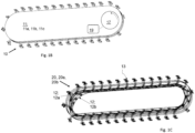
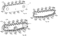
- the present invention provides for a vehicle 10, especially a ceiling vehicle 10, e.g., having a first drive unit 11 (crawler track-like), especially a first drive unit 11a and a further first drive unit 11b and optionally also a further first drive unit 11c.
- the vehicle 10 is configured for traveling along a (ceiling) structure 1 exhibiting a predefined raster 1a which is, e.g., defined by T-profiles resp. T-rails 1.1 or any such profile rails.
- the profiles 1.1 exhibit at least one wheel tread 1.2, and an electrical bus 1.3 providing for electric signals or energy is arranged at the profiles.
- the vehicle 10 is coupled to the structure 1 and suspended via a plurality of suspension elements 13 (e.g., each including at least one chain element), wherein at least a subset of the suspension elements 13c, 13d each exhibit two electrical contacts 13.4, 13.7 respectively, wherein a first electrical contact 13.4 is configured to connect to the electrical bus 1.3, and a second electrical contact 13.7 connected to the first electrical contact 13.4 is electrically connected to an internal bus of the vehicle 10.
- a crawler type vehicle arrangement 100 is composed of at least one (ceiling) vehicle 10 and at least one (ceiling) structure 1.
- the at least one drive unit 11 provides for a drive mechanism 11.1 with at least one motor 11.5 or actuator, which allows for circumferential motion of the suspension elements 13 along circumferential tracks 12, namely simultaneously along a first and a second circumferential track 12a, 12b, which tracks exhibit individual shapes/contours XZa, XZb.
- the tracks only extend two-dimensionally (2D), i.e., in a plane, and the shape is different at least in curved sections of the tracks.
- Each track 12a, 12b exhibits a parallel/linear section 12p (resp. two parallel sections) and a redirection/curved section 12r (resp. two curved sections).
- a lateral area resp. surface shell 11.2 of the at least one drive unit is preferably flat, plane, even, respectively on each lateral side. Such a configuration is also favorable in view of interconnection of several drive units.
- the vehicle 10 exhibits at least one further first drive unit 11b exhibiting first and second circumferential tracks 12a, 12b and accommodating a plurality of further suspension elements 13b which are arranged mirror-inverted, with respect to the suspension elements 13 of the first drive unit 11a.
- the drive units 11a, 11b provide for a traveling motion (e.g., by a synchronous guiding/driving motion of/to the suspension elements), and these drive units 11a, 11b can be interconnected, e.g., via cross-beams or the like.
- the first and second drive units 11a, 11b may provide for different driving motions, e.g., in order to force a nonlinear, but curved/curvilinear traveling motion.
- the desired/required traveling motion can be controlled via a control unit 30 coupled to at least one motor 11.5 or actuator.
- the vehicle 10 can be provided as a kind of passive vehicle which traveling motion is induced by external forces; in such a configuration, the inventive kinematics provide for hanging/suspending the vehicle, but not for actively driving the vehicle 10 for any traveling motion.
- the drive section may also comprise at least one gear unit 18 configured for interacting with the track(s) and an energy storage unit.
- a sensor arrangement 40 e.g., comprising position sensors and velocity sensors and/or weight sensors and/or gyroscopes, may provide sensor data to the control unit 30.
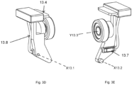
- Each suspension element 13 exhibits a first pulley 13.1 and a second pulley 13.2, and optionally, a wheel 13.3 is provided at the free end of the suspension element 13 (bearing point P13).
- the first and second pulleys are arranged on a lever arm 13.5 in distance from/to each other (y-offset, longitudinal extension y13 of lever arm); the bearing point P13 resp. the wheel 13.3 is arranged at a protruding section resp. suspension arm 13.6 (z-offset).
- a first electrical contact 13.4 conductive slider for energy transfer
- the first electrical contact 13.4 can e.g., also be provided via an L-shape extending above the wheel 13.3 or via counter wheels 16, i.e., rolling contact for connecting to a pole/phase/line of the electrical bus 1.3 on the bottom side of the profile units 1.1.
- the plurality of suspension elements 13 of a/the respective drive unit 11 can be interconnected via longitudinal connecting elements 15 which can ensure a closed loop 15a of interrelated suspension elements.
- the suspension elements 13 are coupled to the respective circumferential tracks.
- the suspension elements preferably exhibit a wheel 13.3 performing a rolling motion on the profile, allowing for motion which is orthogonal to the motion predefined and evoked by the tracks, wherein the wheel is positioned orthogonally with respect to the first and second pulleys.
- the wheel can be motorized by means of further actuators or motors.
- the first pulley 13.1 is engaged with the first or second circumferential track, thereby following that track; also, the second pulley 13.2 is engaged with the first or second circumferential track, thereby following that track (which is different from the track engaged by the first pulley, i.e., vice versa).
- the lever arm 13.5 is preferably L-shaped, especially provided as integral element in one piece (massive, solid).
- the structure 1 and its raster 1a is defined by profiles 1.1 being arranged in parallel and with similar distance (pitch) to adjacent profiles.
- Each profile is preferably configured to support geometries/surface(s) which are adequate for interaction with the wheel(s) of the suspension elements (e.g., T-profile, C-profile, L-profile, I-profile) and profiles at least in some areas of the structure exhibit poles/phases/lines of an/the electrical bus for interaction with the suspension elements, and a series of such profiles preferably provides for a planar surface at least in sections.
- the (respective) drive unit provides for de-/coupling kinematics 20 which ensure both vertical motion kinematics 20a and non-circular pivot motion kinematics 20b.
- de-/coupling of each suspension element 13 can be affected via circumferential motion along the tracks without the need of any axial telescopic motion within each suspension element.
- the suspension element 13 can be designed as a purely mechanic unit.
- the vehicle 10 may exhibit a hoist unit 50 providing for a traction mechanism 51 (especially with rope winch) and having at least one transmission means 53 (especially a rope).
- the hoist unit 50 can be powered via power rails and the suspension elements connected to the power rails.
- the first pulley 13.1 of each suspension element 13 rotates about a first pulley axis X13.1 and defines a first guiding point G13.1 (coupling the first track and the respective suspension element), and vice versa, the corresponding point of the corresponding circumferential track defines that first guiding point G13.1 for each suspension element.
- the second pulley 13.2 of each suspension element 13 rotates about a second pulley axis X13.2 (which is preferably aligned in parallel) and defines a second guiding point G13.2 (coupling the second track and the respective suspension element).
- an instantaneous center of rotation Cr of each suspension element is defined by the axis X13.1 of the first pulley 13.1 being coupled to the first track 12a, wherein coupling/attachment/fixation can be ensured e.g., at the axial section between a/the suspension arm 13.6 and the first pulley 13.1 (cf. Fig. 1G and 3B ).
- the two tracks 12a, 12b are arranged with respect to another in such a manner that the contacting/bearing point/area P13 of the respective suspension element 13 can be hooked or hitched on the ceiling structure.
- each suspension element 13 rotates about a wheel axis Y13.3 which is preferably aligned orthogonally to the first and second pulley axis X13.1, X13.2. Since each suspension element 13 is coupled to the tracks 12a, 12b in predefined positions, namely in a predefined first longitudinal position y12a via the first pulley 13.1 and in a predefined second longitudinal position y12b via the second pulley 13.2, when driving the tracks resp. when guiding the suspension elements along the tracks, the bearing point P13 at the free end of the suspension element 13 is guided according to the relative position/contour and distance of the tracks.
- (x) designates a/the first spatial direction (especially cross direction, especially direction of longitudinal extension of T-profiles), and (y) designates a/the second spatial direction (especially longitudinal direction or momentary driving direction of the drive units), and (z) designates a/the third spatial direction (especially vertical direction).
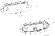
- Fig. 1A shows a (ceiling) vehicle 10 exhibiting a first drive unit 11 and suspension elements 13, wherein a subset of the suspension elements 13 is momentarily coupled to a/the ceiling structure 1, namely to T-profiles.
- the suspension elements 13 are guided and also actively driven along two circumferential tracks (not shown, cf. Fig. 1C ), and de-/coupling is carried out in curved sections of the tracks.
- the vehicle 10 shown in Fig. 1A is suspended/hanging at a ceiling structure. Nonetheless, the vehicle 10 may also be suspended in a similar structure being arranged on the ground or at the wall.
- the vehicle is not necessarily provided in the form of a ceiling vehicle; rather, Fig. 1A illustrated an application/use at a ceiling structure.
- Fig. 1B, 1C , 1D, 1E show separate components of the respective first drive unit 11, 11a, 11b, 11c.
- At least one drive 17 provides for circumferential motion of the tracks 12a, 12b, especially by means of at least one gear unit 18 engaging the tracks.
- the decoupling kinematics are provided within the curved sections 12r of the first and second circumferential tracks 12a, 12b.
- the suspension elements 13 remain in predefined relative positions at/with respect to the ceiling structure. In that section, the axis Y13.3 of the wheel 13.3 of the respective suspension element 13 is aligned parallel to the parallel section(s) 12p of the tracks.
- first drive units 11a, 11b some of these components may also be arranged in a mirror-inverted manner, especially the suspension elements (cf. Fig. 4A ).
- suspension elements cf. Fig. 4A .
- any detailed description of the figures relating to any separate/single component of the respective drive unit may also describe a similar configuration of any further drive units or any further redundant components.
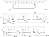
- Fig. 1F, 1G illustrate the curved sections 12r in more detail. It can be seen that both the radius of curvature and the distance of the tracks with respect to each other deviates/changes in value and direction, thereby effecting a pivot motion of the suspension arm 13.6 (protruding section) and the wheel 13.3 resp. bearing point P13 of the respective suspension element 13 (especially pivoting within the plane yz as shown in Fig. 1F and pivoting about an x-axis and around the instantaneous center of rotation Cr).
- both vertical motion kinematics 20a and non-circular pivot motion kinematics 20b can be provided by means of rigid/stiff components being guided/driven along two circumferential tracks with different shape/contour.
- Fig. 1H, 1J, 1K, 1L, 1M, 1N, 1O show some more details of the de-/coupling kinematics 20.
- the first track 12a has a curvature bent up (upwards), thereby effecting a slight lifting of the wheel 13.3 from the wheel tread 1.2, namely when the first pulley 13.1 is passing that section.
- the shape/contour XZb of the second circumferential track 12b runs (is arranged) within the shape/contour XZa of the first circumferential track 12a.
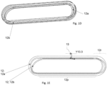
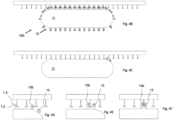
- Fig. 2A, 2B, 2C show a plurality of suspension elements 13 being interconnected via longitudinal connecting elements 15 which thereby ensure a closed loop 15a of interrelated suspension elements.
- the suspension elements 13 are coupled to the respective circumferential tracks 12a, 12b via the first and second pulleys 13.1, 13.2.
- the first and second pulleys 13.1, 13.2 are arranged on opposite lateral sides of the respective suspension element 13.
- the closed loop 15a of interrelated suspension elements is arranged between the first and second tracks 12a, 12b which extend on both lateral sides of the closed loop 15a.
- the tracks 12a, 12b can be made of any kind of rail guide system components, in particular including at least one chain, belt, cable or the like traction or transmission means.
- the tracks 12a, 12b may comprise different guide/rail sections coupled together, each exhibiting a different radius of curvature or being linear.
- the tracks 12a, 12b can be formed/made by one single continuous/coherent rail.
- Fig. 3A, 3B, 3C show some more details of the suspension elements 13 and the connecting elements 15.
- the connecting elements 15 are coupled to the lever arm 13.5 at the axis X13.1 if the first pulley 13.1, thereby facilitating pivot motion about that axis (resp. around the respective instantaneous center of rotation Cr).
- the suspension elements 13 exhibit a first electrical contact (slider) 13.4 that has a recess in its center to accommodate the wheel 13.3.
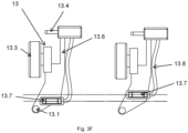
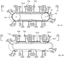
- Fig. 3D, 3E show details of alternative suspension elements 13c configured for establishing an electrical connection with the structure 1.
- the suspension elements 13c, 13d exhibit first sliders 13.4 and second sliders 13.7.
- the first slider 13.4 and second slider 13.7 are connected via a cable/wire 13.8.
- the first slider 13.4 extends in an L-shape above the wheel 13.3 and can engage with the pole/phase/line of an electrical bus 1.3 integrated into the structure 1.
- the second slider 13.7 is connected to a conducting rail 10.5 in the vehicle 10 when the vehicle is suspended via this suspension element 13c.
- Fig. 3F shows suspension elements 13c with second sliders 13.7 positioned at different heights but on one mutual side such that they can connect to different conducting rails 10.5 in the vehicle 10 which are placed on one (common) side of the first drive unit 11.
- Fig. 4A , 4B, 4C, 4D , 4E, 4F , 4G show an embodiment of a vehicle 10 exhibiting three first drive units 11a, 11b, 11c which can be interrelated/connected e.g., via cross-beams or the like.
- the suspension elements 13b of the further first drive unit 11b are arranged in mirror-inverted manner, but the suspension elements 13 of the further first drive unit 11c are arranged in the same manner as the suspension elements 13 of the first drive unit 11a.
- Fig. 4A , 4B, 4C, 4D , 4E, 4F , 4G show an embodiment of a vehicle 10 exhibiting three first drive units 11a, 11b, 11c which can be interrelated/connected e.g., via cross-beams or the like.
- the suspension elements 13b of the further first drive unit 11b are arranged in mirror-inverted manner, but the suspension elements 13 of the further first drive unit 11c are arranged in the same manner as the suspension elements 13 of the
- the vehicle 10 may only comprise two first drive units 11a, 11b. Some of the suspension elements 13 of the first drive units 11a, 11c are suspension elements 13c for establishing an electrical connection with the structure 1, and some of the suspension elements 13b of the further first drive unit arranged in mirror-inverted manner are also suspension elements 13d configured for establishing an electrical connection with the structure 1.
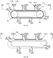
- Fig. 5A, 5B show a first drive unit 11 exhibiting only suspension elements 13c configured for establishing an electrical connection with the structure 1.
- the chain elements 15 and the gear unit 18 are blanked out.
- two poles/phases/lines of an electrical bus 1.3a are integrated into the structure 1.
- the first drive unit 11 depicted in Fig. 5A, 5B only connects to one pole/phase/line of the electrical bus 1.3a, while the other pole/phase/line of the electrical bus 1.3b can only be reached with a further first drive unit 11b arranged in a mirror-inverted manner, not shown here.
Landscapes
- Engineering & Computer Science (AREA)
- Chemical & Material Sciences (AREA)
- Combustion & Propulsion (AREA)
- Transportation (AREA)
- Mechanical Engineering (AREA)
- Carriers, Traveling Bodies, And Overhead Traveling Cranes (AREA)
- Electric Propulsion And Braking For Vehicles (AREA)
Priority Applications (2)
| Application Number | Priority Date | Filing Date | Title |
|---|---|---|---|
| EP23200815.1A EP4530165A1 (fr) | 2023-09-29 | 2023-09-29 | Véhicule à chenilles suspendu dans une structure et électriquement relié à celle-ci |
| PCT/EP2024/077250 WO2025068480A1 (fr) | 2023-09-29 | 2024-09-27 | Véhicule de type à chenilles suspendu et connecté électriquement à une structure |
Applications Claiming Priority (1)
| Application Number | Priority Date | Filing Date | Title |
|---|---|---|---|
| EP23200815.1A EP4530165A1 (fr) | 2023-09-29 | 2023-09-29 | Véhicule à chenilles suspendu dans une structure et électriquement relié à celle-ci |
Publications (1)
| Publication Number | Publication Date |
|---|---|
| EP4530165A1 true EP4530165A1 (fr) | 2025-04-02 |
Family
ID=88238044
Family Applications (1)
| Application Number | Title | Priority Date | Filing Date |
|---|---|---|---|
| EP23200815.1A Pending EP4530165A1 (fr) | 2023-09-29 | 2023-09-29 | Véhicule à chenilles suspendu dans une structure et électriquement relié à celle-ci |
Country Status (2)
| Country | Link |
|---|---|
| EP (1) | EP4530165A1 (fr) |
| WO (1) | WO2025068480A1 (fr) |
Citations (6)
| Publication number | Priority date | Publication date | Assignee | Title |
|---|---|---|---|---|
| JPS59227570A (ja) * | 1983-06-06 | 1984-12-20 | M T Hikawa:Kk | 吸盤付無限軌道帯 |
| US4641757A (en) | 1983-05-06 | 1987-02-10 | Robotic Systems, Inc. | Circulating latch transport mechanism for overhead cranes |
| US20180050747A1 (en) * | 2016-08-22 | 2018-02-22 | Eliot Kazakov | Multi-terrain wall climbing vehicle |
| DE202020100256U1 (de) * | 2020-01-17 | 2020-05-20 | MagneCat UG (haftungsbeschränkt) | Linearmotorisch angetriebenes Raupenfahrzeug |
| EP3705410A1 (fr) | 2019-03-08 | 2020-09-09 | Space Applications Services NV/SA | Dispositif et procédé de couplage androgyne ainsi qu'utilisation |
| CN110228541B (zh) * | 2019-05-08 | 2021-01-15 | 西安理工大学 | 一种爪刺对抓式履带爬壁机器人 |
-
2023
- 2023-09-29 EP EP23200815.1A patent/EP4530165A1/fr active Pending
-
2024
- 2024-09-27 WO PCT/EP2024/077250 patent/WO2025068480A1/fr active Pending
Patent Citations (6)
| Publication number | Priority date | Publication date | Assignee | Title |
|---|---|---|---|---|
| US4641757A (en) | 1983-05-06 | 1987-02-10 | Robotic Systems, Inc. | Circulating latch transport mechanism for overhead cranes |
| JPS59227570A (ja) * | 1983-06-06 | 1984-12-20 | M T Hikawa:Kk | 吸盤付無限軌道帯 |
| US20180050747A1 (en) * | 2016-08-22 | 2018-02-22 | Eliot Kazakov | Multi-terrain wall climbing vehicle |
| EP3705410A1 (fr) | 2019-03-08 | 2020-09-09 | Space Applications Services NV/SA | Dispositif et procédé de couplage androgyne ainsi qu'utilisation |
| CN110228541B (zh) * | 2019-05-08 | 2021-01-15 | 西安理工大学 | 一种爪刺对抓式履带爬壁机器人 |
| DE202020100256U1 (de) * | 2020-01-17 | 2020-05-20 | MagneCat UG (haftungsbeschränkt) | Linearmotorisch angetriebenes Raupenfahrzeug |
Also Published As
| Publication number | Publication date |
|---|---|
| WO2025068480A1 (fr) | 2025-04-03 |
Similar Documents
| Publication | Publication Date | Title |
|---|---|---|
| US20200269712A1 (en) | Wireless battery charging system for automatic guided vehicles | |
| EP4530165A1 (fr) | Véhicule à chenilles suspendu dans une structure et électriquement relié à celle-ci | |
| US20250222995A1 (en) | Crawler type ceiling vehicle configured for traveling along a structure, method of providing a crawler-like traveling motion along the structure, and use of at least one crawler type drive unit for providing de-/coupling kinematics for the traveling motion | |
| EP4530242A1 (fr) | Système d'ascenseur pour déplacer des personnes entre des étages, procédé d'utilisation d'un système d'ascenseur et procédé mis en uvre par ordinateur pour le planning d'itinéraire pour un système d'ascenseur | |
| EP4530164A1 (fr) | Agencement de suspension avec véhicules à déplacement omnidirectionnel et procédé utilisant des véhicules à déplacement omnidirectionnel | |
| CN121986048A (en) | Crawler-type carrier suspended in and electrically connected to structure | |
| EP4253204B1 (fr) | Véhicule plafonnier de type chenille conçu pour se déplacer le long d'une structure; procédé permettant de fournir un mouvement de déplacement de type chenille le long de la structure; et utilisation d'au moins une unité d'entrainement de type chenille pour fournir une cinématique de déplacement/accouplement pour le mouvement de déplacement | |
| EP4253203B1 (fr) | Véhicule de type de chenilles concu pour se déplacer le long d'une structure; procédé de suspension du véhicule permettant de mettre en oéuvre un mouvement de déplacement de véhicule de type é chenilles le long de la structure et utilisation d'au moins une unité d'entrainement de type de chenilles pour mouvement de déplacement actif | |
| EP4253202B1 (fr) | Véhicule de type chenille configuré pour se déplacer le long d'une structure, procédé d'accrochage/suspension du véhicule pour effectuer un mouvement de déplacement de type chenille le long de la structure, et utilisation d'au moins une unité d'entraînement de type chenille pour un mouvement de déplacement actif | |
| EP4530166A1 (fr) | Agencement de suspension de plafond avec véhicules à chenilles et structure modulaire et procédé de construction de la structure | |
| EP4273030B1 (fr) | Agencement de suspension de plafond présentant au moins une unité de plafond de type chenille ainsi que procédé de suspension de l'unité de plafond à une structure de plafond | |
| CN118973898A (zh) | 构造成沿结构行进的履带式车辆,用于沿结构进行履带式行进运动的挂接/悬挂车辆的方法,以及用于主动行进运动的至少一个履带式驱动单元的用途 |
Legal Events
| Date | Code | Title | Description |
|---|---|---|---|
| PUAI | Public reference made under article 153(3) epc to a published international application that has entered the european phase |
Free format text: ORIGINAL CODE: 0009012 |
|
| STAA | Information on the status of an ep patent application or granted ep patent |
Free format text: STATUS: THE APPLICATION HAS BEEN PUBLISHED |
|
| AK | Designated contracting states |
Kind code of ref document: A1 Designated state(s): AL AT BE BG CH CY CZ DE DK EE ES FI FR GB GR HR HU IE IS IT LI LT LU LV MC ME MK MT NL NO PL PT RO RS SE SI SK SM TR |
|
| TPAC | Observations filed by third parties |
Free format text: ORIGINAL CODE: EPIDOSNTIPA |
|
| STAA | Information on the status of an ep patent application or granted ep patent |
Free format text: STATUS: REQUEST FOR EXAMINATION WAS MADE |
|
| 17P | Request for examination filed |
Effective date: 20251001 |
|
| REG | Reference to a national code |
Ref country code: DE Ref legal event code: R079 Free format text: PREVIOUS MAIN CLASS: B62D0055075000 Ipc: B66C0009000000 |
|
| GRAP | Despatch of communication of intention to grant a patent |
Free format text: ORIGINAL CODE: EPIDOSNIGR1 |
|
| STAA | Information on the status of an ep patent application or granted ep patent |
Free format text: STATUS: GRANT OF PATENT IS INTENDED |
|
| RIC1 | Information provided on ipc code assigned before grant |
Ipc: B66C 9/00 20060101AFI20260109BHEP Ipc: B66C 17/00 20060101ALI20260109BHEP Ipc: B62D 55/075 20060101ALI20260109BHEP Ipc: B62D 55/265 20060101ALI20260109BHEP |
|
| INTG | Intention to grant announced |
Effective date: 20260129 |