EP4530233A1 - Station de chargement et/ou de déchargement robotisée pour un trieur de sacs - Google Patents
Station de chargement et/ou de déchargement robotisée pour un trieur de sacs Download PDFInfo
- Publication number
- EP4530233A1 EP4530233A1 EP23200165.1A EP23200165A EP4530233A1 EP 4530233 A1 EP4530233 A1 EP 4530233A1 EP 23200165 A EP23200165 A EP 23200165A EP 4530233 A1 EP4530233 A1 EP 4530233A1
- Authority
- EP
- European Patent Office
- Prior art keywords
- robot
- transfer point
- loading
- unloading station
- Prior art date
- Legal status (The legal status is an assumption and is not a legal conclusion. Google has not performed a legal analysis and makes no representation as to the accuracy of the status listed.)
- Pending
Links
Images




Classifications
-
- B—PERFORMING OPERATIONS; TRANSPORTING
- B65—CONVEYING; PACKING; STORING; HANDLING THIN OR FILAMENTARY MATERIAL
- B65G—TRANSPORT OR STORAGE DEVICES, e.g. CONVEYORS FOR LOADING OR TIPPING, SHOP CONVEYOR SYSTEMS OR PNEUMATIC TUBE CONVEYORS
- B65G47/00—Article or material-handling devices associated with conveyors; Methods employing such devices
- B65G47/52—Devices for transferring articles or materials between conveyors i.e. discharging or feeding devices
- B65G47/60—Devices for transferring articles or materials between conveyors i.e. discharging or feeding devices to or from conveyors of the suspended, e.g. trolley, type
- B65G47/61—Devices for transferring articles or materials between conveyors i.e. discharging or feeding devices to or from conveyors of the suspended, e.g. trolley, type for articles
-
- B—PERFORMING OPERATIONS; TRANSPORTING
- B07—SEPARATING SOLIDS FROM SOLIDS; SORTING
- B07C—POSTAL SORTING; SORTING INDIVIDUAL ARTICLES, OR BULK MATERIAL FIT TO BE SORTED PIECE-MEAL, e.g. BY PICKING
- B07C3/00—Sorting according to destination
- B07C3/02—Apparatus characterised by the means used for distribution
- B07C3/08—Apparatus characterised by the means used for distribution using arrangements of conveyors
-
- B—PERFORMING OPERATIONS; TRANSPORTING
- B65—CONVEYING; PACKING; STORING; HANDLING THIN OR FILAMENTARY MATERIAL
- B65G—TRANSPORT OR STORAGE DEVICES, e.g. CONVEYORS FOR LOADING OR TIPPING, SHOP CONVEYOR SYSTEMS OR PNEUMATIC TUBE CONVEYORS
- B65G2201/00—Indexing codes relating to handling devices, e.g. conveyors, characterised by the type of product or load being conveyed or handled
- B65G2201/02—Articles
- B65G2201/0235—Containers
- B65G2201/0238—Bags
Definitions
- the invention relates to a loading and/or unloading station for a pocket sorter.
- a loading and/or unloading station is known from EP 3 575 246 A1
- a similar device is also described by US 10296870 B1
- a conventional loading and/or unloading station and a pocket sorter are included in the DE 10 2019 205 980 A1 described.
- the devices known from the prior art have the disadvantage that the pocket must be pivoted out of the vertical alignment of a conveyor rail for loading and/or unloading in order to expose an upper opening of the pocket. Pivoting the pocket by, for example, 90°, is associated with correspondingly high forces acting on the pocket, especially at high conveyor speeds or cycle rates, which has a detrimental effect on the reliable operation of the pocket sorter.
- the loading and/or unloading station for a pocket sorter has a pocket feeder and a robot which is configured to load objects into or unload objects from a pocket provided by the pocket feeder at at least one transfer point of the loading and/or unloading station.
- the pocket guide can be designed to feed the pocket to the transfer point for loading and/or unloading while maintaining its orientation and to remove it from the transfer point while maintaining its orientation.
- the pocket is conveyed along a conveyor line of the pocket feed in a continuous or synchronized movement, preferably in a uniform synchronized movement.
- no external forces should act on the pocket except in the conveying direction. the pocket, especially no torques around the vertical axis of the pocket. Pocket rotation is not required.
- the pocket feeder can accordingly be a conveyor rail, for example a straight conveyor rail, which is guided essentially horizontally. It can be provided that the pockets of the pocket sorter are guided past the robot at a distance from the robot using the pocket feeder. The pockets can, for example, be guided past the robot tangentially to a movement circle of the robot. At the transfer point, the pocket feeder, in particular a conveyor rail of a pocket sorter, can be brought as close as possible to the robot, but at least to the extent that the at least one pocket to be loaded or unloaded is arranged within the access area of the robot.
- the pocket feeder can have a pocket opening at the transfer point, for example a guide rail that engages a support frame of the pocket and is designed to press the support frame into a horizontal orientation, thus pivoting the suspension point of the support frame on the carrier of the pocket, which is conveyed along the pocket feeder.
- a pocket opening at the transfer point for example a guide rail that engages a support frame of the pocket and is designed to press the support frame into a horizontal orientation, thus pivoting the suspension point of the support frame on the carrier of the pocket, which is conveyed along the pocket feeder.
- This can result in an upper opening of the pocket and/or a partially or completely open side wall being opened or at least enlarged, thus making it easier for the robot to access the interior of the pocket. Opening the pocket can also serve to sensorily detect the contents of the pocket, for example with regard to a geometric, physical or other property, or to read an identification of an object, for example a barcode, QR code or the like.
- the opening of the pocket at the transfer point can also be achieved by raising the pocket at the transfer point.
- the base of the pocket can be raised at the transfer point, for example. This can be achieved by the pocket resting on a base when it is arranged at the transfer point.
- the pocket can run onto a ramp when approaching the transfer point in the conveying direction of the pocket.
- a lifting table can be arranged at the transfer point, which raises the base of the pocket and is adjustable in the vertical direction.
- the pouch When the present application describes that the pouch is transported while maintaining its orientation, this means in particular that the pouch does not need to rotate about its vertical axis.
- the pouch it is not necessary for the pouch to be pivoted out of the vertical alignment of the pouch feed or a conveyor rail of the pouch feed for loading and/or unloading with its upper opening.
- the pouch can therefore, for example, remain aligned perpendicular to the conveying direction along the pouch feed or the conveyor rail for loading and unloading with its front and rear walls, which are wider than the side walls.
- at least the pouch is unloaded by accessing the pouch contents through one of the open side walls of the pouch, which are narrower than the front and rear walls.
- the pouch can also be loaded via the narrow side wall.
- loading can take place via the upper opening of the pouch.
- the pouch it is expedient for the pouch to be opened at the transfer point or immediately before it in the feed direction of the pouch along the pouch feed.
- the support frame at the upper opening in particular a support frame that limits the upper opening, can be pivoted into the horizontal position, for example with the aid of a guide rail, as is the case in the EP 2 418 160 B1 Deviating from the doctrine of EP 2 418 160 B1
- the pocket does not have to be rotated 90° out of the vertical alignment of the rail for loading and unloading.
- a transfer point is formed on each opposite side of the robot.
- the transfer points can each have a pocket feeder, in particular a conveyor rail that is at least partially horizontal, arranged at a distance from one another and preferably at the same height.
- the robot is arranged horizontally between the transfer points and can thus access the two transfer points on its two opposite sides.
- the objects to be loaded into the pockets or unloaded from the pockets can be supplied to or removed from the robot in various ways. In one embodiment, they are provided or removed by a person at a transfer station. removed. In another embodiment, the provision is carried out with the aid of a sorter, for example a horizontal sorter, preferably a cross-belt sorter or a tilt-tray sorter.
- a sorter for example a horizontal sorter, preferably a cross-belt sorter or a tilt-tray sorter.
- the horizontal sorter can have an end point from which the robot removes the object to be loaded into the pockets.
- the horizontal sorter can have an infeed, with which the objects unloaded from the pocket by the robot and placed on the infeed are inducted onto the horizontal sorter.
- the transfer station may have an object recognition system, in particular a camera-based object recognition system, which is configured to determine a relative orientation of an object held in the pocket and to be removed by the robot and to track a gripping movement of the robot.
- an object recognition system in particular a camera-based object recognition system, which is configured to determine a relative orientation of an object held in the pocket and to be removed by the robot and to track a gripping movement of the robot.
- the robot can, for example, be a multi-axis robot, preferably an articulated-arm robot, and/or have an end effector with a gripper.
- the gripper can be a pincer gripper or a vacuum gripper.
- the robot can be configured to reach into the pocket via the open side wall.
- the open side wall can be aligned parallel to the conveying direction of the pocket feeder or a conveyor rail of the pocket feeder.
- the pocket can have an identical open side wall on opposite sides.
- the pocket can also have closed front and rear walls. The closed front and rear walls can be wider than the side walls. Because the pocket has narrow side walls in the conveying direction and comparatively wider front and rear walls perpendicular to this, the pocket has a comparatively small thickness with a high capacity even when loaded in the conveying direction, which increases the loading capacity of the pocket sorter.
- the robot is thus configured to engage the pocket at the transfer point transversely, preferably perpendicularly, to the conveying direction of the pocket feed.
- the transfer point can have a pocket opening, which preferably has at least one pressure rail or is designed as such and which is designed to open an opening of a support frame of the pocket, via which the pocket is suspended in a carrier of the pocket sorter, from a position which is horizontal swiveled orientation to the horizontal or at least further towards the horizontal.
- Opening the bag can be used to expand the open side panel, thus increasing the lateral opening cross-section of the bag.
- pivoting the support frame can be used to open or further open the support frame itself and thus the top opening of the bag.
- the robot can therefore be configured to drop an object into the bag from above an opening of a support frame of a bag to be loaded that is open at the transfer point, or to insert it into the bag through the opening.
- the pocket feeder can be a conveyor rail of a pocket sorter, along which the pockets are conveyed with their wide front and back sides transverse to the conveying direction and while maintaining their alignment past the transfer point.
- a pocket feeder with a transfer point is arranged on opposite sides of the robot.
- the robot can be configured to remove an object that is provided in a pocket at a first of the two opposite transfer points from the pocket and load it into another pocket that is provided at the second of the two opposite transfer points.
- the robot can be configured to remove objects from another conveyor, for example a conveyor belt or a horizontal sorter, and load them into the pockets at the opposite transfer points or to unload them from the pockets and place them on the conveyor belt or horizontal sorter.
- the loading and/or unloading station can thus form an interface between a pocket sorter and a horizontal conveyor.
- Further embodiments of the invention therefore comprise an arrangement comprising a loading and/or unloading station of the type described above, a pocket sorter and a horizontal conveyor, preferably a horizontal sorter, for example a cross-belt sorter or a tilt-tray sorter.
- the horizontal conveyor can have a conveyor section that extends through an access area of the robot.
- the robot can be configured to remove objects from the horizontal conveyor and load them into a pocket at the transfer point.
- the horizontal conveyor transfers, for example, drops, the objects to be picked up by the robot at an end point, from which the robot removes the object.
- the robot can be configured to remove objects from a pocket at the transfer point and place them on the horizontal conveyor or an infeed of the horizontal conveyor.
- the horizontal conveyor can be configured to transport shipping containers, such as cartons, along the conveyor line.
- the robot can be configured to remove the objects from a pocket at the transfer point and place them in a shipping container located in the access area. This design eliminates the need for a reloading process, as the robot can load directly into a shipping container, thus eliminating the need to reload the objects from the horizontal conveyor into a shipping container.
- the transfer point and/or the end effector of the robot can have object recognition, for example, an optical camera system with image processing, an RFID scanner, a barcode scanner, and/or a QR code scanner.
- the object recognition can be configured to determine at least one object property of an object located in a pocket arranged at the transfer point.
- the object property can include an object size, an object orientation, an object geometry, an object volume, an object edge length, product data of the object, or a packaging type of the object.
- the robot preferably has a tracking system that can be configured to track a gripping movement of the robot for removing an object from the pocket at the transfer point, depending on the at least one object property. This can accommodate the fact that the objects can differ from one another in terms of their geometry and physical properties and can also be essentially randomly aligned in the pocket. The latter is particularly due to the fact that the objects are usually inserted into the pocket in an undefined manner during pocket loading.
- the transfer point can have a ramp rising upstream of the transfer point in the conveying direction of the pocket feed, which ramp is designed to support and preferably lift a bottom of a pocket arranged at the transfer point.
- the The robot can assist in grasping the object.
- the bag or its contents can be weighed.
- the loading and/or unloading station can have a weighing device at the transfer point, which is configured to determine the weight of an object lying in a pocket at the transfer point.
- the weighing device can preferably have a ramp that rises upstream of the transfer point in the conveying direction of the pocket feed.
- the robot can be configured to remove an object from a bag at the transfer point and place it at a packing station within the robot's access area for packing the object.
- the robot can also be configured to place at least one object into a shipping container provided at the transfer point.
- the shipping container can be a carton, a polybag, or product packaging for the at least one object.
- the robot can also be configured to select a suitable shipping container based on object data relating to the at least one object. The selection can be made based on master data of the object, such as physical properties of the object.
- the robot can also be configured to print a shipping label on the selected shipping container. Printing can therefore be limited to sticking a label on the shipping container, such as a carton.
- the robot can preferably also be configured to place the shipping container with the at least one object placed therein on a conveyor belt of a sorting device within the robot's reach, or to transfer it to an automated guided vehicle system, or to transfer it to a shipping container, preferably a roll container.
- the robot can be configured to remove an object from a bag at the transfer point and place it on a conveyor belt within the robot's reach.
- the conveyor belt can be configured to transport the object to a packing station for packaging.
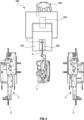
- FIGS. 1 and 2 describe an advantageous embodiment of a loading and/or unloading station 1 according to the invention for a pocket sorter 100.
- the pocket sorter 100 is not shown in detail, but can be designed, for example, according to the teaching of WO 2020/128941 A1 Further details of such a pocket sorter are also described in EP 4 074 628 A1 .
- the pouch sorter 100 can accordingly have a rail system 102, which, for example, connects the loading and unloading station 1 shown with a pouch buffer (not shown).
- a rail system 102 which, for example, connects the loading and unloading station 1 shown with a pouch buffer (not shown).
- individual pouches or groups of pouches 5 can be discharged from the pouch buffer and fed via the rail system 102 into the pouch feeders 2 on opposite sides of a multi-axis robot 3, each of which leads to a transfer point 4.
- the pouches 5 can be discharged into the pouch feeders 2 via switches 101 of the rail system 102.
- the pouch feeders 2 can consist of identical conveyor rails as the rest of the rail system 102. No special measures are required. In particular, it is not necessary for the pouch to be rotated by the pouch feeder 2 or the transfer point 4.
- the pocket can maintain its orientation throughout the entire process, from the discharge from the rail system 102, via the switch 101, and throughout the pocket feed 2, with its wide front and rear walls 10 perpendicular to the conveying direction along the respective rails 102.
- the pocket 5 remains aligned with its narrow side walls 8 parallel to the conveying direction throughout the entire process.
- the pocket 5 Upon reaching the transfer point 4, the pocket 5 runs onto a pocket opening 9. This opens the pocket.
- the pocket is opened in such a way that a support frame 14, which surrounds the upper opening 10 of the pocket, is horizontally is pivoted. In doing so, not only the opening 10 of the pocket 5 opens, but also its open side walls 8 are clamped open. This allows the multi-axis robot 3 easy access to an object 200 held in the pocket 5.
- the transfer point 4 also has an object recognition 15.
- the object recognition 15 can be configured to determine an object property of the object 200 held in the pocket 5.
- the object property can be, for example, an object size, an object orientation, an object geometry, an object volume, an object edge length, product data of the object, or a packaging type of the object.
- the information obtained in this way can be used in various ways.
- additional or alternative tracking of the robot 3 can be provided, which accesses the object data.
- a gripping movement of the gripper 7 on the end effector 6 of the robot 3 can be tracked according to an orientation of the object 200 in the pocket 5 in order to enable the reliable gripping of the object 200.
- the horizontal conveyor can, for example, be a conveyor belt.
- the horizontal conveyor can also be a cross-belt sorter or a tilt-tray sorter, which unloads objects to be loaded into a pocket 5 by the robot 3 into a terminal.
- the terminal can have object detection to enable the process-reliable gripping of the object dropped into the terminal by the gripper 7 of the robot 3.
- the conveyor belt can be the conveyor belt of an infeed into a horizontal sorter.
- FIG. 3 to 6 show further exemplary embodiments of a loading and/or unloading station 1 according to the invention in plan view.
- a transfer point 4 is arranged on opposite sides of the robot 3.
- the robot 3 is designed as an articulated arm robot, but can also be another multi-axis robot, a gantry robot, or another robot.
- the robot has a rod-shaped end effector 6 with a distal suction gripper 7.
- Via the pocket feeders 2, for example, pockets discharged from the revolving rail system of the pocket sorter via switches can be Transfer points 4.
- the transfer points 4 can, for example, be arranged in the manner Figures 1 and 2 be designed in the manner described.
- the robot 3 is designed to remove objects 200, which are provided in a respective pocket at one of the two transfer points 4, from the pocket and, in the embodiment according to Figure 3 to be placed on a conveyor belt 400, with which the object 200 is fed to a person 300 for further processing.
- an object 200 can be fed to the robot by the person 300 with the aid of the conveyor belt 400, wherein the robot 3 is configured to remove the object 200 from the conveyor belt 400 and place it in a pocket provided at one of the two transfer points 4.
- the conveyor belt 400 can, for example, be part of a packing station 500.
- the robot 3 can be configured to supply the person 300 with objects 200 intended for shipping.
- the person 300 can, for example, place the objects in a shipping container and prepare them for shipping, for example by placing them on a horizontal conveyor.
- the packing station 500 can, at least in one embodiment, be configured for the fully shipping-ready packaging of the objects 200, so that the objects leave the packing station 500 ready for shipping, in particular packaged in a shipping container, including address labeling.
- the packing station 500 has, in a modification of the embodiment according to Figure 3 Instead of the conveyor belt 400 for feeding the objects 200 to the person 300, a chute 700 is provided.
- the robot 3 is accordingly configured to deposit the object 200 at an upper end of the chute 700 and release it, for example by interrupting a vacuum provided at the suction gripper 7, after removing the object 200 from a pocket provided at the transfer point 4, so that the object 200 is guided out of the access area of the robot 3 by gravity and transferred into an access area that is safe for the person 300.
- the further processing of the object 200 by the 300 can be analogous to the embodiment according to Figure 2 in particular by placing the object 200 in a shipping container.
- the Figure 5 shows an embodiment in which the robot 3 is configured to place the object 200 removed from the pocket onto a horizontal conveyor, in this case a belt conveyor 400.
- the horizontal conveyor can in turn be configured to be that object 200 analogous to the embodiments according to Figures 3 and 4 to a packing station, or to feed it into another sorter, for example a horizontal sorter, such as a cross-belt sorter or a tilt-tray sorter.
- the conveyor 400 can be part of an infeed for a horizontal sorter.
- the robot 3, in particular in modification of the embodiments according to the Figures 3 and 4 is configured to place an object 200 removed from a pocket directly into a shipping container 600.
- the shipping container 600 can be manually provided by a person 300 within the access range of the robot 3.
- the shipping containers can be provided by another conveyor, for example by a horizontal conveyor, for example by a conveyor belt whose conveyor path traverses the access range of the robot 3.
- the end effector 6 can have a camera system with tracking, wherein the camera system is configured to capture an orientation of the shipping container 600 and/or an orientation of the object 200 or a geometric size of the object 200, wherein the captured data can be taken into account during tracking.
- the robot 3 can be configured to select a suitable shipping container size, for example based on master data of the object 200, the order volume, or data captured by the camera system.
- the robot 3 can alternatively or additionally be configured to fill, close and/or label the shipping container itself.
Landscapes
- Engineering & Computer Science (AREA)
- Mechanical Engineering (AREA)
- Specific Conveyance Elements (AREA)
Priority Applications (1)
| Application Number | Priority Date | Filing Date | Title |
|---|---|---|---|
| EP23200165.1A EP4530233A1 (fr) | 2023-09-27 | 2023-09-27 | Station de chargement et/ou de déchargement robotisée pour un trieur de sacs |
Applications Claiming Priority (1)
| Application Number | Priority Date | Filing Date | Title |
|---|---|---|---|
| EP23200165.1A EP4530233A1 (fr) | 2023-09-27 | 2023-09-27 | Station de chargement et/ou de déchargement robotisée pour un trieur de sacs |
Publications (1)
| Publication Number | Publication Date |
|---|---|
| EP4530233A1 true EP4530233A1 (fr) | 2025-04-02 |
Family
ID=88207577
Family Applications (1)
| Application Number | Title | Priority Date | Filing Date |
|---|---|---|---|
| EP23200165.1A Pending EP4530233A1 (fr) | 2023-09-27 | 2023-09-27 | Station de chargement et/ou de déchargement robotisée pour un trieur de sacs |
Country Status (1)
| Country | Link |
|---|---|
| EP (1) | EP4530233A1 (fr) |
Citations (14)
| Publication number | Priority date | Publication date | Assignee | Title |
|---|---|---|---|---|
| EP2418160B1 (fr) | 2010-08-10 | 2013-07-31 | Dürkopp Fördertechnik GmbH | Installation de transport dotée de sacs de support pour des biens de transport |
| US9481518B2 (en) * | 2013-02-24 | 2016-11-01 | Intelligrated Headquarters Llc | Order fulfillment system and method |
| EP3360827A1 (fr) * | 2017-02-13 | 2018-08-15 | Dürkopp Fördertechnik GmbH | Dispositif de rejet pour poches de transport dans un poste de chargement d'une installation de transport suspendue ainsi que poste de chargement pourvu d'un tel dispositif de rejet |
| US10252866B2 (en) * | 2017-09-07 | 2019-04-09 | Daifuku Co., Ltd. | Conveyor system |
| US10296870B1 (en) | 2017-07-18 | 2019-05-21 | Amazon Technologies, Inc. | Cartridge and system for automated induct of single and multiple items into an automated packaging machine |
| EP3575246A1 (fr) | 2018-05-29 | 2019-12-04 | Schaefer Systems International Inc. | Système à base de groupes et procédé de mise en uvre d'un commande de commerce électronique |
| US20200024074A1 (en) * | 2017-01-16 | 2020-01-23 | Tgw Mechanics Gmbh | Conveyed goods container having an ejection device and associated suspended conveying device |
| WO2020128941A1 (fr) | 2018-12-19 | 2020-06-25 | Stylogs Gmbh | Ensemble à entraînement magnétique dans une installation de transport |
| US20200247610A1 (en) * | 2017-08-08 | 2020-08-06 | Knapp Ag | A suspension conveyor system for sorting products |
| DE102019205980A1 (de) | 2019-04-26 | 2020-10-29 | Dürkopp Fördertechnik GmbH | Transporttasche für ein Hängefördersystem |
| WO2020232496A1 (fr) * | 2019-05-22 | 2020-11-26 | Tgw Mechanics Gmbh | Système de convoyeur à suspension et procédé pour déterminer l'épaisseur d'une poche suspendue |
| AT524109A1 (de) * | 2021-05-12 | 2022-02-15 | Knapp Ag | Vorrichtung und ein Verfahren zur Kommissionierung von Artikeln |
| EP4074628A1 (fr) | 2021-04-16 | 2022-10-19 | BEUMER Group GmbH & Co. KG | Sac pour un convoyeur aérien, ainsi que dispositif correspondant |
| DE102022203414B3 (de) * | 2022-04-06 | 2023-08-03 | Vanderlande Industries B.V. | Transporttasche, Traghaken, Transportvorrichtung und Hängefördersystem |
-
2023
- 2023-09-27 EP EP23200165.1A patent/EP4530233A1/fr active Pending
Patent Citations (14)
| Publication number | Priority date | Publication date | Assignee | Title |
|---|---|---|---|---|
| EP2418160B1 (fr) | 2010-08-10 | 2013-07-31 | Dürkopp Fördertechnik GmbH | Installation de transport dotée de sacs de support pour des biens de transport |
| US9481518B2 (en) * | 2013-02-24 | 2016-11-01 | Intelligrated Headquarters Llc | Order fulfillment system and method |
| US20200024074A1 (en) * | 2017-01-16 | 2020-01-23 | Tgw Mechanics Gmbh | Conveyed goods container having an ejection device and associated suspended conveying device |
| EP3360827A1 (fr) * | 2017-02-13 | 2018-08-15 | Dürkopp Fördertechnik GmbH | Dispositif de rejet pour poches de transport dans un poste de chargement d'une installation de transport suspendue ainsi que poste de chargement pourvu d'un tel dispositif de rejet |
| US10296870B1 (en) | 2017-07-18 | 2019-05-21 | Amazon Technologies, Inc. | Cartridge and system for automated induct of single and multiple items into an automated packaging machine |
| US20200247610A1 (en) * | 2017-08-08 | 2020-08-06 | Knapp Ag | A suspension conveyor system for sorting products |
| US10252866B2 (en) * | 2017-09-07 | 2019-04-09 | Daifuku Co., Ltd. | Conveyor system |
| EP3575246A1 (fr) | 2018-05-29 | 2019-12-04 | Schaefer Systems International Inc. | Système à base de groupes et procédé de mise en uvre d'un commande de commerce électronique |
| WO2020128941A1 (fr) | 2018-12-19 | 2020-06-25 | Stylogs Gmbh | Ensemble à entraînement magnétique dans une installation de transport |
| DE102019205980A1 (de) | 2019-04-26 | 2020-10-29 | Dürkopp Fördertechnik GmbH | Transporttasche für ein Hängefördersystem |
| WO2020232496A1 (fr) * | 2019-05-22 | 2020-11-26 | Tgw Mechanics Gmbh | Système de convoyeur à suspension et procédé pour déterminer l'épaisseur d'une poche suspendue |
| EP4074628A1 (fr) | 2021-04-16 | 2022-10-19 | BEUMER Group GmbH & Co. KG | Sac pour un convoyeur aérien, ainsi que dispositif correspondant |
| AT524109A1 (de) * | 2021-05-12 | 2022-02-15 | Knapp Ag | Vorrichtung und ein Verfahren zur Kommissionierung von Artikeln |
| DE102022203414B3 (de) * | 2022-04-06 | 2023-08-03 | Vanderlande Industries B.V. | Transporttasche, Traghaken, Transportvorrichtung und Hängefördersystem |
Similar Documents
| Publication | Publication Date | Title |
|---|---|---|
| EP2194008B1 (fr) | Procédé et dispositif de stockage de boîtes de médicaments | |
| EP2144830B1 (fr) | Procédé et dispositif pour emballer des grands emballages pour bouteilles | |
| DE202015009315U1 (de) | Förderrinne für einen Kommissionierautomaten für Apotheken sowie Fördervorrichtung, Drehteller und Kommissionierautomat für Apotheken | |
| EP3666696B1 (fr) | Dispositif et procede pour manipuler des couches de marchandises unitaires superposees | |
| DE19835233A1 (de) | Vorrichtung zum Entleeren von Sendungsbehältern | |
| WO2018219852A1 (fr) | Dispositif et procédé pour l'empilage de supports de données en forme de cartes | |
| DE69313784T2 (de) | Entladeeinheit einer Fördereinrichtung und Verfahren zum Entladen von der Fördereinrichtung | |
| EP3814234A1 (fr) | Dispositif de manipulation et/ou de déballage et procédé pour déballer des articles | |
| EP3377427A1 (fr) | Système de transport | |
| EP3649626B1 (fr) | Dispositif et procédé de remplissage de contenants avec des documents de valeur, en particulier des billets de banque, et système de traitement de documents de valeur | |
| EP3626634B1 (fr) | Dispositif de manipulation et / ou d'emballage et procédé d'emballage des articles | |
| EP1336565B1 (fr) | Dispositif et procédé pour placer des articles individuels dans des récipients | |
| DE102009052345B4 (de) | Automatisierte Kommissioniervorrichtung und Verfahren zum automatisierten Kommissionieren von Büchern, Medien, Prospekten und ähnlichen Gegenständen | |
| EP3854730B1 (fr) | Dispositif et procédé d'identification, de mesure et de positionnement de marchandises de détail | |
| AT526795B1 (de) | Verfahren und Umpackstation zum Umpacken von Waren aus Abgabebehältern in Warenaufnahmebehälter | |
| EP0790195A1 (fr) | Système de stockage, notamment système de stockage en série | |
| EP4242142A1 (fr) | Dispositif, procédé et système de préparation de commandes de marchandises de détail | |
| DE102021127564B3 (de) | Vorrichtung und Verfahren zum Verschließen von Behältnissen mit Verschlüssen | |
| DE69512394T2 (de) | Vorrichtung und verfahren zum fördern von individuellen gegenstaenden | |
| DE2522579A1 (de) | Verfahren und vorrichtung zur steuerung der uebergabe eines artikels auf einen von mehreren zufoerderern beschickten sammelfoerderer | |
| DE102015218393B4 (de) | Handhabungsvorrichtung für eine Warenübergabevorrichtung eines automatischen Warenlagers | |
| DE102024117827B4 (de) | Vorrichtung und Verfahren zur Höhenreduzierung bei Verpackungen | |
| WO2000047341A1 (fr) | Procede et dispositif de dechargement d'un conteneur postal ouvert en haut | |
| DE102023114672A1 (de) | Depalettierstation für Umverpackungen und Verpackungssystem | |
| CH719878A1 (de) | Vorrichtung, Verfahren und System zur Kommissionierung von Stückgütern. |
Legal Events
| Date | Code | Title | Description |
|---|---|---|---|
| PUAI | Public reference made under article 153(3) epc to a published international application that has entered the european phase |
Free format text: ORIGINAL CODE: 0009012 |
|
| STAA | Information on the status of an ep patent application or granted ep patent |
Free format text: STATUS: THE APPLICATION HAS BEEN PUBLISHED |
|
| AK | Designated contracting states |
Kind code of ref document: A1 Designated state(s): AL AT BE BG CH CY CZ DE DK EE ES FI FR GB GR HR HU IE IS IT LI LT LU LV MC ME MK MT NL NO PL PT RO RS SE SI SK SM TR |
|
| STAA | Information on the status of an ep patent application or granted ep patent |
Free format text: STATUS: REQUEST FOR EXAMINATION WAS MADE |
|
| 17P | Request for examination filed |
Effective date: 20250422 |