EP4530704A1 - Dispositif de lunettes de soleil - Google Patents
Dispositif de lunettes de soleil Download PDFInfo
- Publication number
- EP4530704A1 EP4530704A1 EP23200979.5A EP23200979A EP4530704A1 EP 4530704 A1 EP4530704 A1 EP 4530704A1 EP 23200979 A EP23200979 A EP 23200979A EP 4530704 A1 EP4530704 A1 EP 4530704A1
- Authority
- EP
- European Patent Office
- Prior art keywords
- frame
- mono
- sunglasses
- lens element
- liquid crystal
- Prior art date
- Legal status (The legal status is an assumption and is not a legal conclusion. Google has not performed a legal analysis and makes no representation as to the accuracy of the status listed.)
- Pending
Links
Images




Classifications
-
- G—PHYSICS
- G02—OPTICS
- G02C—SPECTACLES; SUNGLASSES OR GOGGLES INSOFAR AS THEY HAVE THE SAME FEATURES AS SPECTACLES; CONTACT LENSES
- G02C7/00—Optical parts
- G02C7/10—Filters, e.g. for facilitating adaptation of the eyes to the dark; Sunglasses
- G02C7/101—Filters, e.g. for facilitating adaptation of the eyes to the dark; Sunglasses having an electro-optical light valve
-
- G—PHYSICS
- G02—OPTICS
- G02C—SPECTACLES; SUNGLASSES OR GOGGLES INSOFAR AS THEY HAVE THE SAME FEATURES AS SPECTACLES; CONTACT LENSES
- G02C5/00—Constructions of non-optical parts
- G02C5/008—Spectacles frames characterized by their material, material structure and material properties
Definitions
- the invention relates to a sunglasses device.
- a sunglass device in particular sunglasses, with at least one mono-lens element extending from a first viewing area over a nose bridge area into a second viewing area, with at least one optical sun protection filter arranged on the mono-lens element, which has at least one liquid crystal cell and a sensor unit, and with a surrounding frame has already been proposed.
- the object of the invention is, in particular, to provide a generic device with improved properties in terms of stability, aesthetics, and visual comfort. This object is achieved by the features of patent claim 1, while advantageous embodiments and further developments of the invention can be found in the subclaims.
- the surrounding frame consists at least largely of a metal material.
- the sunglasses device is formed, in particular, by mono-lens sunglasses.
- the surrounding frame comprises at least one iron alloy, an aluminum alloy, a copper alloy, a nickel-silver alloy, or the like.
- the surrounding frame is particularly preferably made of titanium. It would also be conceivable for the surrounding frame to be made of a metal-containing composite material.
- a “sunglass device” is understood to mean, in particular, a device intended to protect a user's eyes from, in particular, disturbing solar radiation.
- this is understood to mean, in particular, a device intended to at least reduce solar radiation.
- the sunglasses device is intended, in at least one operating state, to darken, in particular, disturbing solar radiation on the user's eyes.
- the sunglasses device is intended to be worn by a user on the face.
- the sunglasses device is formed, in particular, by sunglasses.
- an "optical sun protection filter” is understood to mean, in particular, an optical filter, which in particular forms a protective glass and/or a plastic protective glass, in particular for protection against disturbing solar radiation.
- this is understood to mean, in particular, an optical filter whose light transmittance is adjustable.
- this is understood to mean, in particular, an optical protective filter with automatic darkening.
- the sun protection filter has at least one liquid crystal layer whose transmission can be switched.
- the optical sun protection filter preferably comprises at least one liquid crystal cell.
- Various liquid crystal cells that would be considered appropriate by a person skilled in the art are conceivable, such as, in particular, a TN liquid crystal cell using twisted nematic technology.
- liquid crystal cells that would appear sensible to a person skilled in the art would also be conceivable, such as STN liquid crystal cells using super-twisted nematic technology, DSTN liquid crystal cells using double-super-twisted nematic technology, TSTN liquid crystal cells using triple-super-twisted nematic technology, VA liquid crystal cells using vertical alignment technology, in particular PVA/MVA liquid crystal cells using patterned vertical alignment and/or multi-domain vertical alignment technology, IPS liquid crystal cells using in-plane switching technology, FLCD liquid crystal cells, i.e. ferroelectric liquid crystal cells, and/or TN liquid crystal cells. with guest-host technology.
- STN liquid crystal cells using super-twisted nematic technology such as STN liquid crystal cells using super-twisted nematic technology, DSTN liquid crystal cells using double-super-twisted nematic technology, TSTN liquid crystal cells using triple-super-twisted nematic technology, VA liquid crystal cells using vertical alignment technology, in particular PVA/MVA liquid crystal cells using patterned vertical alignment and/or multi-domain
- a “sensor unit” is understood to mean, in particular, a unit intended to record at least one parameter and/or one physical property. The recording can take place actively, such as by generating and transmitting an electrical measurement signal, and/or passively, such as by detecting changes in the properties of a sensor component.
- the sensor unit preferably has at least one photocell, in particular a photodiode and/or in particular a solar cell. The photocell is preferably provided, in particular, for optical detection of sunlight and/or artificial light.
- a "control and/or regulating unit” is understood to mean, in particular, a unit with at least one control electronics unit.
- the optical sun protection filter is particularly designed to change its transmittance at least depending on the solar radiation. This can advantageously ensure a high degree of adaptability of a sunglasses device to solar radiation.
- the "transmittance" of an optical element is understood to mean, in particular, the degree of transmission of sunlight through the optical element. Preferably, this is understood to mean, in particular, the extent to which the visible spectrum of sunlight is absorbed and/or reflected by the optical element. Particularly preferably, this is understood to mean a tint.
- a "monoplase element” is understood to mean, in particular, an element that forms a spectacle lens, in particular a spectacle lens of the sunglasses device.
- the sunglasses device has exactly one spectacle lens, which extends from a first viewing area across a nose bridge area into a second viewing area.
- the monooplase element is In particular, it is designed to be at least partially transparent, whereby the mono-pane element can in particular have a tint and/or a mirror coating.
- the mono-pane element is preferably colored or silvery mirrored. A tinted effect is created in particular by reflection of the corresponding mirroring color. However, a tint of the mono-pane element would also be conceivable.
- the mono-pane element consists in particular largely of a plastic.
- the mono-pane element consists in particular at least partially of glass, polycarbonate, cellulose triacetate or another suitable plastic.
- the sunglasses device preferably has a frame comprising the peripheral frame and at least two temples.
- the temples are, in particular, movably mounted on the peripheral frame.
- the peripheral frame in particular, forms a base frame of the sunglasses device.
- the design of the sunglasses device according to the invention makes it possible, in particular, to provide an advantageously stable sunglasses device.
- the mono-disk element be positively connected, in particular directly, to the surrounding frame.
- the mono-disk element is positively connected, in particular at least in the nose bridge area, to the surrounding frame.
- the mono-disk element is preferably formed in one piece, in particular in one part.
- the surrounding frame preferably surrounds an outer edge of the mono-disk element.
- the mono-pane element have at least one form-locking element, wherein the frame has at least one form-locking element corresponding to the form-locking element of the mono-pane element.
- the frame has at least one form-locking element corresponding to the form-locking element of the mono-pane element.
- at least one of the form-locking elements forms a form-locking extension, while another form-locking element forms a form-locking recess.
- at least one of the form-locking elements to be formed by a locking element.
- the form-locking elements preferably form, in particular, a locking unit.
- a “locking unit” is to be understood in particular as a unit with at least one locking element that is elastically deflected during a fastening process in order to subsequently lock behind a corresponding locking element due to an internal clamping force.
- a “locking element” is to be understood in particular as a spring-elastic means for establishing a locking connection, which is intended to be elastically deflected during assembly.
- at least one of the form-fitting elements forms a buttonhole connection element or a dovetail connection element, and a further form-fitting element of the connection elements forms a buttonhole connection recess or dovetail connection recess.
- the mono-lens element has two form-fitting elements, wherein a first form-fitting element of the mono-lens element is arranged in the nose bridge region on an upper edge of the mono-lens element, and a second form-fitting element of the mono-lens element is arranged in the nose bridge region on a Lower edge of the mono-lens element.
- the frame preferably has two form-fitting elements, wherein a first form-fitting element of the frame is arranged on an upper frame leg of the frame and a second form-fitting element is arranged on a lower frame leg of the frame.
- a "nose bridge region” is to be understood in particular as a region of the sunglasses device which is intended to be arranged on the bridge of a user's nose.
- the nose bridge region is preferably between a first field of view for a first eye of a user and a second field of view for a second eye of a user. This makes it possible, in particular, to provide an advantageous form-fitting connection.
- the at least one form-locking element of the frame be formed by a form-locking extension, wherein the form-locking element of the mono-disk element is provided to at least partially encompass the form-locking extension.
- the at least one form-locking element of the frame is formed by a dovetail extension, in particular a rounded one.
- the frame have at least one form-locking recess, which is provided to accommodate at least one form-locking element of the mono-disk element.
- the form-locking element of the mono-disk element is formed by a dovetail recess, in particular a rounded one. This makes it possible, in particular, to provide an advantageous form-locking connection.
- the frame has an upper frame leg and a lower frame leg, wherein the frame, in particular in the nose bridge area, is designed free of an intermediate web between the upper frame leg and the lower frame leg, wherein tensile forces between an upper frame leg of the frame and a lower frame leg are transmitted via the mono-disk element.
- Tensile forces between the upper frame leg of the frame and the lower frame leg of the frame are preferably transmitted via the positive connection between the mono-disk element and the frame in the nose bridge area.
- the upper frame leg and the lower frame leg are connected in the nose bridge area only via the mono-disk element. This allows, in particular, an advantageous
- the optics of the sunglasses device can be improved.
- an annoying intermediate bridge in the nose bridge area can be eliminated. This, in turn, allows for a beneficially large field of vision.
- the frame be formed in one piece, in particular as a single part.
- the frame it would also be conceivable for the frame to be constructed in two parts, with the upper frame leg and the lower frame leg being detachably connected to one another, for example by means of a screw connection.
- "Integral” should be understood in particular as being connected at least by a material bond, for example by a welding process, an adhesive process, an injection molding process, and/or another process deemed appropriate by a person skilled in the art, and/or advantageously as being formed in one piece, for example by being manufactured from a single casting and/or by being manufactured using a single- or multi-component injection molding process, and advantageously from a single blank.
- integral should also be understood as being formed in one piece.
- “Integral” should be understood in particular as being formed in one piece.
- This one piece is preferably produced from a single blank, a mass, and/or a casting, particularly preferably using an injection molding process, in particular a single- and/or multi-component injection molding process. This makes it possible, in particular, to provide an advantageously stable frame.
- the sunglasses device comprise an intermediate frame which is arranged at least partially between the frame and the mono-pane element.
- the intermediate frame is provided to create a transition between the mono-pane element and the surrounding frame.
- the intermediate frame can have covering functions.
- the intermediate frame is provided to at least partially conceal, in particular partially enclose, electronics, in particular the control and/or regulating unit of the optical sun protection filter.
- the intermediate frame is further provided to at least partially conceal an outer edge of the liquid crystal cell.
- the intermediate frame completely surrounds the mono-pane element. The intermediate frame extends in particular along an outer edge of the mono-pane element.
- the intermediate frame is arranged in a form-fitting manner between the surrounding frame and the The mono-pane element is held.
- the intermediate frame can be used to provide additional protection for the mono-pane element.
- additional protection for the optical sun protection filter can be provided.
- the intermediate frame be made at least largely of a plastic, in particular a polymer.
- the intermediate frame can, in particular, provide advantageous protection between the metal frame and the mono-pane element.
- the intermediate frame define at least one recess, particularly in a nose bridge area.
- the recess is preferably formed by a through-hole, which is arranged in an upper frame leg of the intermediate frame in the nose bridge area.
- the recess is preferably formed, in particular, by a longitudinal slot.
- the at least one recess preferably extends from the mono-pane element to the surrounding frame.
- the recess preferably extends, in particular, parallel to a main extension plane of the mono-pane element through the intermediate frame.
- a "main extension plane" of a structural unit is to be understood, in particular, as a plane that is parallel to a largest side surface of a smallest imaginary cuboid that just completely encloses the structural unit and, in particular, runs through the center of the cuboid.
- the intermediate frame preferably further comprises a further recess, which is arranged in a lower frame leg of the intermediate frame in the nose bridge area.
- the further recess is preferably also formed by a through-hole.
- the at least one form-locking element of the frame and/or the at least one form-locking element of the mono-pane element extend at least partially through the recess of the intermediate frame.
- the at least one form-locking element of the frame extends at least partially through the recess of the intermediate frame to the at least one form-fitting element of the mono-pane element.
- the form-fitting elements are preferably connected to one another through the recess. This makes it possible, in particular, for the frame and the mono-pane element to be connected to one another through the intermediate frame. This makes it possible to provide an advantageously stable connection between the frame and the mono-pane element.
- the intermediate frame could have a form-fitting element which is intended to interact with the form-fitting element of the frame, and a form-fitting element which is intended to interact with the form-fitting element of the mono-pane element. This could, in particular, enable an indirect form-fitting connection between the frame and the mono-pane element.
- the recess be formed by a through-hole materially completely enclosed by the intermediate frame in at least one plane.
- the recess extends through the intermediate frame, in particular parallel to a main extension plane of the mono-lens element.
- the recess is materially completely enclosed by the intermediate frame in a plane perpendicular to the main extension plane of the mono-lens element.
- the recess is completely concealed from the outside when the sunglasses device is in the assembled state.
- the recess is formed, in particular, by a longitudinal slot. This makes it possible, in particular, to provide an advantageous intermediate frame. Furthermore, this makes it possible, in particular, for the frame and the mono-lens element to be connected to one another through the intermediate frame.
- the liquid crystal cell of the optical sun protection filter be arranged at a defined distance, in particular at a constant distance, from an edge of the mono-pane element.
- the liquid crystal cell is arranged with an edge circumferentially at a constant distance from an edge of the mono-pane element.
- the liquid crystal cell is recessed, in particular, relative to the edge of the mono-pane element.
- a minimum distance between an edge of the mono-pane element and an edge of the liquid crystal cell is in particular at least 1 mm, preferably at least 2 mm, and particularly preferably a maximum of 3 mm.
- the minimum distance is constant circumferentially, with the minimum distance between the edge of the mono-pane element and the edge of the liquid crystal cell being a maximum of 10 mm, preferably a maximum of 8 mm, and particularly preferably a maximum of 5 mm.
- the distance between the edge of the liquid crystal cell and the edge of the mono-pane element is at least partially concealed by the intermediate frame.
- the invention is based on a method for producing the sunglasses device.
- the sunglasses device according to the invention and/or the method according to the invention are not intended to be limited to the application and embodiment described above.
- the sunglasses device according to the invention and/or the method according to the invention can have a number of individual elements, components, units, and method steps that differs from the number stated herein to fulfill a functionality described herein.
- values within the stated limits are also to be considered disclosed and can be used arbitrarily.
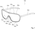
- the Figure 1 shows a sunglasses device 10a.
- the sunglasses device 10a is formed by sunglasses.
- the sunglasses device 10a is formed by mono-lens sunglasses.
- the sunglasses device 10a it is also conceivable for the sunglasses device 10a to be designed as a sun visor, ski goggles, motorcycle goggles, safety goggles, or the like.
- the sunglasses device 10a automatically darkens depending on solar radiation. In principle, however, another design of the sunglasses device 10a that would appear appropriate to a person skilled in the art would also be conceivable.
- the sunglasses device 10a is intended, at least in one operating state, to darken solar radiation on the eyes of a user.
- the sunglasses device 10a comprises at least one spectacle frame 52a.
- the spectacle frame 52a is formed by a spectacle frame.
- the spectacle frame 52a consists essentially of a metal material.
- the spectacle frame 52a has a surrounding frame 26a.
- the sunglasses device 10a has the surrounding frame 26a.
- the spectacle frame 52a has two spectacle temples 54a movably mounted on the surrounding frame 26a.
- the spectacle temples 54a are each provided to rest on the ears of the user.
- the frame 26a forms a nose cutout 56a for resting on a nose of the user.
- the surrounding frame 26a consists at least for the most part of a metal material.
- the frame 26a consists entirely of metal, in particular of a metal alloy.
- the surrounding frame 26a further has an upper frame leg 42a and a lower frame leg 44a.
- the frame 26a is designed free of an intermediate web between the upper frame leg 42a and the lower frame leg 44a.
- the upper frame leg 42a and the lower frame leg 44a are connected to one another only at the two connection points of the temples 54a.
- the frame 26a is designed in several parts, in particular in two parts, wherein the upper frame leg 42a and the lower frame leg 44a are detachably connected to one another by means of a screw connection.
- the upper frame leg 42a and the lower frame leg 44a are screwed together at a connection point of the temples 54a.
- the frame 26a to be formed in one piece, in particular in one piece.
- the nose pad holders are formed in one piece with the lower frame leg 44a.
- the sunglasses device 10a has a mono-lens element 12a.
- the mono-lens element 12a extends from a first viewing area 14a over the nose bridge area 16a into a second viewing area 18a of the sunglasses device 10a.
- the mono-lens element 12a is formed in one piece, in particular as a single part.
- the circumferential frame 26a surrounds an outer edge 62a of the mono-lens element 12a.
- the mono-lens element 12a consists largely of a plastic.
- the mono-lens element 12a consists at least partially of glass, polycarbonate, cellulose triacetate, or another suitable plastic.
- the mono-lens element 12a is made of polycarbonate.
- the sunglasses device 10a has exactly one mono-lens element 12a, wherein in particular no further lens element is provided.
- the mono-lens element 12a is formed to be transparent, wherein the mono-lens element 12a can have a tint and/or mirror coating.
- the mono-pane element 12a is transparent in the first viewing area 14a, in the nose bridge area 16a, and in the second viewing area 18a.
- the mono-pane element 12a has a constant thickness. However, a non-constant thickness of the mono-pane element 12a would also be conceivable. The thickness is not necessarily constant. By using a mono-pane element 12a with different thicknesses In particular, optical distortions can be corrected.
- the mono-lens element 12a is tapered in a transverse direction in the nose bridge region 16a.
- the mono-lens element 12a has a nose cutout in the nose bridge region 16a that follows the nose cutout 56a of the frame 26a.
- the mono-pane element 12a is directly connected to the surrounding frame 26a in a form-fitting manner.
- the mono-pane element 12a is connected to the surrounding frame 26a in a form-fitting manner at least in the nose bridge region 16a.
- the mono-pane element 12a has at least one form-fitting element 28a, 30a.
- the mono-pane element 12a has, for example, two form-fitting elements 28a, 30a in the nose bridge region 16a, with a first form-fitting element 28a facing the upper frame leg 42a and a second form-fitting element 30a facing the lower frame leg 44a.
- the frame 26a has at least one form-fitting element 32a, 34a corresponding to the at least one form-fitting element 28a, 30a of the mono-pane element 12a.
- the frame 26a has, for example, two form-locking elements 32a, 34a, wherein a first form-locking element 32a is arranged in the nose bridge area 16a on the upper frame leg 42a and a second form-locking element 34a is arranged in the nose bridge area 16a on the lower frame leg 44a.
- the form-locking elements 32a, 34a of the frame 26a are each formed by a form-locking extension which projects in the direction of the mono-disk element 12a.
- the form-locking elements 32a, 34a of the frame 26a are each integrally formed, in particular by welding, onto the upper frame leg 42a and the lower frame leg 44a, respectively.
- the form-locking elements 32a, 34a of the frame 26a are each formed by a dovetail extension with rounded corners.
- Another design of the form-locking elements 32a, 34a would also be conceivable, one that would appear appropriate to a person skilled in the art.
- the form-locking elements 28a, 30a of the mono-disk element 12a are each provided to partially encompass the form-locking extension.
- the form-locking elements 28a, 30a of the mono-disk element 12a each encompass one of the form-locking elements 32a, 34a of the frame 26a in a plane parallel to the main extension plane of the mono-disk element 12a.
- the form-locking elements 28a, 30a of the mono-disk element 12a each form a rounded dovetail recess, which is designed to correspond to the shape of the form-locking elements 32a, 34a of the frame 26a.
- Form-locking elements 28a, 30a of the mono-disk element 12a each have protruding lugs on both sides of the dovetail recess, which delimit and form the dovetail recess.
- the lugs of the form-locking elements 28a, 30a protrude beyond a regular contour of the mono-disk element 12a.
- the lugs of the form-locking elements 28a, 30a protrude from a regular contour of the mono-disk element 12a in a plane parallel to a main extension plane of the mono-disk element 12a.
- the form-locking elements 28a, 30a of the mono-disk element 12a are arranged on an outer edge 62a of the mono-disk element 12a in the nose bridge area 16a ( Figure 3 ).
- the sunglasses device 10a has an intermediate frame 46a, which is at least partially arranged between the frame 26a and the mono-lens element 12a.
- the intermediate frame 46a is intended to create a transition between the mono-lens element 12a and the surrounding frame 26a.
- the intermediate frame 46a has covering functions.
- the intermediate frame 46a is intended to at least partially cover, in particular partially enclose, electronics, in particular a control and/or regulating unit 60a of an optical sun protection filter 20a.
- the intermediate frame 46a is intended to cover an outer edge 64a of a liquid crystal cell 22a of the optical sun protection filter 20a.
- the intermediate frame 46a is designed to be circumferential.
- the intermediate frame 46a surrounds the mono-lens element 12a.
- the intermediate frame 46a extends along an outer edge 62a of the mono-lens element 12a.
- the intermediate frame 46a extends along the outer edge 62a of the mono-disk element 12a.
- the intermediate frame 46a is held in a form-fitting manner between the surrounding frame 26a and the mono-pane element 12a.
- the intermediate frame 46a rests against an inner side of the surrounding frame 26a.
- the intermediate frame 46a is formed in one piece.
- the intermediate frame 46a has an upper intermediate frame leg 66a, which extends substantially parallel to the upper frame leg 42a of the frame 26a, and a lower intermediate frame leg 68a, which extends substantially parallel to the lower frame leg 44a of the frame 26a.
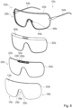
- the intermediate frame 46a consists at least for the most part of a plastic, in particular a polymer ( Figure 2 , 4 ).
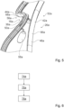
- the intermediate frame 46a defines at least one recess 48a, 50a in the nose bridge region 16a.
- the intermediate frame 46a defines two recesses 48a, 50a in the nose bridge region 16a, wherein a first recess 48a is arranged in the nose bridge region 16a in the upper intermediate frame leg 66a facing the upper frame leg 42a of the frame 26a, and a second recess 50a is arranged in the nose bridge region 16a in the lower intermediate frame leg 68a facing the lower frame leg 44a of the frame 26a.
- the recesses 48a, 50a are each formed by a through-hole materially completely enclosed by the intermediate frame 46a in at least one plane.
- the recesses 48a, 50a each extend parallel to the main extension plane of the mono-lens element 12a through the intermediate frame 46a.
- the recesses 48a, 50a are each materially completely enclosed by the intermediate frame 46a in a plane perpendicular to the main extension plane of the mono-lens element 12a.
- the recesses 48a, 50a are completely concealed from the outside in an assembled state of the sunglasses device 10a.
- the recesses 48a, 50a are each formed by a longitudinal slot.
- the recesses 48a, 50a each extend from the mono-lens element 12a through the intermediate frame 46a to the circumferential frame 26a.
- the recesses 48a, 50a each extend parallel to the main extension plane of the mono-lens element 12a through the intermediate frame 46a ( Figure 4 , 5 ).
- the form-locking elements 32a, 34a of the frame 26a and the form-locking elements 28a, 30a of the mono-disk element 12a each extend at least partially through one of the recesses 48a, 50a of the intermediate frame 46a.
- the form-locking elements 32a, 34a of the frame 26a extend at least partially through the recesses 48a, 50a of the intermediate frame 46a to the respective corresponding form-locking element 28a, 30a of the mono-disk element 12a.
- the first form-locking element 32a of the frame 26a extends through the first recess 48a of the intermediate frame 46a to the first form-locking element 28a of the mono-disk element 12a.
- the first form-locking element 28a of the mono-disk element 12a partially projects into the first recess 48a of the intermediate frame 46a.
- the second form-locking element 34a of the frame 26a extends through the second recess 50a of the intermediate frame 46a to the second form-locking element 30a of the mono-disk element 12a.
- the second form-locking element 30a of the mono-disk element 12a partially projects into the second recess 50a of the intermediate frame 46a.
- the form-locking elements 28a, 30a, 32a, 34a are connected to one another through the recesses 48a, 50a.
- the sunglasses device 10a comprises at least one optical sun protection filter 20a arranged on the mono-lens element 12a.
- the light transmittance of the optical sun protection filter 20a is adjustable.
- the optical sun protection filter 20a is substantially transparent, with a transmission of the optical sun protection filter 20a being at least partially electrically variable.
- the optical sun protection filter 20a has at least one liquid crystal cell 22a.
- the liquid crystal cell 22a is arranged on the mono-lens element 12a.
- the liquid crystal cell 22a of the optical sun protection filter 20a is integrally connected to the mono-lens element 12a.
- the liquid crystal cell 22a of the optical sun protection filter 20a is adhesively bonded to the mono-lens element 12a.
- the liquid crystal cell 22a is arranged on an inner side of the mono-lens element 12a, which inner side faces a user when worn.
- the liquid crystal cell 22a is constructed in the form of a multilayer film.
- the liquid crystal cell 22a of the optical sun protection filter 20a is arranged at a defined constant distance from an edge, in particular an outer edge 62a of the mono-pane element 12a.
- the distance in a nose bridge region 16a is sectionally spaced from an arrangement of a sensor unit 24a of the optical sun protection filter 20a. enlarged.
- the liquid crystal cell 22a is arranged with the outer edge 64a circumferentially at a substantially constant distance from the outer edge 62a of the mono-pane element 12a.
- the liquid crystal cell 22a is recessed relative to the outer edge 62a of the mono-pane element 12a.
- a minimum distance between the outer edge 62a of the mono-pane element 12a and the outer edge 64a of the liquid crystal cell 22a is in particular at least 1 mm, preferably at least 2 mm and particularly preferably a maximum of 3 mm.
- the minimum distance is constant circumferentially, wherein the minimum distance between the outer edge 62a of the mono-pane element 12a and the outer edge 64a of the liquid crystal cell 22a is a maximum of 10 mm, preferably a maximum of 8 mm and particularly preferably a maximum of 5 mm.
- the intermediate frame 46a circumferentially conceals the recessed outer edge 64a of the liquid crystal cell 22a of the optical sun protection filter 20a.
- the liquid crystal cell 22a has a liquid crystal layer whose transmission can be switched.
- the liquid crystal cell 22a of the optical sun protection filter 20a is formed by a plastic liquid crystal cell.
- the liquid crystal cell 22a consists of several layers. The number of layers is merely exemplary and can fundamentally vary.
- the liquid crystal cell 22a is formed by a TN liquid crystal cell.
- the liquid crystal cell 22a is therefore based on twisted nematic technology. In principle, however, another design of the liquid crystal cell 22a that would appear appropriate to a person skilled in the art would also be conceivable.
- the liquid crystal layer is formed by a translucent liquid crystal layer.
- the liquid crystal layer has a liquid crystal layer. A plurality of crystal molecules and spacers are located in the liquid crystal layer.
- a polyimide layer is arranged on each side of the liquid crystal layer.
- the polyimide layers serve in particular to align the crystal molecules.
- An electrode layer is arranged on each side of the polyimide layer facing away from the liquid crystal layer.
- the electrode layers are each formed by a transparent indium tin oxide layer.
- the optical sun protection filter 20a has the sensor unit 24a.
- the sensor unit 24a is provided for detecting solar radiation.
- Sensor unit 24a has a sensor surface 70a, which is provided for detecting solar radiation.
- the sensor unit 24a has one or more photodiodes, which are formed by a photocell. In principle, however, it would also be conceivable for the sensor unit 24a to have, for example, a solar cell. Furthermore, it would be conceivable, for example, for at least part of the sensor unit 24a, such as individual photodiodes, to be arranged as strips in a forehead area of the sunglasses device 10a.
- the sensor unit 24a is arranged below the upper frame leg 42a of the frame 26a behind the mono-pane element 12a.
- the sensor unit 24a is arranged concealed by the mono-pane element 12a.
- the optical sun protection filter 20a has a control and/or regulating unit 60a.
- the control and/or regulating unit 60a is provided to control the transmittance of the liquid crystal cell 22a depending on solar radiation.
- the control and/or regulating unit 60a is connected to the sensor unit 24a in a manner not further visibly shown.
- the control and/or regulating unit 60a is connected to the liquid crystal cell 22a of the optical sun protection filter 20a in a manner not further visibly shown.
- the control and/or regulating unit 60a is electrically connected to the electrode layers of the liquid crystal cell 22a.
- the control and/or regulating unit 60a and the sensor unit 24a are partially arranged in the intermediate frame 46a.
- the control and/or regulating unit 60a and the sensor unit 24a are partially arranged in the upper intermediate frame leg 66a of the intermediate frame 46a above the nose cutout 56a.
- the control and/or regulating unit 60a and the sensor unit 24a are arranged in a receiving area 72a of the intermediate frame 46a.
- the receiving area 72a is arranged in the upper intermediate frame leg 66a of the intermediate frame 46a.
- the upper intermediate frame leg 66a of the intermediate frame 46a is widened in the nose bridge area 16a.
- the receiving area 72a is delimited at the front by the mono-disk element 12a.
- the receiving area 72a of the intermediate frame 46a is formed by a recess.
- another arrangement of the control and/or regulating unit 60a and the sensor unit 24a that would appear sensible to a person skilled in the art would also be conceivable.
- the sensor unit 24a is provided to at least partially provide energy for controlling the liquid crystal cell 22a of the optical sun protection filter 20a.
- the sensor unit 24a is provided to completely provide energy for controlling the liquid crystal cell 22a of the optical sun protection filter 20a.
- the sensor unit 24a is provided to completely obtain the energy required to control the liquid crystal cell 22a of the optical sun protection filter 20a.
- the sunglasses device 10a is designed to be battery-free.
- Figure 6 shows a schematic flow diagram of a method for manufacturing, in particular assembling, the sunglasses device 10a.
- the method comprises a first method step 74a, in which the optical sun protection filter 20a is connected to the mono-pane element 12a.
- the liquid crystal cell 22a is glued to an inner side of the mono-pane element 12a.
- the intermediate frame 46a is arranged on the mono-pane element 12a.
- the intermediate frame 46a is slipped around the mono-pane element 12a, in particular by elastic deformation.
- a further method step 78a in which the circumferential frame 26a is mounted on the intermediate frame 46a and the mono-pane element 12a.
- the upper frame leg 42a and the lower frame leg 44a are placed from above and below onto the intermediate frame 46a and connected to one another.
- a connection can be made, for example, by welding, soldering, or screwing.
- the form-locking elements 32a, 34a of the frame 26a engage with the form-locking elements 28a, 30a of the mono-disc element 12a.
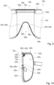
- the Figure 7 shows a sunglasses device 10b.
- the sunglasses device 10b is formed by sunglasses.
- the sunglasses device 10b is formed by mono-lens sunglasses.
- the sunglasses device 10b comprises at least one spectacle frame 52b.
- the spectacle frame 52b is formed by a spectacle frame.
- the spectacle frame 52b consists essentially of a metal material.
- the spectacle frame 52b has a surrounding frame 26b.
- the sunglasses device 10b has the surrounding frame 26b.
- the spectacle frame 52b has two spectacle temples 54b movably mounted on the surrounding frame 26b.
- the spectacle temples 54b are each provided to rest on the user's ears.
- the surrounding frame 26b further comprises an upper frame leg 42b and a lower frame leg 44b.
- the frame 26b is formed in a nose bridge region 16b free of an intermediate web between the upper frame leg 42b and the lower frame leg 44b.
- the sunglasses device 10b further comprises a mono-lens element 12b.
- the mono-lens element 12b extends from a first viewing area 14b across the nose bridge area 16b into a second viewing area 18b of the sunglasses device 10b.
- the mono-lens element 12b is formed in one piece, in particular in one part.
- the peripheral frame 26b surrounds an outer edge 62b of the mono-lens element 12b.
- the mono-disk element 12b is directly connected to the surrounding frame 26b in a form-fitting manner.
- the mono-disk element 12b is connected to the surrounding frame 26b in a form-fitting manner at least in the nose bridge area 16b.
- the mono-disk element 12b has at least one form-fitting element 28b, 30b.
- the mono-disk element 12b has, for example, two form-fitting elements 28b, 30b in the nose bridge area 16b, wherein the first form-fitting element 28b and the second form-fitting element 30b face the lower frame leg 44b.
- Frame 26b has at least one form-locking element 32b, 34b corresponding to the at least one form-locking element 28b, 30b of the mono-pane element 12b.
- the frame 26b has, for example, two form-locking elements 32b, 34b, wherein the first form-locking element 32b and the second form-locking element 34b are arranged in the nose bridge region 16b on the lower frame leg 44b.
- the form-locking elements 32b, 34b each delimit a form-locking recess 38b, 40b.
- the frame 26b has at least one form-locking recess 38b, 40b, which is intended to accommodate at least one form-locking element 28b, 30b of the mono-pane element 12b.
- the frame 26b has two form-locking recesses 38b, 40b, which are arranged on the nose cutout 56b and which are each provided to receive one of the form-locking elements 28b, 30b of the mono-disk element 12b.
- the form-locking elements 28b, 30b of the mono-disk element 12b are each formed by a locking lug, which is provided to engage in one of the form-locking recesses 38b, 40b of the frame 26b ( Figure 9 , 11 ).
- the sunglasses device 10b comprises at least one optical sun protection filter 20b arranged on the mono-pane element 12b.
- the light transmittance of the optical sun protection filter 20b is adjustable.
- the optical sun protection filter 20b has at least one liquid crystal cell 22b.
- the liquid crystal cell 22b is arranged on the mono-pane element 12b.
- the liquid crystal cell 22b of the optical sun protection filter 20b is integrally connected to the mono-pane element 12b.
- the liquid crystal cell 22b of the optical sun protection filter 20b is adhesively bonded to the mono-pane element 12b.
- the liquid crystal cell 22b of the optical sun protection filter 20b is defined by a arranged at a constant distance from an edge, in particular an outer edge 62b of the mono-pane element 12b.
- the distance is increased in sections in a nose bridge region 16b relative to an arrangement of a sensor unit 24b of the optical sun protection filter 20b.
- the liquid crystal cell 22b is arranged with the outer edge 64b circumferentially at a substantially constant distance from the outer edge 62b of the mono-pane element 12b.
- the liquid crystal cell 22b is recessed relative to the outer edge 62b of the mono-pane element 12b.
- the liquid crystal cell 22b has a circumferential seal 82b.
- the seal 82b serves in particular to protect the liquid crystal cell 22b.
- the optical sun protection filter 20b has the sensor unit 24b.
- the sensor unit 24b is provided for detecting solar radiation.
- the optical sun protection filter 20b has a control and/or regulating unit 60b.
- the sunglasses device 10b has a cover 80b for covering the control and/or regulating unit 60b and the sensor unit 24b from a front side.
Landscapes
- Physics & Mathematics (AREA)
- Health & Medical Sciences (AREA)
- Ophthalmology & Optometry (AREA)
- General Physics & Mathematics (AREA)
- Optics & Photonics (AREA)
- General Health & Medical Sciences (AREA)
- Eyeglasses (AREA)
Priority Applications (2)
| Application Number | Priority Date | Filing Date | Title |
|---|---|---|---|
| EP23200979.5A EP4530704A1 (fr) | 2023-09-29 | 2023-09-29 | Dispositif de lunettes de soleil |
| PCT/EP2024/077341 WO2025068548A1 (fr) | 2023-09-29 | 2024-09-27 | Dispositif de lunettes de soleil |
Applications Claiming Priority (1)
| Application Number | Priority Date | Filing Date | Title |
|---|---|---|---|
| EP23200979.5A EP4530704A1 (fr) | 2023-09-29 | 2023-09-29 | Dispositif de lunettes de soleil |
Publications (1)
| Publication Number | Publication Date |
|---|---|
| EP4530704A1 true EP4530704A1 (fr) | 2025-04-02 |
Family
ID=88238053
Family Applications (1)
| Application Number | Title | Priority Date | Filing Date |
|---|---|---|---|
| EP23200979.5A Pending EP4530704A1 (fr) | 2023-09-29 | 2023-09-29 | Dispositif de lunettes de soleil |
Country Status (2)
| Country | Link |
|---|---|
| EP (1) | EP4530704A1 (fr) |
| WO (1) | WO2025068548A1 (fr) |
Citations (7)
| Publication number | Priority date | Publication date | Assignee | Title |
|---|---|---|---|---|
| DE3038032A1 (de) * | 1979-10-13 | 1981-04-23 | Mamoru Fukui Murakami | Befestigungsvorrichtung fuer ein brillenglas |
| DE8800762U1 (de) * | 1988-01-22 | 1988-03-24 | Hornig, Wolfgang, Dr., 6902 Sandhausen | Schutzbrille |
| WO2017051093A1 (fr) * | 2015-09-24 | 2017-03-30 | Essilor International (Compagnie Generale D'optique) | Monture électronique pour dispositif optique et dispositif optique comportant une telle monture |
| WO2019153084A1 (fr) * | 2018-02-07 | 2019-08-15 | Brent Sheldon | Ensemble lunettes flexible |
| CN110231718A (zh) * | 2019-02-13 | 2019-09-13 | 董达智 | 嵌入式安装电子部件的力学光学双重防护眼镜片的护目镜 |
| WO2022123423A1 (fr) * | 2020-12-07 | 2022-06-16 | Out Of S.R.L. | Masque de protection oculaire pour la pratique de sports d'hiver |
| WO2023047271A1 (fr) * | 2021-09-21 | 2023-03-30 | Out Of S.R.L. | Lunettes de protection à cristaux liquides de type gh et cadre structural de recouvrement |
-
2023
- 2023-09-29 EP EP23200979.5A patent/EP4530704A1/fr active Pending
-
2024
- 2024-09-27 WO PCT/EP2024/077341 patent/WO2025068548A1/fr not_active Ceased
Patent Citations (7)
| Publication number | Priority date | Publication date | Assignee | Title |
|---|---|---|---|---|
| DE3038032A1 (de) * | 1979-10-13 | 1981-04-23 | Mamoru Fukui Murakami | Befestigungsvorrichtung fuer ein brillenglas |
| DE8800762U1 (de) * | 1988-01-22 | 1988-03-24 | Hornig, Wolfgang, Dr., 6902 Sandhausen | Schutzbrille |
| WO2017051093A1 (fr) * | 2015-09-24 | 2017-03-30 | Essilor International (Compagnie Generale D'optique) | Monture électronique pour dispositif optique et dispositif optique comportant une telle monture |
| WO2019153084A1 (fr) * | 2018-02-07 | 2019-08-15 | Brent Sheldon | Ensemble lunettes flexible |
| CN110231718A (zh) * | 2019-02-13 | 2019-09-13 | 董达智 | 嵌入式安装电子部件的力学光学双重防护眼镜片的护目镜 |
| WO2022123423A1 (fr) * | 2020-12-07 | 2022-06-16 | Out Of S.R.L. | Masque de protection oculaire pour la pratique de sports d'hiver |
| WO2023047271A1 (fr) * | 2021-09-21 | 2023-03-30 | Out Of S.R.L. | Lunettes de protection à cristaux liquides de type gh et cadre structural de recouvrement |
Also Published As
| Publication number | Publication date |
|---|---|
| WO2025068548A1 (fr) | 2025-04-03 |
Similar Documents
| Publication | Publication Date | Title |
|---|---|---|
| EP3501464B1 (fr) | Cassette de protection pour un dispositif anti-reflet | |
| DE69722398T2 (de) | Verbesserte einstärkenlinsen | |
| DE69813803T2 (de) | Linse mit starker Krümmung für eine Brille | |
| DE102019116904B4 (de) | Farbensehen-korrekturfilter und optische komponente | |
| EP3223067B1 (fr) | Dispositif de protection solaire | |
| DE3905041A1 (de) | Befestigungsanordnung | |
| DE3016935A1 (de) | Multifokale brillenlinse mit gebietsweise gleitendem brechwert | |
| EP2978394A1 (fr) | Verre de vue pour lunettes ou visière de casque | |
| DE69837166T2 (de) | Brillengestell | |
| DE4106019A1 (de) | Lichtdurchlaessiges fenster und dessen elektro-optische steuerung | |
| DE2338400A1 (de) | Blendschutzbrille, insbesondere fuer kraftfahrer | |
| EP3958046B1 (fr) | Dispositif de protection solaire | |
| DE3933310A1 (de) | Befestigungsanordnung | |
| DE102022111995A1 (de) | Brillengläser zur Reduzierung der Progression von Myopie sowie Verfahren zur individuellen Brechnung oder Herstellung | |
| EP3258306B1 (fr) | Dispositif de protection solaire | |
| CH696021A5 (de) | Blendschutzvorrichtung. | |
| DE102012207384A1 (de) | Verfahren und Vorrichtung zur Herstellung einer Doppelsichtscheibe für eine Arbeitsschutzbrille | |
| WO2025068548A1 (fr) | Dispositif de lunettes de soleil | |
| EP3329887B1 (fr) | Filtre optique anti-éblouissement | |
| DE69210010T2 (de) | Elektro-optische vorrichtung mit einstellbarer durchlaessigkeit | |
| EP2666054B1 (fr) | Disque transparent avec revetement en miroirs | |
| DE19958331B4 (de) | Linse mit rückseitiger progressiver Brechkraftverteilung | |
| GB2277602A (en) | Opthalmic graduated photochromic lens | |
| DE19954376A1 (de) | Verstellbare Fokussierlinse | |
| DE2914479C2 (de) | Blendschutzbrille |
Legal Events
| Date | Code | Title | Description |
|---|---|---|---|
| PUAI | Public reference made under article 153(3) epc to a published international application that has entered the european phase |
Free format text: ORIGINAL CODE: 0009012 |
|
| STAA | Information on the status of an ep patent application or granted ep patent |
Free format text: STATUS: THE APPLICATION HAS BEEN PUBLISHED |
|
| AK | Designated contracting states |
Kind code of ref document: A1 Designated state(s): AL AT BE BG CH CY CZ DE DK EE ES FI FR GB GR HR HU IE IS IT LI LT LU LV MC ME MK MT NL NO PL PT RO RS SE SI SK SM TR |
|
| STAA | Information on the status of an ep patent application or granted ep patent |
Free format text: STATUS: REQUEST FOR EXAMINATION WAS MADE |
|
| 17P | Request for examination filed |
Effective date: 20251001 |
|
| STAA | Information on the status of an ep patent application or granted ep patent |
Free format text: STATUS: EXAMINATION IS IN PROGRESS |
|
| 17Q | First examination report despatched |
Effective date: 20260623 |