EP4530764A1 - Procédé de fonctionnement cyclique d'un logiciel de commande - Google Patents
Procédé de fonctionnement cyclique d'un logiciel de commande Download PDFInfo
- Publication number
- EP4530764A1 EP4530764A1 EP23200351.7A EP23200351A EP4530764A1 EP 4530764 A1 EP4530764 A1 EP 4530764A1 EP 23200351 A EP23200351 A EP 23200351A EP 4530764 A1 EP4530764 A1 EP 4530764A1
- Authority
- EP
- European Patent Office
- Prior art keywords
- time
- safety
- cycle
- diff
- ezq
- Prior art date
- Legal status (The legal status is an assumption and is not a legal conclusion. Google has not performed a legal analysis and makes no representation as to the accuracy of the status listed.)
- Granted
Links
Images

Classifications
-
- G—PHYSICS
- G05—CONTROLLING; REGULATING
- G05B—CONTROL OR REGULATING SYSTEMS IN GENERAL; FUNCTIONAL ELEMENTS OF SUCH SYSTEMS; MONITORING OR TESTING ARRANGEMENTS FOR SUCH SYSTEMS OR ELEMENTS
- G05B19/00—Program-control systems
- G05B19/02—Program-control systems electric
- G05B19/04—Program control other than numerical control, i.e. in sequence controllers or logic controllers
- G05B19/042—Program control other than numerical control, i.e. in sequence controllers or logic controllers using digital processors
- G05B19/0428—Safety, monitoring
-
- G—PHYSICS
- G05—CONTROLLING; REGULATING
- G05B—CONTROL OR REGULATING SYSTEMS IN GENERAL; FUNCTIONAL ELEMENTS OF SUCH SYSTEMS; MONITORING OR TESTING ARRANGEMENTS FOR SUCH SYSTEMS OR ELEMENTS
- G05B19/00—Program-control systems
- G05B19/02—Program-control systems electric
- G05B19/04—Program control other than numerical control, i.e. in sequence controllers or logic controllers
- G05B19/05—Programmable logic controllers, e.g. simulating logic interconnections of signals according to ladder diagrams or function charts
-
- G—PHYSICS
- G06—COMPUTING OR CALCULATING; COUNTING
- G06F—ELECTRIC DIGITAL DATA PROCESSING
- G06F1/00—Details not covered by groups G06F3/00 - G06F13/00 and G06F21/00
- G06F1/04—Generating or distributing clock signals or signals derived directly therefrom
- G06F1/14—Time supervision arrangements, e.g. real time clock
-
- G—PHYSICS
- G06—COMPUTING OR CALCULATING; COUNTING
- G06F—ELECTRIC DIGITAL DATA PROCESSING
- G06F7/00—Methods or arrangements for processing data by operating upon the order or content of the data handled
- G06F7/58—Random or pseudo-random number generators
- G06F7/588—Random number generators, i.e. based on natural stochastic processes
-
- G—PHYSICS
- G05—CONTROLLING; REGULATING
- G05B—CONTROL OR REGULATING SYSTEMS IN GENERAL; FUNCTIONAL ELEMENTS OF SUCH SYSTEMS; MONITORING OR TESTING ARRANGEMENTS FOR SUCH SYSTEMS OR ELEMENTS
- G05B2219/00—Program-control systems
- G05B2219/10—Plc systems
- G05B2219/15—Plc structure of the system
- G05B2219/15126—Calculate duration of cycle
-
- G—PHYSICS
- G05—CONTROLLING; REGULATING
- G05B—CONTROL OR REGULATING SYSTEMS IN GENERAL; FUNCTIONAL ELEMENTS OF SUCH SYSTEMS; MONITORING OR TESTING ARRANGEMENTS FOR SUCH SYSTEMS OR ELEMENTS
- G05B9/00—Safety arrangements
- G05B9/02—Safety arrangements electric
Definitions
- Today's common controllers are based on a hardware platform, a special electronic substructure, namely a programmable logic controller (PLC).
- PLC programmable logic controller
- These devices can still be dedicated control devices, such as multifunctional control platforms or industrial PCs, or edge computing platforms, which are increasingly found in the control networks of machine and plant operators, or even cloud computing platforms are used.
- the key is the abstraction of the hardware through containers or hypervisors.
- the soft PLC is then deployed using standard means or orchestrated via a tool – eliminating the need for installation as with software-based control.
- the invention lies in the field of safety-related controls, particularly as software.
- Programmable logic controllers must be designed in accordance with the requirements of the EN 61508 standard to ensure functional safety.
- Safety-related systems such as programmable logic controllers for critical processes, which contain electrical, electronic or programmable electronic components and whose failure poses a significant risk to humans or the environment, must be designed to ensure special safety. Examples of applications requiring increased safety include the following: nuclear power plants, control technology for systems with safety-related Importance, railway applications, telecommunications technology, signaling technology and data processing systems, chemical processes, but also, for example, small systems such as a punch for punching out sheet metal parts.
- the invention relates to a method for operating cycle-oriented control software for controlling a process, wherein the control software is executed within a runtime environment on a computer system, wherein in order to safeguard a system time of the computer system, a further safety time independent of the system time is queried in each cycle, wherein a first time difference is formed from the system time of the current cycle and the system time of the previous cycle and a second time difference is formed from the safety time of the current cycle and the safety time of the previous cycle and a comparison of the time differences is carried out with a predetermined tolerance, and in the event that the deviation of the time differences exceeds the tolerance, an error signal is generated.
- the elapsed time between the current and the last cycle was determined using the time difference between the two timers.
- the old time can also be subtracted from the new time.
- Soft-PLC virtual software control
- the task is solved by generating a random number when the runtime environment is started up. This random number is stored in a memory area and is added to the requested safety time each time the safety time is queried. At the beginning of a new cycle in the control software, the deviation of the time differences is calculated in a control block. In each cycle, the control block accesses the memory area and before calculating the time differences the random number is calculated again from the safety time in the control module. In the event that a new start-up of the runtime environment has taken place, this can be diagnosed by exceeding the tolerance, because the second time difference now has an offset which results from the safety time with a new random number of the current cycle and the safety time with the old random number of the previous cycle.
- the control software is operated as a safety control with a safety program and a standard user program and unwanted influences on the safety program can be detected.
- the cold start mechanism is carried out when the safety controller starts up after a power failure on the computer system.
- the cold start mechanism ensures that that the system always starts with initial values and not with the actual values of the last cycle. If the cold start mechanism has failed, this is detected when the difference is formed in the control module by exceeding the tolerance, which means that a failure of the cold start mechanism is detected.
- the safety time is read by a hardware component built into the computer system, specifically a network card. After the safety time is retrieved, it is converted to an integer value that simulates a standard frequency of 32.768 kHz.
- the task is also carried out by a computer system comprising a runtime environment, a cycle-oriented control software for controlling a process as a safety control to run, a random generator, a processor with a system time, a hardware component with an external time source for providing a security time, a memory area, designed to carry out the method according to one of claims 1 to 5.
- the computer system is designed as a multifunctional control platform or as an industrial PC or as an edge computing platform or as a cloud computing platform.
- control software is designed as a safety control with a safety program and a standard user program.
- the safety controller has a cold start mechanism which is designed to start up the safety controller after a power failure on the computer system, wherein the cold start mechanism is designed to pre-assign the safety controller with initial values and not with actual values of the last cycle, further comprising a control module designed to detect a failure of the cold start mechanism by forming a difference based on an exceeding of the tolerance.
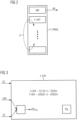
- a computer system 1 is shown, the computer system 1 can be, for example, an industrial PC or an edge computing platform.
- a hypervisor 7 is installed in the computer system 1, which enables an operating system 8, for example a Windows operating system, to be operated alongside a runtime environment FW.
- the runtime environment FW is designed to run a cycle-oriented control software SOFT-PLC for controlling a process as a safety controller.
- the control software SOFT-PLC is designed with a safety program F-PROG and with a standard user program S-PROG.
- F-CPU it is necessary that, in order to safeguard a system time SZ of the computer system 1, a further safety time eZQ that is independent of the system time SZ is queried in each cycle Z.
- a processor 5 of the computer system provides the system time SZ.
- the safety time eZQ is read by a hardware component 4 installed in the computer system 1, in particular a network card NIC.
- a query means 9 in the runtime environment FW ensures a continuous query of the safety time eZQ.
- a first time difference S-Diff is formed from the system time SZ of the previous cycle Zn-1 and a second time difference F-Diff is formed from the safety time eZQ of the current cycle and the safety time eZQ of the previous cycle Zn-1.
- a comparison of the time differences S-Diff, F-Diff with a predetermined tolerance TOL is performed, and in the event that the deviation of the time differences S-Diff, F-Diff exceeds the tolerance TOL, an error signal is generated.
- the elapsed time between the current and last cycle has now been determined using the time differences between both timers.
- a random number ZZ is generated when the runtime environment FW boots up. This random number ZZ is stored in memory area 2, and each time the safety time eZQ is queried, the random number ZZ is added to it.
- memory area 2 is accessed in a control block F-CRT, and before the time differences S-Diff, F-Diff are calculated, the random number ZZ is subtracted from the safety time eZQ in the control block F-CRT.
- the random number ZZ is generated by the random generator 3.
- the conversion means 10 ensures that the random number ZZ is added to the externally requested safety time eZQ.
- this solution adds the random number ZZ to the value of the safety time eZQ. This random number ZZ is generated once during each startup, for example, after a power failure.
- the random number ZZ is subtracted when calculating the difference between the times. If the cold start mechanism KM has failed, two different random numbers ZZ are used in cycle Z, once with the random number ZZ before “power off” and once with the new random number ZZ after "power on”. This means that the processing of the safety program F-PROG can be stopped because this is an indicator that the cold start mechanism KM has failed and the actual values AW have not been reset to the initial values IW.
- the computer system 1 also has additional reserved hardware 6 specifically for the safety controller F-CPU.
- FIG 3 shows the time calculation algorithm implemented in the F-CRT control module.
- the F-CRT control module receives as inputs the system time SZ, the random number ZZ from memory area 2, and the safety time eZQ converted using conversion means 10 to a safety time eZQ' to which the random number ZZ is added.
- the random number ZZ is subtracted from the safety time eZQ', resulting in the safety time eZQ (Zn).
- the differences S-Diff and F-Diff between the old and new times are then calculated. If the differences exceed a tolerance TOL, an error signal is generated.
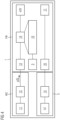
- FIG 4 shows a block diagram illustrating the different time formations.
- a system call 13 for example a Linux SysCall, is implemented on the network type register of the network card NIC.
- This system call 13 continuously fetches the safety time eZQ.
- the network card NIC provides a time base via a local time 11, whereby this time base is standardized to a standardized 64-bit counter via a standardization 12. This 64-bit counter is specified in nanoseconds.
- the random number generator 3 is also implemented in the runtime environment FW.
- the conversion means 10 receives the random number ZZ generated by the random number generator 3 and, with the help of a time converter 14, calculates the random number ZZ into the time.
- this calculated time is converted to a standard time of 32.768 kHz.
- the system time SZ of the processor 5 is made available to the runtime environment FW in the conventional manner via a base timer access 16.
- the system time SZ can be adjusted according to the specifications via a divider 15.
- the time required to control the process is made available to the safety program F-PROG and the user program S-PROG via a standard basic timer 17.
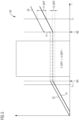
- FIG 5 A diagram 50 of the temporal progressions of the system time SZ and the safety time eZQ is shown.
- the system time SZ represented by the temporal progression 51
- the safety time eZQ' represented by the temporal progression 52
- the power fails.
- a processor or its system time SZ is designed to be retentive. This means that after the voltage returns or after the power failure ends at time NE (power on), the time continues to run with the last value. Since the behavior of the additionally acquired safety time eZQ is unknown or is generally not retentive, there is no defined behavior and no safe response can be made.
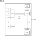
- the FIG 6 shows the basic sequence of events when starting a safety controller F-CPU.
- the cold start mechanism (KM) is executed.
- user data is deleted, as well as the current process image of the inputs and the current process image of the outputs.
- Retentive and non-retentive flags are deleted.
- Timers and counters are deleted. All DBs are initialized with initial values.
- peripheral outputs are switched to a safe state.
- the actual safety program F-PROG then starts from a safety OB F-OB.
- Different safety blocks F1, F2, F-CRT ... to Fn are called one after the other. All of these safety blocks ensure the functional safety required by the safety controller F-CPU.
- the control block F-CRT a random number ZZ is added to the safety time eZQ to protect the system time SZ. If the cold start mechanism KM fails, an old value in memory area 2 is used later for calculations and the failure of the cold start mechanism KM would be detected.
- a standard basic timer time 17 is provided in the standard user program S-PROG for calling an OB1.
Landscapes
- Engineering & Computer Science (AREA)
- Physics & Mathematics (AREA)
- General Physics & Mathematics (AREA)
- Theoretical Computer Science (AREA)
- Automation & Control Theory (AREA)
- General Engineering & Computer Science (AREA)
- Pure & Applied Mathematics (AREA)
- Mathematical Optimization (AREA)
- Mathematical Analysis (AREA)
- Computational Mathematics (AREA)
- Programmable Controllers (AREA)
- Debugging And Monitoring (AREA)
- Safety Devices In Control Systems (AREA)
Priority Applications (3)
| Application Number | Priority Date | Filing Date | Title |
|---|---|---|---|
| EP23200351.7A EP4530764B1 (fr) | 2023-09-28 | 2023-09-28 | Procédé de fonctionnement cyclique d'un logiciel de commande |
| CN202411343690.0A CN119717475A (zh) | 2023-09-28 | 2024-09-25 | 用于运行面向周期的控制软件的方法 |
| US18/898,065 US20250110465A1 (en) | 2023-09-28 | 2024-09-26 | Method for Operating a Segment of Cycle-Oriented Control Software |
Applications Claiming Priority (1)
| Application Number | Priority Date | Filing Date | Title |
|---|---|---|---|
| EP23200351.7A EP4530764B1 (fr) | 2023-09-28 | 2023-09-28 | Procédé de fonctionnement cyclique d'un logiciel de commande |
Publications (2)
| Publication Number | Publication Date |
|---|---|
| EP4530764A1 true EP4530764A1 (fr) | 2025-04-02 |
| EP4530764B1 EP4530764B1 (fr) | 2026-04-01 |
Family
ID=88236763
Family Applications (1)
| Application Number | Title | Priority Date | Filing Date |
|---|---|---|---|
| EP23200351.7A Active EP4530764B1 (fr) | 2023-09-28 | 2023-09-28 | Procédé de fonctionnement cyclique d'un logiciel de commande |
Country Status (3)
| Country | Link |
|---|---|
| US (1) | US20250110465A1 (fr) |
| EP (1) | EP4530764B1 (fr) |
| CN (1) | CN119717475A (fr) |
Citations (3)
| Publication number | Priority date | Publication date | Assignee | Title |
|---|---|---|---|---|
| EP2284771B1 (fr) | 2009-08-04 | 2013-04-17 | Siemens Aktiengesellschaft | Dispositif d'introduction dans un système informatique et système informatique |
| EP2241953B1 (fr) | 2009-04-17 | 2019-08-28 | Siemens Aktiengesellschaft | Procédé et dispositif de réalisation d'une fonction temporelle protégée contre l'erreur |
| DE102018120347A1 (de) * | 2018-08-21 | 2020-02-27 | Pilz Gmbh & Co. Kg | Automatisierungssystem zur Überwachung eines sicherheitskritischen Prozesses |
-
2023
- 2023-09-28 EP EP23200351.7A patent/EP4530764B1/fr active Active
-
2024
- 2024-09-25 CN CN202411343690.0A patent/CN119717475A/zh active Pending
- 2024-09-26 US US18/898,065 patent/US20250110465A1/en active Pending
Patent Citations (3)
| Publication number | Priority date | Publication date | Assignee | Title |
|---|---|---|---|---|
| EP2241953B1 (fr) | 2009-04-17 | 2019-08-28 | Siemens Aktiengesellschaft | Procédé et dispositif de réalisation d'une fonction temporelle protégée contre l'erreur |
| EP2284771B1 (fr) | 2009-08-04 | 2013-04-17 | Siemens Aktiengesellschaft | Dispositif d'introduction dans un système informatique et système informatique |
| DE102018120347A1 (de) * | 2018-08-21 | 2020-02-27 | Pilz Gmbh & Co. Kg | Automatisierungssystem zur Überwachung eines sicherheitskritischen Prozesses |
Also Published As
| Publication number | Publication date |
|---|---|
| CN119717475A (zh) | 2025-03-28 |
| EP4530764B1 (fr) | 2026-04-01 |
| US20250110465A1 (en) | 2025-04-03 |
Similar Documents
| Publication | Publication Date | Title |
|---|---|---|
| DE68922034T2 (de) | Systematische Wiederherstellung von übermässigen Programmspinschleifen in einer n-teiligen MP-Umgebung. | |
| EP3273314B1 (fr) | Commande programmable comportant un système de gestion | |
| WO2019219796A1 (fr) | Procédé pour simuler un système sur la base d'événements | |
| EP2513796B1 (fr) | Procédé permettant de faire fonctionner une unité de calcul | |
| EP2241953B1 (fr) | Procédé et dispositif de réalisation d'une fonction temporelle protégée contre l'erreur | |
| EP2284771A1 (fr) | Dispositif d'introduction dans un système informatique et système informatique | |
| DE19927657A1 (de) | Partitionierung und Überwachung von softwaregesteuerten Systemen | |
| EP0104490A2 (fr) | Méthode et dispositif pour la synchronisation de système de traitement de données | |
| DE3225712C2 (de) | Verfahren und Vorrichtung zur Funktionsprüfung von digitalen Rechnern | |
| EP4530764B1 (fr) | Procédé de fonctionnement cyclique d'un logiciel de commande | |
| DE102008043530B4 (de) | Maschinensteuerung und elektrische Maschine, insbesondere Industrieroboter | |
| WO2017080793A2 (fr) | Procédé de fonctionnement d'un processeur multicœur | |
| DE102021132235A1 (de) | Verfahren zur Simulation eines Steuergeräts auf einem Computer auf der Grundlage des AUTOSAR-Standards und Computer dafür | |
| EP0616274B1 (fr) | Méthode de synchronisation pour un système d'automatisation | |
| EP3841439B1 (fr) | Système d'automatisation de la surveillance d'un processus critique en matière de sécurité | |
| EP3311273A1 (fr) | Procédé et dispositif de sécurisation d'une structure de compteur de programme d'un système de processeur et de surveillance du traitement d'une demande d'interruption | |
| WO2006045754A1 (fr) | Procede, systeme d'exploitation et dispositif informatique pour executer un programme informatique | |
| EP1283471B1 (fr) | Unité commandée par programme | |
| DE102009000874A1 (de) | Verfahren zur Verbesserung der Analysierbarkeit von Softwarefehlern in einem Mikrocontroller | |
| DE102017219195A1 (de) | Verfahren zum gewährleisten eines betriebs eines rechners | |
| DE102007004794B4 (de) | Controllerbaustein mit einer Überwachung durch einen Watchdog | |
| EP2338111B1 (fr) | Procédé et dispositif pour tester un coeur de processeur dans une unité de calcul constituée d'au moins deux coeurs de processeur | |
| DE102016204965B4 (de) | Sicherheitssteuerung und Verfahren zum Betreiben einer Sicherheitssteuerung | |
| EP4679208A1 (fr) | Procédé de fonctionnement d'un logiciel de commande orienté cycle | |
| EP4557024A1 (fr) | Procédé de fonctionnement d'un logiciel de commande et dispositif doté d'un système informatique |
Legal Events
| Date | Code | Title | Description |
|---|---|---|---|
| PUAI | Public reference made under article 153(3) epc to a published international application that has entered the european phase |
Free format text: ORIGINAL CODE: 0009012 |
|
| STAA | Information on the status of an ep patent application or granted ep patent |
Free format text: STATUS: THE APPLICATION HAS BEEN PUBLISHED |
|
| AK | Designated contracting states |
Kind code of ref document: A1 Designated state(s): AL AT BE BG CH CY CZ DE DK EE ES FI FR GB GR HR HU IE IS IT LI LT LU LV MC ME MK MT NL NO PL PT RO RS SE SI SK SM TR |
|
| STAA | Information on the status of an ep patent application or granted ep patent |
Free format text: STATUS: REQUEST FOR EXAMINATION WAS MADE |
|
| 17P | Request for examination filed |
Effective date: 20250929 |
|
| GRAP | Despatch of communication of intention to grant a patent |
Free format text: ORIGINAL CODE: EPIDOSNIGR1 |
|
| STAA | Information on the status of an ep patent application or granted ep patent |
Free format text: STATUS: GRANT OF PATENT IS INTENDED |
|
| RIC1 | Information provided on ipc code assigned before grant |
Ipc: G05B 19/042 20060101AFI20251114BHEP Ipc: G05B 9/02 20060101ALI20251114BHEP Ipc: G06F 1/14 20060101ALI20251114BHEP |
|
| INTG | Intention to grant announced |
Effective date: 20251127 |
|
| GRAS | Grant fee paid |
Free format text: ORIGINAL CODE: EPIDOSNIGR3 |
|
| GRAA | (expected) grant |
Free format text: ORIGINAL CODE: 0009210 |
|
| STAA | Information on the status of an ep patent application or granted ep patent |
Free format text: STATUS: THE PATENT HAS BEEN GRANTED |
|
| AK | Designated contracting states |
Kind code of ref document: B1 Designated state(s): AL AT BE BG CH CY CZ DE DK EE ES FI FR GB GR HR HU IE IS IT LI LT LU LV MC ME MK MT NL NO PL PT RO RS SE SI SK SM TR |
|
| REG | Reference to a national code |
Ref country code: CH Ref legal event code: F10 Free format text: ST27 STATUS EVENT CODE: U-0-0-F10-F00 (AS PROVIDED BY THE NATIONAL OFFICE) Effective date: 20260401 Ref country code: GB Ref legal event code: FG4D Free format text: NOT ENGLISH |
|
| REG | Reference to a national code |
Ref country code: DE Ref legal event code: R096 Ref document number: 502023003567 Country of ref document: DE |
|
| REG | Reference to a national code |
Ref country code: IE Ref legal event code: FG4D Free format text: LANGUAGE OF EP DOCUMENT: GERMAN |