EP4530975A1 - Détermination d'indices hémodynamiques - Google Patents
Détermination d'indices hémodynamiques Download PDFInfo
- Publication number
- EP4530975A1 EP4530975A1 EP23465537.1A EP23465537A EP4530975A1 EP 4530975 A1 EP4530975 A1 EP 4530975A1 EP 23465537 A EP23465537 A EP 23465537A EP 4530975 A1 EP4530975 A1 EP 4530975A1
- Authority
- EP
- European Patent Office
- Prior art keywords
- lumen radius
- coronary arteries
- lumen
- profile
- determining
- Prior art date
- Legal status (The legal status is an assumption and is not a legal conclusion. Google has not performed a legal analysis and makes no representation as to the accuracy of the status listed.)
- Pending
Links
Images



Classifications
-
- A—HUMAN NECESSITIES
- A61—MEDICAL OR VETERINARY SCIENCE; HYGIENE
- A61B—DIAGNOSIS; SURGERY; IDENTIFICATION
- A61B6/00—Apparatus or devices for radiation diagnosis; Apparatus or devices for radiation diagnosis combined with radiation therapy equipment
- A61B6/50—Apparatus or devices for radiation diagnosis; Apparatus or devices for radiation diagnosis combined with radiation therapy equipment specially adapted for specific body parts; specially adapted for specific clinical applications
- A61B6/504—Apparatus or devices for radiation diagnosis; Apparatus or devices for radiation diagnosis combined with radiation therapy equipment specially adapted for specific body parts; specially adapted for specific clinical applications for diagnosis of blood vessels, e.g. by angiography
-
- G—PHYSICS
- G06—COMPUTING OR CALCULATING; COUNTING
- G06T—IMAGE DATA PROCESSING OR GENERATION, IN GENERAL
- G06T7/00—Image analysis
- G06T7/0002—Inspection of images, e.g. flaw detection
- G06T7/0012—Biomedical image inspection
-
- A—HUMAN NECESSITIES
- A61—MEDICAL OR VETERINARY SCIENCE; HYGIENE
- A61B—DIAGNOSIS; SURGERY; IDENTIFICATION
- A61B6/00—Apparatus or devices for radiation diagnosis; Apparatus or devices for radiation diagnosis combined with radiation therapy equipment
- A61B6/50—Apparatus or devices for radiation diagnosis; Apparatus or devices for radiation diagnosis combined with radiation therapy equipment specially adapted for specific body parts; specially adapted for specific clinical applications
- A61B6/503—Apparatus or devices for radiation diagnosis; Apparatus or devices for radiation diagnosis combined with radiation therapy equipment specially adapted for specific body parts; specially adapted for specific clinical applications for diagnosis of the heart
-
- G—PHYSICS
- G06—COMPUTING OR CALCULATING; COUNTING
- G06T—IMAGE DATA PROCESSING OR GENERATION, IN GENERAL
- G06T7/00—Image analysis
- G06T7/0002—Inspection of images, e.g. flaw detection
- G06T7/0012—Biomedical image inspection
- G06T7/0014—Biomedical image inspection using an image reference approach
- G06T7/0016—Biomedical image inspection using an image reference approach involving temporal comparison
-
- G—PHYSICS
- G06—COMPUTING OR CALCULATING; COUNTING
- G06T—IMAGE DATA PROCESSING OR GENERATION, IN GENERAL
- G06T7/00—Image analysis
- G06T7/10—Segmentation; Edge detection
- G06T7/11—Region-based segmentation
-
- G—PHYSICS
- G06—COMPUTING OR CALCULATING; COUNTING
- G06T—IMAGE DATA PROCESSING OR GENERATION, IN GENERAL
- G06T7/00—Image analysis
- G06T7/30—Determination of transform parameters for the alignment of images, i.e. image registration
- G06T7/33—Determination of transform parameters for the alignment of images, i.e. image registration using feature-based methods
- G06T7/337—Determination of transform parameters for the alignment of images, i.e. image registration using feature-based methods involving reference images or patches
-
- G—PHYSICS
- G16—INFORMATION AND COMMUNICATION TECHNOLOGY [ICT] SPECIALLY ADAPTED FOR SPECIFIC APPLICATION FIELDS
- G16H—HEALTHCARE INFORMATICS, i.e. INFORMATION AND COMMUNICATION TECHNOLOGY [ICT] SPECIALLY ADAPTED FOR THE HANDLING OR PROCESSING OF MEDICAL OR HEALTHCARE DATA
- G16H30/00—ICT specially adapted for the handling or processing of medical images
- G16H30/40—ICT specially adapted for the handling or processing of medical images for processing medical images, e.g. editing
-
- G—PHYSICS
- G16—INFORMATION AND COMMUNICATION TECHNOLOGY [ICT] SPECIALLY ADAPTED FOR SPECIFIC APPLICATION FIELDS
- G16H—HEALTHCARE INFORMATICS, i.e. INFORMATION AND COMMUNICATION TECHNOLOGY [ICT] SPECIALLY ADAPTED FOR THE HANDLING OR PROCESSING OF MEDICAL OR HEALTHCARE DATA
- G16H50/00—ICT specially adapted for medical diagnosis, medical simulation or medical data mining; ICT specially adapted for detecting, monitoring or modelling epidemics or pandemics
- G16H50/20—ICT specially adapted for medical diagnosis, medical simulation or medical data mining; ICT specially adapted for detecting, monitoring or modelling epidemics or pandemics for computer-aided diagnosis, e.g. based on medical expert systems
-
- G—PHYSICS
- G16—INFORMATION AND COMMUNICATION TECHNOLOGY [ICT] SPECIALLY ADAPTED FOR SPECIFIC APPLICATION FIELDS
- G16H—HEALTHCARE INFORMATICS, i.e. INFORMATION AND COMMUNICATION TECHNOLOGY [ICT] SPECIALLY ADAPTED FOR THE HANDLING OR PROCESSING OF MEDICAL OR HEALTHCARE DATA
- G16H50/00—ICT specially adapted for medical diagnosis, medical simulation or medical data mining; ICT specially adapted for detecting, monitoring or modelling epidemics or pandemics
- G16H50/30—ICT specially adapted for medical diagnosis, medical simulation or medical data mining; ICT specially adapted for detecting, monitoring or modelling epidemics or pandemics for calculating health indices; for individual health risk assessment
-
- G—PHYSICS
- G06—COMPUTING OR CALCULATING; COUNTING
- G06T—IMAGE DATA PROCESSING OR GENERATION, IN GENERAL
- G06T2207/00—Indexing scheme for image analysis or image enhancement
- G06T2207/10—Image acquisition modality
- G06T2207/10072—Tomographic images
- G06T2207/10081—Computed x-ray tomography [CT]
-
- G—PHYSICS
- G06—COMPUTING OR CALCULATING; COUNTING
- G06T—IMAGE DATA PROCESSING OR GENERATION, IN GENERAL
- G06T2207/00—Indexing scheme for image analysis or image enhancement
- G06T2207/30—Subject of image; Context of image processing
- G06T2207/30004—Biomedical image processing
- G06T2207/30048—Heart; Cardiac
-
- G—PHYSICS
- G06—COMPUTING OR CALCULATING; COUNTING
- G06T—IMAGE DATA PROCESSING OR GENERATION, IN GENERAL
- G06T2207/00—Indexing scheme for image analysis or image enhancement
- G06T2207/30—Subject of image; Context of image processing
- G06T2207/30004—Biomedical image processing
- G06T2207/30101—Blood vessel; Artery; Vein; Vascular
-
- G—PHYSICS
- G06—COMPUTING OR CALCULATING; COUNTING
- G06T—IMAGE DATA PROCESSING OR GENERATION, IN GENERAL
- G06T7/00—Image analysis
- G06T7/60—Analysis of geometric attributes
- G06T7/62—Analysis of geometric attributes of area, perimeter, diameter or volume
Definitions
- Various examples of the disclosure generally relate to angiography.
- Various examples specifically relate to processing multiple cardiac images depicting a portion of coronary arteries within an anatomical region of interest to determine respective values of at least one hemodynamic index at a location of the portion of the coronary arteries.
- FFR Fractional Flow Reserve
- FFR is a hemodynamic index to determine the hemodynamic significance of a given epicardial coronary stenosis. It can be defined as the ratio of maximal achievable blood flow in a myocardial bed in the presence of an epicardial stenosis to the theoretical normal maximal flow in the same myocardial distribution.
- FFR is measured invasively using angiography. During such an invasive procedure, a contrast agent is injected through a catheter and into coronary arteries to make them easier to see. However, exposure to the contrast agent may cause kidney diseases or allergic reactions. Additionally, for an accurate measurement, FFR is measured when blood flow is at its highest, and thereby certain medicine, e.g., adenosine or papaverine is used to increase the blood flow. Such medicine may incur health risks.
- CFD computational fluid dynamics
- ML machine learning
- An exemplary processing pipeline may comprise multiple image-based artificial intelligence (AI) modules and some or all of the AI modules may process each frame of the one or more angiograms but without taking (temporal) information between different frames, e.g., neighboring frames, due to various reasons such as the complexity of the task, non-availability of multi-frame training data, or other challenges.
- AI artificial intelligence
- a computer-implemented method for processing multiple cardiac images comprises obtaining multiple cardiac images, each of the multiple cardiac images depicting a portion of coronary arteries within an anatomical region of interest.
- the method further comprises determining, based on each of the multiple cardiac images, a respective set of lumen radius measurements comprising multiple lumen radius measurements respectively associated with multiple locations of the portion of the coronary arteries.
- the method also comprises determining, based on the respective sets of lumen radius measurements, a maximum stenosis severity profile and a minimum stenosis severity profile associated with the portion of the coronary arteries .
- the method still further comprises determining a lumen radius profile associated with the portion of the coronary arteries based on the maximum stenosis severity profile and the minimum stenosis severity profile and determining, based on the lumen radius profile, a respective value for each of at least one hemodynamic index at a given location of the portion of the coronary arteries.
- the multiple cardiac images may comprise multiple frames of an angiogram which are acquired within a (single) cardiac cycle.
- a computing device comprising a processor and a memory. Upon loading and executing program code from the memory, the processor is configured to perform a method for processing multiple cardiac images.
- the method comprises obtaining multiple cardiac images, each of the multiple cardiac images depicting a portion of coronary arteries within an anatomical region of interest.
- the method further comprises determining, based on each of the multiple cardiac images, a respective set of lumen radius measurements comprising multiple lumen radius measurements respectively associated with multiple locations of the portion of the coronary arteries .
- the method also comprises determining, based on the respective sets of lumen radius measurements, a maximum stenosis severity profile and a minimum stenosis severity profile associated with the portion of the coronary arteries.
- the method still further comprises determining a lumen radius profile associated with the portion of the coronary arteries based on the maximum stenosis severity profile and the minimum stenosis severity profile and determining, based on the lumen radius profile, a respective value for each of at least one hemodynamic index at a given location of the portion of the coronary arteries.
- the method still further comprises determining a lumen radius profile associated with the portion of the coronary arteries based on the maximum stenosis severity profile and the minimum stenosis severity profile and determining, based on the lumen radius profile, a respective value for each of at least one hemodynamic index at a given location of the portion of the coronary arteries.
- a computer program product or a computer program or a computer-readable storage medium including program code is provided.
- the program code can be executed by at least one processor. Executing the program code causes the at least one processor to perform a method for processing multiple cardiac images.
- the method comprises obtaining multiple cardiac images, each of the multiple cardiac images depicting a portion of coronary arteries within an anatomical region of interest.
- the method further comprises determining, based on each of the multiple cardiac images, a respective set of lumen radius measurements comprising multiple lumen radius measurements respectively associated with multiple locations of the portion of the coronary arteries.
- the method also comprises determining, based on the respective sets of lumen radius measurements, a maximum stenosis severity profile and a minimum stenosis severity profile associated with the portion of the coronary arteries.
- the method still further comprises determining a lumen radius profile associated with the portion of the coronary arteries based on the maximum stenosis severity profile and the minimum stenosis severity profile and determining, based on the lumen radius profile, a respective value for each of at least one hemodynamic index at a given location of the portion of the coronary arteries.
- Some examples of the present disclosure generally provide for a plurality of circuits or other electrical devices . All references to the circuits and other electrical devices and the functionality provided by each are not intended to be limited to encompassing only what is illustrated and described herein. While particular labels may be assigned to the various circuits or other electrical devices disclosed, such labels are not intended to limit the scope of operation for the circuits and the other electrical devices. Such circuits and other electrical devices may be combined with each other and/or separated in any manner based on the particular type of electrical implementation that is desired.
- any circuit or other electrical device disclosed herein may include any number of microcontrollers, a graphics processor unit (GPU), integrated circuits, memory devices (e.g., FLASH, random access memory (RAM), read only memory (ROM), electrically programmable read only memory (EPROM), electrically erasable programmable read only memory (EEPROM), or other suitable variants thereof), and software which co-act with one another to perform operation(s) disclosed herein.
- any one or more of the electrical devices may be configured to execute a program code that is embodied in a non-transitory computer readable medium programmed to perform any number of the functions as disclosed.
- the at least one hemodynamic index may comprise at least one of a blood pressure, a blood flow rate, a fractional flow reserve, a heart rate, a cardiac index, a mean arterial pressure, a systemic vascular resistance index, a central venous pressure, and a central venous oxygen saturation.
- the multiple cardiac images may be obtained either during or after an angiography exam of the portion of coronary arteries within the anatomical region of interest.
- the processing may take place either during or after the angiography exam of the portion of coronary arteries, i.e., either real-time processing or post-processing is possible.
- the multiple cardiac images may be acquired at different time points of a cardiac cycle.
- the multiple cardiac images may be acquired during a cardiac cycle of 1 second using a C-arm X-ray machine with a frame rate of 10.
- the multiple cardiac images encapsulate the lumen information of the portion of the coronary arteries from multiple time points of a single cardiac cycle, e.g. , changes in respective lumen diameter values at different locations of the portion of the coronary arteries.
- the cardiac cycle is the performance of the human heart from the beginning of one heartbeat to the beginning of the next. It consists of two periods: one during which the heart muscle relaxes and refills with blood, called diastole, following a period of robust contraction and pumping of blood, called systole. After emptying, the heart relaxes and expands to receive another influx of blood returning from the lungs and other systems of the body, before again contracting to pump blood to the lungs and those systems. A normally performing heart must be fully expanded before it can efficiently pump again. Assuming a healthy heart and a typical rate of 70 to 75 beats per minute, each cardiac cycle, or heartbeat, takes about 0.8 second to complete the cycle.
- the multiple cardiac images may be obtained directly from an angiography device or from a database for storing the multiple cardiac images acquired by the angiography device, e.g. , a picture archiving and communication system (PACS).
- a picture archiving and communication system PACS
- the typical maximum frame rates found on an angiography device such as a C-arm X-ray machine are 8, 15, or 30. This means that during a single cardiac cycle of 0.8 second, 6, 12, or 24 frames can be acquired by a C-arm X-ray machine.
- the angiography device may comprise a C-arm X-ray machine, an intravascular ultrasound machine, an optical coherence tomography machine, or a coronary computed tomography angiography machine.
- FIG. 1 schematically illustrates aspects with respect to a C-arm machine 800.
- the C-arm machine 800 may be used for both angiography and fluoroscopy.
- the C-arm machine 800 is in neutral position P 0 . It is possible to manipulate the C-arm machine 800 to be in a rotated position deviating from the neutral position P 0 .
- the angle between the neutral position P0 and a specific rotated position is referred to as the angiography angle or the fluoroscopy angle.
- the C-arm machine 800 comprises a rotatable C arm 830 on which X-ray emission means 831 and X-ray detection means 832 may be mounted.
- the C arm 830 and thereby X-ray emission means 831 and X-ray detection means 832 are positioned to center around patient surface 840.
- X-ray emission means 831 may emit X-rays which may penetrate through a patient positioned on the patient surface 840.
- X-ray detection means 832 detects the X -rays emitted from X-ray emission means 831.
- X-ray emission means 831 and X-ray detection means 832 may also collectively be referred to as x-ray imaging means.
- the C arm 830 may be coupled to a C arm rotation unit 820.
- the C arm rotation unit 820 may be any motorized means configured to rotate the C arm 830 according to an angiography angel or a fluoroscopy angle.
- the C arm rotation unit 820 may be attached to and controlled by a C arm control until 810.
- the C arm control unit 810 may be any kind of circuitry capable of controlling C arm 830.
- the C arm control unit 810 may include a computing device.
- the C-arm machine 800 may further include a control panel 850 mounted onto a side surface of patient surface support 841.
- the control panel 850 may be used to control C arm 830 in order to guide medical specialists to pathological vessels.
- Fig. 1 does not show any connections between control panel 850 and C arm 830 to simplify the depiction of the exemplary C-arm machine 800.
- the connection may be wireless.
- the connection may be wired and may e.g. , be integrated into the ceiling of the room where the C-arm machine 800 is located.
- the C-arm machine 800 may also include a display 860.
- the display 860 may be used to display information to the medical specialist, such as real-time fluoroscopy image with an overlaid vessel roadmap image including a path to one or more pathological vessels, and/or a location of the pressure wire for measuring the at least one measurement associated with the at least one hemodynamic index. Further, the display 860 may be used to display vessel segmentation data included in overlaid vessel roadmap images, including labels for various vessel segments. In some examples, display 860 may be a touch screen, which may be used to toggle the display of the vessel segmentation data on and off.
- the C-arm machine 800 may be connectable to a database (not shown in FIG. 1 ), such as a PACS located within a local network of a hospital, for storing angiograms and/or measurements associated with the at least one hemodynamic index.
- a database such as a PACS located within a local network of a hospital, for storing angiograms and/or measurements associated with the at least one hemodynamic index.
- a name (e.g. , any one in the column "Abbreviation" in Table 1) of a specific segment of a coronary artery or of the entire coronary artery can be determined based on an anatomical region of interest of the angiography exam.
- an anatomical region of interest may comprise the left or right branch of the coronary vessel tree or a specific vessel section.
- the anatomical region of interest may be determined based on user input, or on a patient's electronic medical record included in a health information system. Additionally or optionally, the anatomical region of interest may be determined based on multiple predefined seed points.
- the portion of coronary arteries within the anatomical region of interest may be one or more segments of the coronary arteries of the heart.
- FIG. 2 schematically illustrates an exemplary 3D frontal view 200 of a heart and of coronary arteries.
- the segments of the coronary arteries in FIG. 2 are based on and numbered according to the vessel segmentation as proposed by the American Heart Association (AHA) and as amended by the Society of Cardiovascular Computed Tomography (SCCT).
- AHA American Heart Association
- SCCT Society of Cardiovascular Computed Tomography
- FIG. 2 also indicates the aortic valve 220.
- FIG. 3 illustrates aspects with respect to processing multiple cardiac images, each of which depicts a portion of coronary arteries i.e., the same portion of coronary arteries, e.g., LAD (i.e. , a combination of pLAD 206, mLAD 207, and dLAD 208) , or RCA (i.e., a combination of pRCA 201, mRCA 202, and dRCA 203) as shown in FIG. 2 , within an anatomical region of interest.
- LAD i.e. , a combination of pLAD 206, mLAD 207, and dLAD 208
- RCA i.e., a combination of pRCA 201, mRCA 202, and dRCA 203 as shown in FIG. 2 , within an anatomical region of interest.
- the multiple cardiac images are obtained either during or after an angiography exam and thereby the processing can be either real-time processing or post-processing.
- a respective set of lumen radius measurements is determined based on each of the multiple cardiac images and comprises multiple lumen radius measurements respectively associated with multiple locations of the portion of the coronary arteries.
- a maximum stenosis severity profile and a minimum stenosis severity profile associated with the portion of the coronary arteries are respectively determined based on the respective sets of lumen radius measurements.
- a lumen radius profile associated with the portion of the coronary arteries is determined based on the maximum stenosis severity profile and the minimum stenosis severity profile.
- a respective value for each of at least one hemodynamic index at a given location of the portion of the coronary arteries is determined based on the lumen radius profile. Details of the method 3000 are described below.
- Block 3100 obtaining multiple cardiac images, each of the multiple cardiac images depicting a portion of coronary arteries within an anatomical region of interest.
- the multiple cardiac images may comprise cardiac images acquired under different acquisition angles.
- the multiple cardiac images may be obtained directly from an angiography device, e.g., the C-arm machine 800 of FIG. 1 , under different acquisition angles.
- the multiple cardiac images may respectively depict different views of the same portion of coronary arteries to increase accuracy and robustness of the determination of the radius measurements.
- the true severity of a stenosis may need to be revealed by looking at it from multiple views, and multiple views can also help solve foreshortening-related issues.
- the multiple cardiac images may be obtained from a database for storing the multiple cardiac images acquired by the angiography device, e.g., a PACS.
- the multiple cardiac images may comprise cardiac images acquired using multi-phase coronary computed tomography angiography.
- the multiple cardiac images may be obtained from imaging data acquired using computed tomography angiography.
- a single cardiac image may correspond to a frame of an angiogram.
- FIG. 4 schematically illustrates multiple frames t1-f10 of an angiogram acquired at different time points t1-t10 and each of the multiple frames f1-f10 depicts the same portion C of the coronary arteries within an anatomical region of interest.
- the multiple frames f1-f10 may be acquired during a single cardiac cycle of 1 second using a C-arm X-ray machine with a frame rate of 10.
- the multiple frames f1-f10 encapsulate the lumen information of the portion C of the coronary arteries from multiple time points of a single cardiac cycle, e.g., changes in respective lumen diameter values at different locations of the portion C of the coronary arteries.
- said obtaining of the multiple cardiac images may comprise obtaining an angiogram acquired during an angiography exam of the anatomical region of interest and selecting, based on at least one pre-defined criterion, the multiple cardiac images among frames of the angiogram.
- Such pre-defined criterion may comprise at least one of the following:
- the multiple cardiac images may be selected from frames acquired in a single cardiac cycle, e.g., selecting 5 frames from the 10 frames f1-f10 acquired in a single cardiac cycle.
- the multiple cardiac images may be selected from frames acquired in different cardiac cycles.
- an acquired angiogram may comprise 100 frames acquired in 10 cardiac cycles, e.g., first to tenth cardiac cycles, and 10 frames, e.g., first to tenth frames, are acquired in each cardiac cycle.
- a first cardiac image may be selected from respective first frames acquired in respective cardiac cycles.
- a further or second cardiac image may be selected from respective second (or any one of the third to tenth) frames acquired in respective cardiac cycles.
- 10 cardiac images may be selected from frames acquired in 10 different cardiac cycles. Each one of the 10 cardiac images may be selected from respective frames acquired at the same time point within respective cardiac cycles.
- the first cardiac image, e.g., f1 among the 10 cardiac images may be selected from all the first frames respectively acquired in the first to tenth cardiac cycles;
- the second cardiac image, e.g., f2 among the 10 cardiac images may be selected from all the second frames respectively acquired in the first to tenth cardiac cycles; and so on.
- the method 3000 may further comprise determining the anatomical region of interest based on multiple predefined seed points.
- proximal seed points may comprise the catheter tip
- distal seed points may comprise one or more points selected on the main vessels or on side branches with significant stenoses .
- the portion of coronary arteries may be determined based on angulation information for acquiring the multiple cardiac images.
- the method 3000 may further comprise registering the multiple cardiac images.
- proximal and distal seed points may be co-registered across the multiple cardiac images to ensure that they represent the same anatomical region of interest.
- said registration or co-registration may comprise applying a diffeomorphic registration algorithm, e.g., as disclosed in a non-patent literature - Ashburner, John. "A fast diffeomorphic image registration algorithm. " Neuroimage 38.1 (2007) : 95-113 ., on the vesselness maps extracted from each frame; using the obtained deformation fields to track each of the seed points from each frame onto all of the other frames; and aggregating the tracked seed points via a density-based clustering algorithm such as DB Scan (i.e., Density-based spatial clustering of applications with noise) , e.g., as disclosed in a non-patent literature - Hu, Lihua, et al. "KR-DBSCAN: A density-based clustering algorithm based on reverse nearest neighbor and influence space.” Expert Systems with Applications 186 (2021): 115763 .
- DB Scan i.e., Density-based spatial clustering of applications with noise
- the method 3000 may further comprise segmenting the anatomical region of interest across the multiple cardiac images, i.e., separating the anatomical region of interest from the background in each of the multiple cardiac images.
- Block 3200 determining, based on each of the multiple cardiac images, a respective set of lumen radius measurements comprising multiple lumen radius measurements respectively associated with multiple locations of the portion of the coronary arteries.
- the lumen radius measurements may be determined or calculated using any one of the existing techniques or algorithms related to quantitative coronary angiography.
- existing techniques or algorithms related to quantitative coronary angiography.
- non-patent literature - Garrone, Paolo, et al. Quantitative coronary angiography in the current era: principles and applications.” Journal of interventional cardiology 22.6 (2009): 527-536 .
- - provides a comprehensive and updated viewpoint on quantitative coronary angiography.
- various existing machine learning algorithms or image processing techniques can be used to determine the lumen radius measurements.
- FIG. 5 schematically illustrates one exemplary frame 1000 of an angiogram according to various examples.
- the frame 1000 may depict the portion C of coronary arteries as shown in FIG. 4 .
- a centerline 1100 is generated between the starting point 1101 and the ending point 1124 of the portion C of coronary arteries. Between the starting point 1101 and the ending point 1124, there are multiple location points 1102-1123.
- a respective lumen radius associated with such a location point may be measured or determined, and thereby a set of lumen radius measurements comprising the respective lumen radius at each of the location points 1101-1124 can be determined or calculated.
- each of the location points 1101-1124 it is also possible to determine multiple, e.g., 3, 4, 8, or even more, lumen radii based on multiple frames acquired using different acquisition angles and determine an average of the multiple lumen radii as the respective lumen radius for the respective set of lumen radius measurements.
- a respective set of lumen radius measurements comprising the respective lumen radius at each of the location points 1101-1124 can be determined or calculated.
- ten sets s1-s10 of lumen radius measurements can be determined respectively for the ten frames f1-f10, and each of the ten sets s1-s10 comprises lumen radius measurements respectively associated with the location points 1101-1124.
- a segmentation algorithm may be applied to the ten frames f1-f10, respectively, to separate the portion C of the coronary arteries from the background of the respective frame.
- said determining of the respective set of lumen radius measurements may comprise segmenting the portion C of the coronary arteries from the respective cardiac image of the multiple cardiac images f1-t10 and determining the respective set s1-s10 of the lumen radius measurements based on the respective segmented portion of the coronary arteries.
- the respective segmented portion of the coronary arteries may be co-registered along the centerline 1100 and/or based on landmarks detected in the respective frames f1-f10, e.g., bifurcations, stenoses, calcifications, and etc.
- Block 3300 determining, based on the respective sets of lumen radius measurements, a maximum stenosis severity profile and a minimum stenosis severity profile associated with the portion of the coronary arteries.
- the maximum stenosis severity profile and the minimum stenosis severity profile may be respectively determined based on local concavities and/or local convexities of multiple curves and each of the multiple curves may depict a respective relationship between a respective set of the lumen radius measurements and the multiple locations of the portion of the coronary arteries.
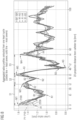
- respective curves (or original radius profiles) p1-p10 may be determined or plotted for each of the sets s1-s10 using interpolation such as linear interpolation, polynomial interpolation, spline interpolation, and/or mimetic interpolation.
- interpolation such as linear interpolation, polynomial interpolation, spline interpolation, and/or mimetic interpolation.
- the sets s1-s10 may be determined based on frames f1-f10 acquired in a single cardiac cycle or heart cycle.
- the x-axis of each curve may indicate respective distances (or 2D projection distances) between the catheter tip and each of the location points 1101-1124, and the y-axis may indicate respective lumen radii associated with the respective location points.
- the maximum stenosis severity profile and the minimum stenosis severity profile may be respectively determined based on local concavities or convexities of the respective curves p1-p10.
- the second derivatives at each of the location points 1101-1124 may be calculated for each of the respective curves p1-p10.
- the curve is concave up (also referred to as convex) at such a location point, meaning that the tangent line at such a location point lies below the curve; similarly, if the second derivative is negative the curve is concave down (also simply called concave) at such a location point, meaning that the tangent line at such a location point lies above the curve; if the second derivative changes sign, the curve will switch from concave down to concave up, or vice versa, and a point where this occurs is called an inflection point.
- the second derivatives may be computed via central finite differences.
- the respective sets s1-s10 of the lumen radius measurements may be not aligned.
- the respective sets s1-s10 of the lumen radius measurements may be warped before determining the maximum stenosis severity profile and the minimum stenosis severity profile.
- a dynamic time warping algorithm e.g. , as disclosed in a non-patent literature - Salvador, Stan, and Philip Chan. "Toward accurate dynamic time warping in linear time and space. " Intelligent Data Analysis 11.5 (2007) : 561-580 . - may be used for warping the respective sets sl-s10 of the lumen radius measurements.
- an optimal subsequence bijection algorithm such as that disclosed in a non-patent literature - Latecki, Longin Jan, et al. "Optimal subsequence bijection. " Seventh IEEE International Conference on Data Mining (ICDM 2007). IEEE, 2007 .
- said determining of the maximum stenosis severity profile and the minimum stenosis severity profile may comprise determining a reference set of the lumen radius measurements, aligning each of the respective sets of the lumen radius measurements with the reference set of the lumen radius measurements, and determining the maximum stenosis severity profile and the minimum stenosis severity profile based on the respective aligned sets of the lumen radius measurements.
- the reference set of the lumen radius measurements may be randomly or arbitrarily selected from the ten sets s1-s10 of the lumen radius measurements.
- s1 is selected as the reference set of the lumen radius measurements and the other sets s2-s10 can be respectively aligned with the reference set s1 using dynamic time warping algorithm, e.g., the dtw function of Matlab, i.e., executing dtw (s1, s2) , dtw (s1, s3) , dtw (sl,s4), ..., dtw (s1,s10).
- the dtw function of Matlab i.e., executing dtw (s1, s2) , dtw (s1, s3) , dtw (sl,s4), ..., dtw (s1,s10).
- said determining of the reference set of the lumen radius measurements may comprise selecting the set of the lumen radius measurements having the longest length as the reference set of the lumen radius measurements.
- the set of the lumen radius measurements having the longest length may be determined by sorting the respective sets of the lumen radius measurements based on respective lengths of the respective sets in descending or ascending order.
- each of the ten sets s1-s10 of the lumen radius measurements may be indicated as a row or column vector, and the length of a respective set corresponds to the number of elements or entries of the respective vector.
- said aligning of each of the respective sets of the lumen radius measurements with the reference set of the lumen radius measurements may comprise, for each of the respective unaligned sets of the lumen radius measurements, iteratively performing the following steps:
- the first sorted set i.e., the longest set, e.g., s5
- the second longest set e.g. , s2
- the reference set is updated based on the initial reference set s5 and the aligned set s2' of s2.
- the reference set may be determined or calculated based on either an element-wise average or an element-wise weighted average of s5 and s2'.
- the third longest set may be aligned with the updated reference set and then the reference set may be updated again by further considering the aligned set of the third longest set. I.e., said aligning and updating may be iteratively performed until the shortest set has been aligned.
- said aligning may be based on one or more anatomical landmarks within the anatomical region of interest.
- the one or more anatomical landmarks may be associated with the portion of coronary arteries, e.g., bifurcations, stenoses, calcifications, and etc.
- FIG. 7 schematically illustrates various exemplary curves respectively depicting different aligned sets of lumen radius measurements according to various examples.
- FIG. 7 may schematically illustrate respective aligned/warped curves p1'-p10' of the various exemplary curves p1-p10 shown in FIG. 6 .
- the respective aligned curves p1'-p10' shown in FIG. 7 can be determined or plotted for each of the aligned sets s1'-s10' of s1-s10 using interpolation.
- the curves p1'-p10' shown in FIG. 7 may comprise warped radius profiles extracted from one cardiac/heart cycle.
- the maximum stenosis severity profile and the minimum stenosis severity profile may be respectively determined based on local concavities and/or local convexities of the multiple aligned curves p1'-p10'.
- coronary stenosis refers to an abnormally narrowed coronary artery.
- the stenosis is usually discrete, but may sometimes be diffuse and involve a long segment of an artery.
- stenoses are usually located in the large epicardial arteries with diameters of more than 2 mm, but they may also occur in smaller arteries.
- a stenosis is caused by atherosclerosis, but other causes such as systemic inflammatory diseases may be involved.
- Coronary stenoses are usually chronic fixed changes, but sometimes a transient, dynamic stenosis due to spasm of the artery may happen.
- a coronary stenosis impairs flow to the subtending myocardium, as the perfusion pressure is decreased distal to the stenosis.
- the flow dynamics in a vessel is governed by Poiseuille's law, which states that resistance in a vessel has an inverse relationship with the radius of the vessel to the fourth power.
- the diameter (and therefore the radius as well) of a coronary artery may be reduced by two-thirds (for example, an artery with a diameter of 3 mm with a fixed stenosis at a discrete segment may have a residual diameter of only 1 mm in that segment) .
- the remaining diameter (and the radius) in the diseased segment will be one-third of the initial diameter/radius, and according to Poiseuille's law, the resistance within that stenotic segment will increase by 81-fold. If the perfusion pressure in that coronary artery remained constant, then the blood flow distal to this stenosis would decrease by 81-fold.
- individual stenosis can be determined by a significant reduction followed by a significant increase in the lumen radius value or profiles.
- An individual stenosis generally starts at a location with a (local) maximum radius and ends at a location with a further (local) maximum radius. Between the two local maximum radius locations, there is a significant reduction in the radius value, i.e., the segment of the lumen radius profile between the two local maximum radius locations looks like a convex curve.
- FIG. 8 schematically illustrates an exemplary maximum stenosis severity profile 2100 and an exemplary minimum stenosis severity profile 2200 according to various examples.
- the maximum stenosis severity profile 2100 and the minimum severity profile 2200 may be determined according to the following steps: Step 1: determining, based on the aligned curves p1'-p10', one or more local maximum lumen radius of the portion C of the coronary arteries and respective locations of the portion C of the coronary arteries with which the one or more local maximum lumen radius are associated; and determining, based on the aligned curves p1'-p10', respective minimum lumen radii associated with the respective locations with which the one or more local maximum lumen radius are associated.
- points M1 M2, M3, and M4 respectively indicate four local maximum lumen radii.
- the points M1, M2, M3, and M4 are respectively associated with locations 11, 12, 13, and 14 of the portion C of the coronary arteries.
- the respective minimum lumen radii associated with the four locations 11, 12, 13, and 14 can be determined, i.e., the respective radii indicated by points A1, A2, A3, and A4.
- the maximum and minimum lumen radii associated with the same location of the portion C of the coronary arteries may be determined among different frames, e.g. , f1-f10, of an angiogram.
- Step 2 determining stenoses based on the local maximum lumen radii.
- an individual stenosis generally starts at a location with a (local) maximum radius and ends at a location with a further (local) maximum radius.
- the three segments of curves, e.g., M1M2, M2M3, andM3M4 in between respective two neighboring points of the four points M1, M2, M3, and M4 indicate three stenoses S1 (i .e. , between locations 11 and 12), S2 (i. e. , between locations 12 and 13), and S3 (i. e. , between locations 13 and 14), respectively.
- Step 3 determining, based on the aligned curves p1'-p10', a respective local minimum lumen radius for each of the determined stenoses, e.g., S1, S2 and S3, and respective locations of the portion C of the coronary arteries with which the respective local minimum lumen radii are associated; and determining, based on the aligned curves p1'-p10', respective maximum lumen radii associated with the respective locations with which the respective local minimum lumen radii are associated.
- points N1, N2, and N3 respectively indicate the minimum lumen radii of the three stenoses S1, S2, and S3.
- the points N1, N2, and N3 are respectively associated with locations 15, 16, and 17 of the portion C of the coronary arteries. After determining the locations 15, 16, and 17, the respective maximum lumen radii associated with the three locations 15, 16, and 17 can be determined, i.e. , the respective radii indicated by points B1, B2, and B3.
- the maximum and minimum lumen radii associated with the same location of the portion C of the coronary arteries may be determined among different frames, e. g. , f1-f10, of an angiogram.
- Step 4 for each of the determined stenoses, e.g., S1, S2, and S3, determining respective segments of both the maximum severity profile 2100 and the minimum severity profile by interpolating lumen radius values segment-wise from the start to the end of the respective stenosis.
- the respective segment of the maximum severity profile 2100 has, compared to the respective segment of the minimum severity profile 2200, a larger lumen radius at the start and end of the stenosis, respectively, and on the other hand, has a smaller radius at the location of the minimal lumen radius.
- the maximum and minimum severity profiles 2100 and 2200 typically intersect with each other within one stenosis.
- the respective segment of the maximum severity profile 2100 may start from point M1, via point N1, and end at point M2 and the respective segment of the minimum severity profile 2200 may start from point A1, via point B1, and end at point A2;
- the respective segment of the maximum severity profile 2100 may start from point M2, via point N2, and end at point M3 and the respective segment of the minimum severity profile 2200 may start from point A2, via point B2, and end at point A3;
- the respective segment of the maximum severity profile 2100 may start from point M3, via point N3, and end at point M4 and the respective segment of the minimum severity profile 2200 may start from point A3, via point B3, and end at point A4.
- multiple segments of the stenosis may be determined based on one or more local maximum lumen radii between the start and end of the stenosis. For each segment, respective segments of the maximum and minimum severity profiles 2100 and 2200 can be determined or revised more precisely by performing the steps 1-4.
- each segment may be divided into multiple sub-segments based on one or more local maximum lumen radii between the start and end of the respective segment.
- the maximum and minimum severity profiles 2100 and 2200 can be determined or revised more precisely by performing the steps 1-4, too.
- steps 1-4 can be applied to different segments of the portion C of the coronary arteries and thereby the maximum and minimum severity profiles 2100 and 2200 can be determined.
- the techniques disclosed herein can ensure that different local severity values are obtained for each stenosis, while at the same time, the radius profile displays no discontinuities.
- Block 3400 determining a lumen radius profile associated with the portion of the coronary arteries based on the maximum stenosis severity profile and the minimum stenosis severity profile.
- the lumen radius profile associated with the portion C of the coronary arteries may be determined by randomly or arbitrarily selecting a curve between the maximum stenosis severity profile 2100 and the minimum stenosis severity profile 2200. I.e. , at each of the location points 1101-1124, a respective lumen radius value may be randomly or arbitrarily selected such that the selected value is between the corresponding values of the maximum stenosis severity profile 2100 and the minimum stenosis severity profile 2200.
- severity is a scalar ranging from 0 to 1.
- the lumen radius profile can be determined based on a convex linear combination of the maximum stenosis severity profile 2100 and the minimum stenosis severity profile 2200, and the lumen radius profile may vary as the value of severity varies.
- the lumen radius profile e.g., one or more desired lumen radius profiles, based on any combination of the maximum stenosis severity profile 2100 and the minimum stenosis severity profile 2200, e.g., non-linear combination.
- said determining of the lumen radius profile associated with the portion of the coronary arteries may be further based on one or more (given) stenosis severity values and each of the one or more stenosis severity values is associated with a respective segment of the portion of the coronary arteries.
- the three different artery segments 2110, 2120, and 2130 shown in FIG. 8 may be associated with three different severity values and the other segments of the portion C of the coronary arteries may share the same severity values.
- the lumen radius profile may be determined using equation (1) based on all these four severity values associated with different segments of the portion C of the coronary arteries.
- the method 3000 may further comprise selecting each of the one or more given stenosis severity values between the minimum and maximum stenosis severity values associated with the respective segment of the portion of the coronary arteries.
- Block 3500 determining, based on the lumen radius profile, a respective value for each of at least one hemodynamic index at a given location of the portion of the coronary arteries.
- a respective lumen radius value can be determined based on the lumen radius profile for each of the location points 1101-1124. Then, a respective value for each of at least one hemodynamic index, e.g. , FFR, at a given location, e.g. , location point 115, of the portion C of the coronary arteries can be determined or calculated using any one of the existing CFD-based or ML-based methods, e.g., an FFR solver.
- FFR hemodynamic index
- the method 3000 may further comprise determining one or more further lumen radius profiles associated with the portion of the coronary arteries based on the maximum stenosis severity profile and the minimum stenosis severity profile. For each of the at least one hemodynamic index, the method 3000 may still comprise determining, based on each of the one or more further lumen radius profiles, a further respective value at the given location of the portion of the coronary arteries, and determining, based on the respective value and the further respective values, an uncertainty range associated with the respective hemodynamic index.
- five lumen radius profiles associated with the portion of the coronary arteries may be determined based on the maximum stenosis severity profile 2100 and the minimum stenosis severity profile 2200, and then five FFR values can be determined, using an FFR solver, for the same location of the portion of the coronary arteries respectively based on the five lumen radius profiles.
- an uncertainty range associated with the FFR can be determined based on the five FFR values using various existing uncertainty quantification methods such as LHS (Latin Hypercube Sampling), Reliability Methods, Stochastic Expansion Methods, Adaptive Sampling, etc.
- the multiple cardiac images may comprise cardiac images acquired under different acquisition angles. If the correspondence between certain landmarks on the target coronary vessel, e.g. , the portion C of coronary arteries, is given in the multiple cardiac images or views via user input or an adequate multi-view vessel matching algorithm, the techniques described herein may further take into account the radius profiles from multiple views, where each view contributes one or more frames to the co-registration/registration procedure. More comprehensive co-registration methodologies may be employed to compensate for e.g., different lengths of the target vessel (due to projection geometry).
- FIG. 9 is a block diagram of a computing device 9000 according to various examples.
- the computing device 9000 may comprise a processor 9020, a memory 9030, and an input/output interface 9010.
- the processor 9020 is configured to load program code from the memory 9030 and execute the program code.
- the processor 9020 Upon executing the program code, the processor 9020 performs the method 3000 for processing multiple cardiac images depicting the same coronary artery of interest, e.g., the portion C of coronary arteries within an anatomical region of interest.
- the computing device 9000 may be embedded in or connected with an angiography device such as the C-arm machine 800. I.e., the angiography device comprising the computing device 9000 may be configured to perform the method 3000.
- the C-arm machine 800 may further comprise the computing device 9000 configured to perform the method 3000.
- the computing device 9000 may be the C arm control unit 810 and/or the control panel 850. I.e. , the computing device 9000 may be embedded in or connected with the C-arm machine 800, and thereby the C-arm machine 800 may be also configured to perform the method 3000.
- various hemodynamic indices can be precisely and reliably determined or calculated by anatomy and the flow throughout an entire cardiac cycle.
- FFR can be determined or calculated as a ratio of mean distal to aortic coronary pressures over an entire cardiac cycle.
- the techniques disclosed herein can be also applied to angiography that may be done using scans instead of X-rays, such as CT (computed tomography) angiography or MRI (Magnetic resonance imaging) angiography.
- CT computed tomography
- MRI Magnetic resonance imaging
- the approaches described herein may be used also when certain parts of the region of interest are not well visible on a certain frame, e.g., due to foreshortening, vessel overlap, etc.
- the approaches described herein may be used also when the multiple cardiac images are obtained from different angiography views / acquired under different acquisition angles. Certain regions of interest may be recommended depending on the angulation of the acquisition (e.g. LM/pLAD/proximal LCx for the spider view). By combining the recommended regions of interest from the various angulations, a more accurate representation of the entire region of interest may be obtained.
- regions of interest may be recommended depending on the angulation of the acquisition (e.g. LM/pLAD/proximal LCx for the spider view).
- OCT / IVUS highly accurate anatomical information on a single vessel/vessel segment
- CCTA entire coronary arterial tree modeled in 3D.
Landscapes
- Engineering & Computer Science (AREA)
- Health & Medical Sciences (AREA)
- Medical Informatics (AREA)
- General Health & Medical Sciences (AREA)
- Public Health (AREA)
- Life Sciences & Earth Sciences (AREA)
- Physics & Mathematics (AREA)
- Nuclear Medicine, Radiotherapy & Molecular Imaging (AREA)
- Radiology & Medical Imaging (AREA)
- Biomedical Technology (AREA)
- General Physics & Mathematics (AREA)
- Theoretical Computer Science (AREA)
- Computer Vision & Pattern Recognition (AREA)
- Pathology (AREA)
- Primary Health Care (AREA)
- Epidemiology (AREA)
- Oral & Maxillofacial Surgery (AREA)
- Animal Behavior & Ethology (AREA)
- High Energy & Nuclear Physics (AREA)
- Biophysics (AREA)
- Heart & Thoracic Surgery (AREA)
- Molecular Biology (AREA)
- Surgery (AREA)
- Optics & Photonics (AREA)
- Dentistry (AREA)
- Veterinary Medicine (AREA)
- Quality & Reliability (AREA)
- Data Mining & Analysis (AREA)
- Databases & Information Systems (AREA)
- Cardiology (AREA)
- Vascular Medicine (AREA)
- Apparatus For Radiation Diagnosis (AREA)
Priority Applications (2)
| Application Number | Priority Date | Filing Date | Title |
|---|---|---|---|
| EP23465537.1A EP4530975A1 (fr) | 2023-09-26 | 2023-09-26 | Détermination d'indices hémodynamiques |
| US18/816,501 US20250099060A1 (en) | 2023-09-26 | 2024-08-27 | Determination of hemodynamic indices |
Applications Claiming Priority (1)
| Application Number | Priority Date | Filing Date | Title |
|---|---|---|---|
| EP23465537.1A EP4530975A1 (fr) | 2023-09-26 | 2023-09-26 | Détermination d'indices hémodynamiques |
Publications (1)
| Publication Number | Publication Date |
|---|---|
| EP4530975A1 true EP4530975A1 (fr) | 2025-04-02 |
Family
ID=88647538
Family Applications (1)
| Application Number | Title | Priority Date | Filing Date |
|---|---|---|---|
| EP23465537.1A Pending EP4530975A1 (fr) | 2023-09-26 | 2023-09-26 | Détermination d'indices hémodynamiques |
Country Status (2)
| Country | Link |
|---|---|
| US (1) | US20250099060A1 (fr) |
| EP (1) | EP4530975A1 (fr) |
Families Citing this family (3)
| Publication number | Priority date | Publication date | Assignee | Title |
|---|---|---|---|---|
| IL326432A (en) | 2023-08-09 | 2026-04-01 | Cathworks Ltd | Coronary artery assessment after PCI |
| CN121942048A (zh) | 2023-08-09 | 2026-04-28 | 凯思沃克斯有限公司 | 针对血管指数测量的增强用户界面和串扰分析 |
| US12512196B2 (en) | 2024-06-12 | 2025-12-30 | Cathworks Ltd. | Systems and methods for secure sharing of cardiac assessments using QR codes |
Citations (4)
| Publication number | Priority date | Publication date | Assignee | Title |
|---|---|---|---|---|
| US20150272448A1 (en) * | 2014-03-31 | 2015-10-01 | Heartflow, Inc. | Systems and methods for determining blood flow characteristics using flow ratio |
| US20160148371A1 (en) * | 2014-11-24 | 2016-05-26 | Siemens Aktiengesellschaft | Synthetic data-driven hemodynamic determination in medical imaging |
| US20180344173A1 (en) * | 2015-12-08 | 2018-12-06 | Pulse Medical Imaging Technology (Shanghai) Co., Ltd. | Method and system for calculating blood vessel pressure difference and fractional flow reserve |
| US20210298708A1 (en) * | 2020-03-26 | 2021-09-30 | Pie Medical Imaging B.V. | Method and system for registering intra-object data with extra-object data |
-
2023
- 2023-09-26 EP EP23465537.1A patent/EP4530975A1/fr active Pending
-
2024
- 2024-08-27 US US18/816,501 patent/US20250099060A1/en active Pending
Patent Citations (4)
| Publication number | Priority date | Publication date | Assignee | Title |
|---|---|---|---|---|
| US20150272448A1 (en) * | 2014-03-31 | 2015-10-01 | Heartflow, Inc. | Systems and methods for determining blood flow characteristics using flow ratio |
| US20160148371A1 (en) * | 2014-11-24 | 2016-05-26 | Siemens Aktiengesellschaft | Synthetic data-driven hemodynamic determination in medical imaging |
| US20180344173A1 (en) * | 2015-12-08 | 2018-12-06 | Pulse Medical Imaging Technology (Shanghai) Co., Ltd. | Method and system for calculating blood vessel pressure difference and fractional flow reserve |
| US20210298708A1 (en) * | 2020-03-26 | 2021-09-30 | Pie Medical Imaging B.V. | Method and system for registering intra-object data with extra-object data |
Non-Patent Citations (8)
| Title |
|---|
| ASHBURNER, JOHN: "A fast diffeomorphic image registration algorithm", NEUROIMAGE, vol. 38, no. 1, 2007, pages 95 - 113 |
| GARRONE, PAOLO ET AL.: "Quantitative coronary angiography in the current era: principles and applications", JOURNAL OF INTERVENTIONAL CARDIOLOGY, vol. 22, no. 6, 2009, pages 527 - 536 |
| HU, LIHUA ET AL.: "KR-DBSCAN: A density-based clustering algorithm based on reverse nearest neighbor and influence space", EXPERT SYSTEMS WITH APPLICATIONS, vol. 186, 2021, pages 115763, XP086832471, DOI: 10.1016/j.eswa.2021.115763 |
| ITU, LUCIAN ET AL.: "A machine-learning approach for computation of fractional flow reserve from coronary computed tomography", JOURNAL OF APPLIED PHYSIOLOGY, vol. 121, no. 1, 2016, pages 42 - 52, XP055444476, DOI: 10.1152/japplphysiol.00752.2015 |
| LATECKILONGIN JAN ET AL.: "Seventh IEEE International Conference on Data Mining (ICDM 2007", 2007, IEEE, article "Optimal subsequence bij ection" |
| SALVADOR, STANPHILIP CHAN: "Toward accurate dynamic time warping in linear time and space", INTELLIGENT DATA ANALYSIS, vol. 11, no. 5, 2007, pages 561 - 580 |
| SANKARANSETHURAMAN ET AL.: "Uncertainty quantification in coronary blood flow simulations: impact of geometry, boundary conditions and blood viscosity", JOURNAL OF BIOMECHANICS, vol. 49, no. 12, 2016, pages 2540 - 2547, XP029733794, DOI: 10.1016/j.jbiomech.2016.01.002 |
| TROBS, MONIQUE ET AL.: "Comparison of fractional flow reserve based on computational fluid dynamics modeling using coronary angiographic vessel morphology versus invasively measured fractional flow reserve", THE AMERICAN JOURNAL OF CARDIOLOGY, vol. 117, no. 1, 2016, pages 29 - 35, XP029359046, DOI: 10.1016/j.amjcard.2015.10.008 |
Also Published As
| Publication number | Publication date |
|---|---|
| US20250099060A1 (en) | 2025-03-27 |
Similar Documents
| Publication | Publication Date | Title |
|---|---|---|
| US12217872B2 (en) | Diagnostically useful results in real time | |
| JP6918912B2 (ja) | 画像処理装置、画像処理方法、及びプログラム | |
| JP7314183B2 (ja) | 定量的血行動態フロー分析のための方法および装置 | |
| EP4530975A1 (fr) | Détermination d'indices hémodynamiques | |
| US10206587B2 (en) | Image processing apparatus, image processing method, and storage medium | |
| KR102279508B1 (ko) | 관동맥 병변들의 위치, 발병, 및/또는 변화를 예측하기 위한 시스템들 및 방법들 | |
| US20150339847A1 (en) | Creating a vascular tree model | |
| US20150342551A1 (en) | Calculating a fractional flow reserve | |
| JP7616084B2 (ja) | 機能的情報を用いた血管位置合わせ | |
| EP4394694A1 (fr) | Détermination d'indices hémodynamiques | |
| EP4530976B1 (fr) | Ajustement du contour de la lumière d'une artère coronaire sur la base d'une incertitude de segmentation | |
| EP4369290A1 (fr) | Détermination d'estimations de propriétés hémodynamiques sur la base d'un examen radiologique angiographique | |
| JP2025538572A (ja) | 血管造影画像のシーケンスにおける定量的微小血管機能障害のための方法およびシステム | |
| US12315076B1 (en) | Four-dimensional motion analysis of a patient's coronary arteries and myocardial wall | |
| US12437874B2 (en) | Medical information processing apparatus, medical information processing system, and medical information processing method | |
| JP2015217113A (ja) | 血管解析装置、医用画像診断装置、血管解析方法及び血管解析プログラム |
Legal Events
| Date | Code | Title | Description |
|---|---|---|---|
| PUAI | Public reference made under article 153(3) epc to a published international application that has entered the european phase |
Free format text: ORIGINAL CODE: 0009012 |
|
| STAA | Information on the status of an ep patent application or granted ep patent |
Free format text: STATUS: THE APPLICATION HAS BEEN PUBLISHED |
|
| AK | Designated contracting states |
Kind code of ref document: A1 Designated state(s): AL AT BE BG CH CY CZ DE DK EE ES FI FR GB GR HR HU IE IS IT LI LT LU LV MC ME MK MT NL NO PL PT RO RS SE SI SK SM TR |
|
| STAA | Information on the status of an ep patent application or granted ep patent |
Free format text: STATUS: REQUEST FOR EXAMINATION WAS MADE |
|
| 17P | Request for examination filed |
Effective date: 20250929 |
|
| STAA | Information on the status of an ep patent application or granted ep patent |
Free format text: STATUS: EXAMINATION IS IN PROGRESS |
|
| 17Q | First examination report despatched |
Effective date: 20251223 |