EP4531071A2 - Anode de tube à rayons x avec piste de foyer à zone optimisée - Google Patents
Anode de tube à rayons x avec piste de foyer à zone optimisée Download PDFInfo
- Publication number
- EP4531071A2 EP4531071A2 EP24195067.4A EP24195067A EP4531071A2 EP 4531071 A2 EP4531071 A2 EP 4531071A2 EP 24195067 A EP24195067 A EP 24195067A EP 4531071 A2 EP4531071 A2 EP 4531071A2
- Authority
- EP
- European Patent Office
- Prior art keywords
- anode
- track
- emissive material
- width
- focal spot
- Prior art date
- Legal status (The legal status is an assumption and is not a legal conclusion. Google has not performed a legal analysis and makes no representation as to the accuracy of the status listed.)
- Pending
Links
Images


Classifications
-
- H—ELECTRICITY
- H01—ELECTRIC ELEMENTS
- H01J—ELECTRIC DISCHARGE TUBES OR DISCHARGE LAMPS
- H01J35/00—X-ray tubes
- H01J35/02—Details
- H01J35/04—Electrodes ; Mutual position thereof; Constructional adaptations therefor
- H01J35/08—Anodes; Anti cathodes
- H01J35/10—Rotary anodes; Arrangements for rotating anodes; Cooling rotary anodes
-
- H—ELECTRICITY
- H01—ELECTRIC ELEMENTS
- H01J—ELECTRIC DISCHARGE TUBES OR DISCHARGE LAMPS
- H01J35/00—X-ray tubes
- H01J35/02—Details
- H01J35/04—Electrodes ; Mutual position thereof; Constructional adaptations therefor
- H01J35/06—Cathodes
- H01J35/065—Field emission, photo emission or secondary emission cathodes
-
- H—ELECTRICITY
- H01—ELECTRIC ELEMENTS
- H01J—ELECTRIC DISCHARGE TUBES OR DISCHARGE LAMPS
- H01J35/00—X-ray tubes
- H01J35/02—Details
- H01J35/04—Electrodes ; Mutual position thereof; Constructional adaptations therefor
- H01J35/08—Anodes; Anti cathodes
- H01J35/10—Rotary anodes; Arrangements for rotating anodes; Cooling rotary anodes
- H01J35/108—Substrates for and bonding of emissive target, e.g. composite structures
-
- H—ELECTRICITY
- H01—ELECTRIC ELEMENTS
- H01J—ELECTRIC DISCHARGE TUBES OR DISCHARGE LAMPS
- H01J35/00—X-ray tubes
- H01J35/02—Details
- H01J35/16—Vessels; Containers; Shields associated therewith
-
- H—ELECTRICITY
- H01—ELECTRIC ELEMENTS
- H01J—ELECTRIC DISCHARGE TUBES OR DISCHARGE LAMPS
- H01J35/00—X-ray tubes
- H01J35/24—Tubes wherein the point of impact of the cathode ray on the anode or anticathode is movable relative to the surface thereof
- H01J35/26—Tubes wherein the point of impact of the cathode ray on the anode or anticathode is movable relative to the surface thereof by rotation of the anode or anticathode
-
- H—ELECTRICITY
- H01—ELECTRIC ELEMENTS
- H01J—ELECTRIC DISCHARGE TUBES OR DISCHARGE LAMPS
- H01J2235/00—X-ray tubes
- H01J2235/08—Targets (anodes) and X-ray converters
- H01J2235/081—Target material
-
- H—ELECTRICITY
- H01—ELECTRIC ELEMENTS
- H01J—ELECTRIC DISCHARGE TUBES OR DISCHARGE LAMPS
- H01J2235/00—X-ray tubes
- H01J2235/08—Targets (anodes) and X-ray converters
- H01J2235/083—Bonding or fixing with the support or substrate
- H01J2235/084—Target-substrate interlayers or structures, e.g. to control or prevent diffusion or improve adhesion
-
- H—ELECTRICITY
- H01—ELECTRIC ELEMENTS
- H01J—ELECTRIC DISCHARGE TUBES OR DISCHARGE LAMPS
- H01J2235/00—X-ray tubes
- H01J2235/08—Targets (anodes) and X-ray converters
- H01J2235/086—Target geometry
-
- H—ELECTRICITY
- H01—ELECTRIC ELEMENTS
- H01J—ELECTRIC DISCHARGE TUBES OR DISCHARGE LAMPS
- H01J2235/00—X-ray tubes
- H01J2235/12—Cooling
- H01J2235/1225—Cooling characterised by method
- H01J2235/1291—Thermal conductivity
Definitions
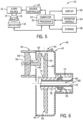
- FIG. 6 illustrates a cross-sectional view of an X-ray source 12 incorporating embodiments of the invention.
- X-ray source 12 is an X-ray tube 40 that includes an anode assembly 42 and a cathode assembly 44.
- the anode and cathode assemblies 42, 44 are supported within an insert or frame 46, which houses a target or anode 48, a bearing assembly 50, and a cathode 52.
- Frame 46 defines an area of y low pressure (e.g., a vacuum) compared to ambient, in which high voltages may be present.
- Frame 46 may be positioned within a casing (not shown) filled with a cooling medium, such as oil, that may also provide high voltage insulation. While the target and anode are described above as being a common component of X-ray tube 40, the target and anode may be separate components in alternative X-ray tube embodiments.
- an electron beam 54 is produced by cathode assembly 44.
- cathode 52 receives one or more electrical signals via a plurality of electrical leads 56.
- the electrical signals may include power and timing/control signals that cause cathode 52 to emit electron beam 54 at one or more energies and at one or more frequencies.
- the electrical signals may also at least partially control the potential between cathode 52 and anode 48.
- Cathode 52 includes an insulator 58 from which an arm 60 extends. Arm 60 encloses electrical leads 56, which extend into a cathode cup 62 mounted at the end of arm 60.
- cathode cup 62 includes focusing elements that focuses electrons emitted from a filament within cathode cup 62 to form electron beam 54.
- X-rays 64 are produced when high-speed electrons of electron beam 54 from cathode 52 are suddenly decelerated upon impacting a focal spot/target surface 66 formed on anode target 48.
- the high-speed electrons forming electron beam 54 are accelerated toward the anode target 48 via a potential difference therebetween of, for example, twenty (20) to one hundred and sixty (160) kV for medical diagnostic imaging , including sixty (60) kV or more in the case of CT applications.
- the X-rays 64 are emitted through a radiation emission window 68 formed in frame 46 that is positioned toward a detector array, such as detector 18 of FIG. 5 .
- the anode 48 On a target surface 66 of the body 100 that is positioned to face the cathode 54 within the path of the electron beam 52 remitted from the cathode 54, the anode 48 includes an emissive material track 104 disposed thereon.
- the emissive material track 104 is formed of a suitably emissive material, including but not limited to tungsten and/or rhodium.
- the difference between a first atomic number Z 1 of the material forming the emissive material track 104 and a second atomic number Z 2 of the relatively non-emissive material forming the body 100, or any other material 103 that is disposed on the surface 101 between the emissive material track 104 and the body 100 that is different than the material forming the body 100 should be at least 3% or more, or in another exemplary embodiment at least 7% or more, with the material forming the emissive material track 104 being higher in each case.
- the ratio between the first atomic number Z 1 of the material forming the emissive material track 104 and the second atomic number Z 2 of the relatively non-emissive material forming the body 100, or any other material 103 that is disposed on the surface 101 between the emissive material track 104 and the body 100 that is different than the material forming the body 100 can be at least greater than 6, and in another exemplary embodiment is at least greater than 12, again with the material forming the emissive material track 104 being higher in each case.
- the relatively non-emissive material forming the body 100 or material 103 is molybdenum, molybdenum alloy, or carbon, and the emissive material track 104 is formed from rhodium or tungsten alloy.
- the emissive material track 104 is positioned on the body 100 to cover and/or encompass the focal spot track 106 followed by the focal spot 107 to be struck by the electron beam 52 as it moves due to rotation of the anode 48 during the operation of the X-ray source 40.
- the emissive material track 104 can be attached to the body 100 in any suitable manner, such as by welding or brazing the emissive material track 104 to the body 100, or by depositing material forming the emissive material track 104 directly onto the body 100 in a suitable manner to form the emissive material track 104.
- the emissive material track 104 has a planar, generally circular ring shape to extend round the body 100 along the entire path of the focal spot track 106, i.e., the track or path of the focal spot/target surface 66 along the anode 48 as the anode is rotated during operation of the X-ray tube 12, during rotation of the anode 48, with an inner diameter ring 108 and an outer diameter ring 110.
- the first width or width W 1 of the emissive material track 104 between the inner ring 108 and the outer ring 110 is larger than the second width or width W 2 of the focal spot track 106, as defined by the length L 1 of the focal spot 107 defining the focal spot track 106, such that the entire focal spot track 106 can be encompassed within the width W 1 emissive material track 104.
- the width W 1 of the emissive material track 104 is significantly less than the radius R of the body 100 from the shaft 76 or sleeve 78 secured to the body 100 to a peripheral edge 115 of the body.
- the cathode 52 is operated to emit the electron beam 54 to strike the rotating anode 48 along focal spot track 106 to cause the emissive material track 104 to emit X-rays 120 within the focal spot track 106 overlapping the emissive material track 104.
- some of the electrons 122 within the electron beam 54 striking the emissive material track 104 can bounce or rebound off of the emissive material track 104, with some of these rebounding electrons 122 attracted back towards the anode 48.
- rebounding electrons 122 pass beyond the width W 1 of the emissive material track 104 and instead strike the body 100 formed of the suitably non-emissive substrate material to either side of the emissive material track 104.
- the focal spot track 106 is centered within the emissive material track 104.
- the emissive material track 104 extends outwardly to each side of the focal spot track 106 a distance of approximately one quarter of the width W 2 of the focal spot track 106.
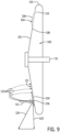
- an anode 148 includes a body 150 defining a peripheral surface 151 towards which an electron beam 54 is directed and formed of a suitable, or relatively non-emissive substrate material, similar or identical to the material forming body 100, and a shaft 152 operably connected to the body 150 and extending outwardly therefrom for attachment within a compatible X-ray source (not shown).
- the body 150 can be formed to have any of a multitude of suitable configurations, such as a body 150 that is conic in shape, with one or more angles between the cone of the body 150 and the axis defined by the shaft 152. In the exemplary illustrated embodiments of FIG.
- the body 150 is formed with a cylindrical shape, with the shaft 152 operably connected along a central axis of the body 150, and includes a pair of emissive material tracks 154,156 formed of materials similar to that of emissive material track 104 and disposed around the perimeter of the body 150. Further, the percentage difference and/or that rations for the first and second atomic numbers of the materials forming the body 150 and the emissive material tracks 154,156 can be the same as described previously with regard to body 100 and emissive material track 104.
- the emissive material tracks 154,156 can be spaced from one another, exposing one or more portions of the body 150, or any other material 153 that is disposed on the surface 151 between the emissive material tracks 154,156 and the body 150 that is different than the material forming the body 150, between the pair of emissive material tracks 154,156..
- the emissive material tracks 154,156 can be formed of the same type of emissive material, or can be formed from different types of emissive materials, such as chromium, aluminum, ytrrium, zirconium, magnesium, silicon, silver, titanium, molybdenum, rhodium and tungsten. Alternatively, as shown in FIG.
- the tracks 154,156 can be formed from a unitary layer 155 of emissive material having a blocking strip 157 of a lower X-ray emission capability material, i.e., low atomic number Z, disposed thereon, similar to body 150, thereby separating the unitary layer 155 into the emissive material tracks 154,156.
- the emissive material tracks 154,156 each have a different width, W 3 for track 154 and W 4 for track 156, such that the tracks 154 and 156 accommodate focal spot tracks 158,160 having different widths, i.e., W 5 for focal spot track 158 and W 6 for focal spot track 160 corresponding to the lengths L 2 and L 3 of the focal spots 107 defining each focal spot track 158,160, and that are each less than the width W 7 of the surface 151 of the body 150.
- the widths W 3 and W 4 of the emissive material tracks 154,156 each conform to the widths W 5 and W 6 for the focal spot tracks 158,160 according to the parameters of one or more of the embodiments discussed previously with regard to the anode 48 and the emissive material track 104 and focal spot track 106 disposed thereon.
- the single anode 148 can be employed for use in imaging procedures requiring different focal lengths, as the electron beam 54 can be directed onto the desired focal spot 107 and associated focal spot track(s) 158,160 and emissive material track(s) 154,156 to provide the improvements to the operation of the anode 148 provided by the emissive material tracks 154,156 as discussed previously.
- the anode 48 can be formed with a body 100 formed of an emissive material, i.e., with a high atomic number Z 1 , similar to that used for the emissive material tracks 104,154,156, such as that described previously.
- a blocking cover 162 formed of a low x-ray emission material as used with prior embodiments for the body 100 shown in FIGS.
- the cover 162 can be deposited in any suitable manner on the areas of the body 100 outside of the focal spot track(s) 106,158,160, with the material forming the cover 162 having suitable non-emission properties and a thickness of between 10 ⁇ m-100 ⁇ m, in one exemplary embodiment.
- the material forming the thermally conductive cover 164 such as a carbon material, e.g., carbon in diamond form, is capable of having the emissive material track(s) 104,154,156 deposited directly thereon over the area(s) of the body 100 and the cover 164 defining and/or aligned with the focal spot track(s) 106,158,160.
- a carbon material e.g., carbon in diamond form
- the thermally conductive cover 164 effectively prevents or limits the potential for rebounding electrons 122 to strike the body 100 outside of the emissive material track(s) 104,154,156 defining the focal spot track(s) 106,158,160, while also improving heat conductivity from the emissive material track(s) 104,154,156 defining the focal spot track(s) 106,158,160 to the remainder of the thermally conductive cover 164 and body 100 due to the improved thermal conductivity properties of the material forming the thermally conductive cover 164.
Landscapes
- X-Ray Techniques (AREA)
- Apparatus For Radiation Diagnosis (AREA)
Applications Claiming Priority (1)
| Application Number | Priority Date | Filing Date | Title |
|---|---|---|---|
| US18/243,283 US12512289B2 (en) | 2023-09-07 | 2023-09-07 | X-ray tube anode with optimized area focal spot track |
Publications (2)
| Publication Number | Publication Date |
|---|---|
| EP4531071A2 true EP4531071A2 (fr) | 2025-04-02 |
| EP4531071A3 EP4531071A3 (fr) | 2025-07-09 |
Family
ID=92459105
Family Applications (1)
| Application Number | Title | Priority Date | Filing Date |
|---|---|---|---|
| EP24195067.4A Pending EP4531071A3 (fr) | 2023-09-07 | 2024-08-16 | Anode de tube à rayons x avec piste de foyer à zone optimisée |
Country Status (3)
| Country | Link |
|---|---|
| US (1) | US12512289B2 (fr) |
| EP (1) | EP4531071A3 (fr) |
| CN (1) | CN119581297A (fr) |
Families Citing this family (2)
| Publication number | Priority date | Publication date | Assignee | Title |
|---|---|---|---|---|
| US20250006451A1 (en) * | 2018-02-01 | 2025-01-02 | Nova Measuring Instruments Inc. | Patterned x-ray emitting target |
| US12512289B2 (en) * | 2023-09-07 | 2025-12-30 | GE Precision Healthcare LLC | X-ray tube anode with optimized area focal spot track |
Family Cites Families (25)
| Publication number | Priority date | Publication date | Assignee | Title |
|---|---|---|---|---|
| US1953813A (en) * | 1930-11-29 | 1934-04-03 | Gen Electric | X-ray tube |
| DE1062827B (de) | 1957-10-12 | 1959-08-06 | Siemens Reiniger Werke Ag | Drehanoden-Roentgenroehre |
| DE1483302C3 (de) * | 1965-11-20 | 1975-10-16 | Siemens Ag, 1000 Berlin Und 8000 Muenchen | Verwendung einer Wolfram-Iridiumlegierung für die Anode von Röntgenröhren |
| AT300140B (de) | 1970-06-02 | 1972-07-10 | Metallwerk Plansee Ag & Co Kom | Drehanode für Röntgenröhren |
| US3821581A (en) * | 1971-08-02 | 1974-06-28 | Machlett Lab Inc | Targets for x ray tubes |
| US3795832A (en) * | 1972-02-28 | 1974-03-05 | Machlett Lab Inc | Target for x-ray tubes |
| US3973156A (en) * | 1974-01-23 | 1976-08-03 | U.S. Philips Corporation | Anode disc for an X-ray tube comprising a rotary anode |
| US4637042A (en) * | 1980-04-18 | 1987-01-13 | The Machlett Laboratories, Incorporated | X-ray tube target having electron pervious coating of heat absorbent material on X-ray emissive surface |
| US4573185A (en) * | 1984-06-27 | 1986-02-25 | General Electric Company | X-Ray tube with low off-focal spot radiation |
| JPS6276246A (ja) | 1985-09-30 | 1987-04-08 | Toshiba Corp | 回転陽極形x線管 |
| FR2617332B1 (fr) * | 1987-06-26 | 1995-06-23 | Thomson Cgr | Tube radiogene a faible rayonnement extra-focal |
| JP2001035428A (ja) * | 1999-07-22 | 2001-02-09 | Shimadzu Corp | X線発生装置 |
| US10483077B2 (en) * | 2003-04-25 | 2019-11-19 | Rapiscan Systems, Inc. | X-ray sources having reduced electron scattering |
| US7023950B1 (en) * | 2004-02-11 | 2006-04-04 | Martin Annis | Method and apparatus for determining the position of an x-ray cone beam produced by a scanning electron beam |
| DE102005062448A1 (de) | 2005-12-27 | 2007-07-05 | Siemens Ag | Verfahren und Vorrichtung zur Erzeugung eines Röntgenbilds |
| DE102005062447A1 (de) * | 2005-12-27 | 2007-07-05 | Siemens Ag | Vorrichtung zur Erzeugung eines Röntgenbilds |
| CN102124537A (zh) * | 2008-08-14 | 2011-07-13 | 皇家飞利浦电子股份有限公司 | 用于每个阳极盘段具有各自相对于旋转阳极的旋转轴线法平面的阳极倾斜角的旋转阳极型x射线管的多段阳极靶和包括具有这种多段阳极靶的旋转阳极的x射线管 |
| DE102009035439A1 (de) | 2009-07-31 | 2010-08-12 | Siemens Aktiengesellschaft | Röntgen-CT-System zur tomographischen Darstellung eines Untersuchungsobjektes, aufweisend eine Röntgenröhre zur Erzeugung von Röntgenstrahlung |
| JP2015506547A (ja) * | 2011-12-30 | 2015-03-02 | コーニンクレッカ フィリップス エヌ ヴェ | ろう付けx線管アノード |
| TWI629474B (zh) * | 2014-05-23 | 2018-07-11 | 財團法人工業技術研究院 | X光光源以及x光成像的方法 |
| WO2017204850A1 (fr) | 2016-05-27 | 2017-11-30 | Sigray, Inc. | Sources de rayons x divergents utilisant une accumulation linéaire |
| EP3496128A1 (fr) * | 2017-12-11 | 2019-06-12 | Koninklijke Philips N.V. | Anode rotative pour source de rayons x |
| JP7705852B2 (ja) * | 2019-10-24 | 2025-07-10 | ノヴァ メジャリング インスツルメンツ インコーポレイテッド | パターン化x線放出ターゲット |
| US11844641B2 (en) * | 2020-07-06 | 2023-12-19 | Michael Keith Fuller | Method and device for producing and using multiple origins of x-radiation |
| US12512289B2 (en) * | 2023-09-07 | 2025-12-30 | GE Precision Healthcare LLC | X-ray tube anode with optimized area focal spot track |
-
2023
- 2023-09-07 US US18/243,283 patent/US12512289B2/en active Active
-
2024
- 2024-08-16 EP EP24195067.4A patent/EP4531071A3/fr active Pending
- 2024-08-23 CN CN202411172095.5A patent/CN119581297A/zh active Pending
Also Published As
| Publication number | Publication date |
|---|---|
| CN119581297A (zh) | 2025-03-07 |
| US12512289B2 (en) | 2025-12-30 |
| US20250087439A1 (en) | 2025-03-13 |
| EP4531071A3 (fr) | 2025-07-09 |
Similar Documents
| Publication | Publication Date | Title |
|---|---|---|
| EP4531071A2 (fr) | Anode de tube à rayons x avec piste de foyer à zone optimisée | |
| JP4320415B2 (ja) | X線管用の薄型回転プレート・ターゲット | |
| US6215852B1 (en) | Thermal energy storage and transfer assembly | |
| US7869572B2 (en) | Apparatus for reducing kV-dependent artifacts in an imaging system and method of making same | |
| US8654928B2 (en) | X-ray tube target brazed emission layer | |
| US6125169A (en) | Target integral heat shield for x-ray tubes | |
| JP7717883B2 (ja) | X線陰極シールド | |
| JP7727038B2 (ja) | X線陰極シールド | |
| US7796737B2 (en) | Apparatus for reducing KV-dependent artifacts in an imaging system and method of making same | |
| US8009806B2 (en) | Apparatus and method of cooling a liquid metal bearing in an x-ray tube | |
| US7643614B2 (en) | Method and apparatus for increasing heat radiation from an x-ray tube target shaft | |
| EP1652208B1 (fr) | Tube a rayons x a anode profilee | |
| US7260181B2 (en) | Enhanced electron backscattering in x-ray tubes | |
| JPWO2012026381A1 (ja) | X線管装置及びx線ct装置 | |
| JP2003257347A (ja) | 回転陽極型x線管 | |
| US20090060139A1 (en) | Tungsten coated x-ray tube frame and anode assembly | |
| US9159523B2 (en) | Tungsten oxide coated X-ray tube frame and anode assembly | |
| US12520410B2 (en) | X-ray tube assembly and X-ray CT equipment | |
| EP4243050A2 (fr) | Elément de focalisation pour cathode à rayons x | |
| US7852987B2 (en) | X-ray tube having a rotating and linearly translating anode | |
| US8284899B2 (en) | X-ray tube having a focal spot proximate the tube end | |
| US7145988B2 (en) | Sealed electron beam source | |
| WO2012033027A1 (fr) | Dispositif à tube à rayons x, son procédé de fabrication et dispositif de diagnostic par images aux rayons x |
Legal Events
| Date | Code | Title | Description |
|---|---|---|---|
| PUAI | Public reference made under article 153(3) epc to a published international application that has entered the european phase |
Free format text: ORIGINAL CODE: 0009012 |
|
| STAA | Information on the status of an ep patent application or granted ep patent |
Free format text: STATUS: REQUEST FOR EXAMINATION WAS MADE |
|
| 17P | Request for examination filed |
Effective date: 20240816 |
|
| AK | Designated contracting states |
Kind code of ref document: A2 Designated state(s): AL AT BE BG CH CY CZ DE DK EE ES FI FR GB GR HR HU IE IS IT LI LT LU LV MC ME MK MT NL NO PL PT RO RS SE SI SK SM TR |
|
| PUAL | Search report despatched |
Free format text: ORIGINAL CODE: 0009013 |
|
| AK | Designated contracting states |
Kind code of ref document: A3 Designated state(s): AL AT BE BG CH CY CZ DE DK EE ES FI FR GB GR HR HU IE IS IT LI LT LU LV MC ME MK MT NL NO PL PT RO RS SE SI SK SM TR |
|
| RIC1 | Information provided on ipc code assigned before grant |
Ipc: H01J 35/10 20060101AFI20250603BHEP |