EP4531202A1 - Communication device - Google Patents
Communication device Download PDFInfo
- Publication number
- EP4531202A1 EP4531202A1 EP24199759.2A EP24199759A EP4531202A1 EP 4531202 A1 EP4531202 A1 EP 4531202A1 EP 24199759 A EP24199759 A EP 24199759A EP 4531202 A1 EP4531202 A1 EP 4531202A1
- Authority
- EP
- European Patent Office
- Prior art keywords
- waveguide
- antenna
- communication device
- stationary
- cavity
- Prior art date
- Legal status (The legal status is an assumption and is not a legal conclusion. Google has not performed a legal analysis and makes no representation as to the accuracy of the status listed.)
- Withdrawn
Links
Images
Classifications
-
- H—ELECTRICITY
- H01—ELECTRIC ELEMENTS
- H01P—WAVEGUIDES; RESONATORS, LINES, OR OTHER DEVICES OF THE WAVEGUIDE TYPE
- H01P3/00—Waveguides; Transmission lines of the waveguide type
- H01P3/12—Hollow waveguides
-
- H—ELECTRICITY
- H01—ELECTRIC ELEMENTS
- H01P—WAVEGUIDES; RESONATORS, LINES, OR OTHER DEVICES OF THE WAVEGUIDE TYPE
- H01P5/00—Coupling devices of the waveguide type
- H01P5/08—Coupling devices of the waveguide type for linking dissimilar lines or devices
- H01P5/10—Coupling devices of the waveguide type for linking dissimilar lines or devices for coupling balanced lines or devices with unbalanced lines or devices
- H01P5/103—Hollow-waveguide/coaxial-line transitions
-
- H—ELECTRICITY
- H01—ELECTRIC ELEMENTS
- H01P—WAVEGUIDES; RESONATORS, LINES, OR OTHER DEVICES OF THE WAVEGUIDE TYPE
- H01P5/00—Coupling devices of the waveguide type
- H01P5/12—Coupling devices having more than two ports
- H01P5/16—Conjugate devices, i.e. devices having at least one port decoupled from one other port
- H01P5/18—Conjugate devices, i.e. devices having at least one port decoupled from one other port consisting of two coupled guides, e.g. directional couplers
- H01P5/181—Conjugate devices, i.e. devices having at least one port decoupled from one other port consisting of two coupled guides, e.g. directional couplers the guides being hollow waveguides
- H01P5/182—Conjugate devices, i.e. devices having at least one port decoupled from one other port consisting of two coupled guides, e.g. directional couplers the guides being hollow waveguides the waveguides being arranged in parallel
Definitions
- the invention relates to a communication device according to the preamble of claim 1 and a conductor rail system according to the preamble of claim 11.
- the object of the invention is to provide an advantageous new solution for feeding and/or decoupling a microwave signal into or out of a slotted waveguide by means of a stationary antenna.
- the stationary antenna 11 can be arranged laterally centrally, i.e., aligned with the slot 5 of the first waveguide 2. Therefore, to maintain lateral symmetry, no second antenna is required.
- the central arrangement of the antenna 11 and the opening 13 in the longitudinal direction of the second waveguide 6 is preferred, but not mandatory.
- the propagation from the antenna 11 and the reception of electromagnetic waves by the antenna 11 are not direction-selective in this first embodiment, but they occur equally in both or from both directions along the first Waveguide 1.
- This embodiment is therefore primarily suitable for coupling and decoupling a signal at a point of a first waveguide 1 which is so far away from its ends that it is not necessary to prevent radiation from one end of the first waveguide 1, but rather radiation and reception in both or from both directions along the first waveguide 1 is desired.
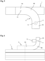
- a second embodiment of a communication device shows Fig. 5 in a plan view, ie in a view of the side of the first waveguide 1 opposite the slot 4.
- the second waveguide 6 in this embodiment does not have a straight shape, but rather it consists of two straight sections 6A and 6C, the longitudinal directions of which are perpendicular to one another, and of an arcuate section 6B which connects the two straight sections 6A and 6C.
- the first straight section 6A of the second waveguide 6 lies parallel to the first waveguide 1, as in the first embodiment, and the cavities of the two waveguides 1 and 6 are also connected to one another by an opening 13.
- the other straight section 6C of the second waveguide 6 protrudes in the plan view from Fig. 5 perpendicular to the longitudinal direction of the first waveguide 1.
- the antenna 11 and the connector 12 are arranged laterally away from the first waveguide 1.
- This provides the option of arranging the connector 12 and the cable to be connected to it optionally on the underside of the second waveguide 6, as shown in Fig. 5 is indicated by the dashed representation of these elements.
- This embodiment thus opens up an additional degree of design freedom and can be particularly advantageous if the connector 12 and the cable to be connected to it would have a disruptive effect in their arrangement on the top side of the second waveguide 6 as provided in the first embodiment.
- the other straight section 6C of the second waveguide 6 also projects here, as in the second embodiment, perpendicular to the longitudinal direction of the first waveguide 1, but in the side view of Fig. 6 upwards, i.e. compared to the second embodiment of Fig. 5 in a direction deviating by 90°.
- the antenna 11 and the connector 12 are arranged, whereby these elements can also be arranged differently than in Fig. 6 shown, can be arranged on that side of the section 6C of the second waveguide 6 which merges into the convex side of the arcuate section 6B, i.e. in Fig. 6 on the right side of section 6C.
- the third embodiment opens up the possibility of arranging the connector 12 parallel to the longitudinal axis of the waveguide 1, which can be advantageous when laying the cable to be connected to the connector 12 along the first waveguide 1, since a cable loop is avoided.
- the second waveguide 106 is also made of a conductive material, such as metal. It is attached to the first waveguide 102 such that a wall section 109 of the second waveguide 106 rests against the wall section 108 of the first waveguide 101 that is opposite its slot 104.
- the connection between the two waveguides 101 and 106 can be achieved, for example, by gluing, welding, a screw connection, or by a clamp surrounding the two waveguides 101 and 106 and pressing them together.
- the wall section 109 of the second waveguide 106 can also be formed by the wall section 108 of the first waveguide 101. In this case, to produce the second waveguide 106, only a U-shaped extruded profile with closed ends needs to be placed on the first waveguide 101 and connected to it.
- Two stationary antennas 111A and 111B extend into the cavity 107 inside the second waveguide 106 through a wall section 110 of the second waveguide 106, which is opposite the wall section 109 adjacent to the first waveguide 102. These antennas are each connected to a connector 112A and 112B on the outside of the wall section 110. A cable can be plugged into each of the connectors 112A and 112B to connect the antennas 111A and 111B to a stationary station.
- Both waveguides 101 and 106 each have two openings of equal size arranged laterally centrally in the cross-sectional view and at the same distance from each other in the longitudinal direction of the respective waveguide 101 or 106 and the second waveguide 106 is positioned on the first waveguide 101 in the longitudinal direction such that each of the two openings of the first waveguide 101 is aligned with an opening of the second waveguide 106 and together with this forms an opening 113A or 113B connecting the cavities 103 and 107 of the two waveguides 101 and 106 to one another.
- the distance d between the respective centers of the openings 113A and 113B in the longitudinal direction of the two waveguides 101 and 106 is one-quarter of the mean wavelength of the wavelength range for which the two waveguides 102 and 106 as well as the antennas 111A and 111B are designed.
- the arrangement of the openings 113A and 113B is symmetrical in the longitudinal direction to the two ends of the second waveguide 106.
- the antennas 111A and 111B are significantly further apart in the longitudinal direction of the second waveguide 106 than the two openings 113A and 113B. Their arrangement is preferably, but not necessarily, symmetrical to the two openings 113A and 113B in the longitudinal direction of the two waveguides 101 and 106.
- the propagation of waves radiated by the antennas 111A and 111B in the first waveguide 101 and the reception of electromagnetic waves by the antennas 111A and 111B from the first waveguide 101 are therefore direction-selective in this second embodiment with respect to the longitudinal direction of the first waveguide 101.
- This embodiment is therefore suitable for the simultaneous coupling and decoupling of various signals into and out of the first waveguide. from a waveguide 101 in or from opposite directions in the longitudinal direction of the waveguide 101.
- the fourth embodiment can be modified into a fifth embodiment, which is suitable for radiating a microwave signal into or receiving it from a waveguide 101 at one end thereof by omitting one of the two antennas 111A or 111B compared to the fourth embodiment, depending on which direction in the longitudinal direction of the first waveguide 101 is the desired direction of radiation and reception. It is understood that if one of the two antennas 111A or 111B is omitted, only effective radiation and effective reception in or from one of the two directions is possible, i.e., there is significant attenuation in the opposite direction of transmission and reception.
- the fifth embodiment is fundamentally also suitable for use at expansion joints between two successively arranged waveguides 101.
- only one antenna 111A or 111B is arranged on each of the two second waveguides 106, which is located closer to the expansion joint than the nearest of the two openings 113A and 113B.
- These two antennas are connected to each other by a flexible radio-frequency cable.
- the single antenna 11 of the first embodiment of the invention, as well as the two antennas 111A and 111B of the fourth embodiment, are connected to a transmitting and receiving device of a fixed station, which, for example, monitors and/or controls the movement of vehicles on the route along which a transmission path consisting of at least one first waveguide 1 or 101 runs.
- the microwave signal received by one of the two antennas 111A or 111B is significantly attenuated by destructive interference with the microwave signal received by the other antenna 111B or 111A. Which of the two received signals is significantly attenuated depends on the direction from which the microwave signal reached the coupling device 105 through the first waveguide 101.
- the receiving device of the fixed station can therefore be equipped with a comparison device which determines the direction of origin of a received microwave signal by comparing the powers received by the two antennas 111A and 111B.
- the second and third embodiments can also be combined with the fourth embodiment by, unlike in the Figures 5 and 6 not only at one end of the section 6A of the second waveguide 6 running parallel to the first waveguide 1, an arcuate section 6B is connected to this by a further straight section 6C, but at both ends of the first section 6A.
- two antennas 111A and 111B can be provided, namely one on each of the two sections 6C projecting perpendicularly from a first waveguide 101 in this case.
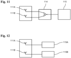
- Fig. 12 As shown in a block diagram, it is also possible in the fourth embodiment to provide two separate transmitting and receiving devices 115A and 115B for the fixed station, each of which is connected to only one of the two antennas 111A or 111B. By selecting different frequencies at which the two transmitting and receiving devices 115A and 115B operate, simultaneous communication via both antennas 111A and 111B in mutually opposite propagation directions in the first waveguide 101 is possible.
- the communication device described above can also be used as a component of a conductor rail system for the conductive transmission of electrical energy between a stationary mounted conductor rail and a current collector attached to an electrical load that can be moved longitudinally relative to the conductor rail.
- the conductor rail can be formed from the first waveguide 1, 101 and have conductor rail contacts running in the longitudinal direction, which are arranged in Figs. 3 and 4 or 9 and 10 are attached to the lower end and on both sides of the longitudinal slot 4, in particular inserted into the profile of the first waveguide 1, 101.
- directional waveguide couplers are known as such in microwave technology. However, they have so far been used exclusively for metrological purposes, namely to divert a small portion of the power of a microwave signal propagating in a waveguide in order to monitor the power radiated by a microwave transmitter and/or the reflection conditions of a waveguide transmission path.
- Antennas that, as components of a communications system, are intended to radiate microwave signals into a waveguide with the highest possible transmission power or to receive them from such a waveguide with the highest possible reception power always extend directly into the waveguide, which represents the transmission path intended for the microwave signals.
- the exemplary embodiments described above should not be understood as meaning that the features contained therein are all inseparable components of the invention. Rather, each individual feature of an exemplary embodiment can, on its own, i.e., even without its other features, make a significant contribution to the technical effect of the invention.
Landscapes
- Variable-Direction Aerials And Aerial Arrays (AREA)
- Waveguide Aerials (AREA)
Abstract
Bei einer Kommunikationsvorrichtung mit einem ersten Hohlwellenleiter (1; 101), der einen sich in seiner Längsrichtung erstreckenden Schlitz (4; 104) aufweist, und mit einer stationären Koppelvorrichtung (5; 105) zur Ein- und Auskopplung eines Mikrowellensignals in den bzw. aus dem ersten Hohlwellenleiter (1; 101) weist die Koppelvorrichtung (5; 105) einen zweiten Hohlwellenleiter (6; 106) auf, der an einer Seite ohne Schlitz des ersten Hohlwellenleiters (1; 101) mit diesem verbunden ist. Die Koppelvorrichtung (5; 105) weist mindestens eine stationäre Antenne (11; 111A, 111B) auf, die an dem zweiten Hohlwellenleiter (6; 106) in dessen Hohlraum (7; 107) hineinragend angeordnet ist, und sie weist mindestens eine die Hohlräume (3; 103, 7; 107) der beiden Hohlwellenleiter (1; 101, 6; 106) miteinander verbindende Öffnung (13; 113A, 113B) auf, die den Durchtritt von sich in einem der beiden Hohlwellenleiter (1; 101, 6; 106) ausbreitenden elektromagnetischen Wellen in den jeweils anderen Hohlwellenleiter (6; 106, 1; 101) ermöglicht.In a communication device with a first hollow waveguide (1; 101) which has a slot (4; 104) extending in its longitudinal direction, and with a stationary coupling device (5; 105) for coupling a microwave signal into and out of the first hollow waveguide (1; 101), the coupling device (5; 105) has a second hollow waveguide (6; 106) which is connected to the first hollow waveguide (1; 101) on a side without a slot. The coupling device (5; 105) has at least one stationary antenna (11; 111A, 111B) which is arranged on the second hollow waveguide (6; 106) so as to project into its cavity (7; 107), and it has at least one opening (13; 113A, 113B) which connects the cavities (3; 103, 7; 107) of the two hollow waveguides (1; 101, 6; 106) to one another and which enables the passage of electromagnetic waves propagating in one of the two hollow waveguides (1; 101, 6; 106) into the other hollow waveguide (6; 106, 1; 101).
Description
Die Erfindung betrifft eine Kommunikationsvorrichtung nach dem Oberbegriff des Anspruchs 1 sowie ein Schleifleitungssystem nach dem Oberbegriff des Anspruchs 11.The invention relates to a communication device according to the preamble of
Eine derartige Kommunikationsvorrichtung ist aus der
Ortsfeste Antennen werden außerdem auch an Dehnfugen, d.h. an kurzen Lücken zwischen in Längsrichtung aufeinanderfolgenden Hohlleitern benötigt. Solche Dehnfugen müssen bei langen Übertragungsstrecken, die aus mehreren aufeinanderfolgenden Hohlleitern bestehen, wegen der unvermeidlichen thermischen Längenänderung vorgesehen werden. In jedem von zwei durch eine Dehnfuge getrennten Hohlleitern ist nahe der Dehnfuge jeweils eine von zwei durch ein Koaxialkabel miteinander verbundenen ortsfesten Antennen angeordnet, um Signale über die Dehnfuge hinweg von einem Hohlleiter zum jeweils anderen zu übertragen.Fixed antennas are also required at expansion joints, i.e., at short gaps between longitudinally arranged waveguides. Such expansion joints must be provided for long transmission links consisting of several consecutive waveguides due to the unavoidable thermal expansion. In each of two waveguides separated by an expansion joint, one of two fixed antennas connected by a coaxial cable is located near the expansion joint to transmit signals from one waveguide to the other across the expansion joint.
Wenn sich die von einer ortsfesten Antenne in einen Hohlleiter abgestrahlten Wellen nur in einer gewünschten Richtung und nicht in beide Richtungen ausbreiten sollen, was insbesondere bei der Anordnung einer solchen Antenne nahe einem offenen Ende des Hohlleiters notwendig ist, muss sie mit einem Reflektor kombiniert werden, der die Ausbreitung in die unerwünschte Richtung, d.h. aus dem Hohlleiter hinaus, weitgehend verhindert. Hierzu wird üblicherweise ein sogenannter Kammreflektor eingesetzt, bei dem es sich um ein nach Art eines Kamms mit Schlitzen versehenes Blechstück oder um eine mit leitenden Streifen versehene Leiterplatte handelt, das sich innerhalb des Hohlleiters neben einer in diesen hineinragenden Antenne von dieser aus in die unerwünschte Ausbreitungsrichtung erstreckt. Die Verwendung eines solchen Kammreflektors ist in dem eingangs genannten Dokument ebenfalls beschrieben.If the waves radiated by a stationary antenna into a waveguide are to propagate only in one desired direction and not in both directions, which is particularly necessary when such an antenna is positioned near an open end of the waveguide, it must be combined with a reflector that largely prevents propagation in the undesired direction, i.e. out of the waveguide. For this purpose, a so-called comb reflector is usually used, which is a piece of sheet metal provided with slots like a comb, or a It is a circuit board provided with conductive strips that extends within the waveguide next to an antenna projecting into it, and from there into the undesired propagation direction. The use of such a comb reflector is also described in the document cited above.
Eine ortsfeste Antenne muss in einem geschlitzten Hohlleiter gegenüber dem Schlitz lateral versetzt angeordnet werden, damit sie von einer durch den Schlitz in den Hohlleiter ragenden Antenne eines Fahrzeugs passiert werden kann. Die üblicherweise lateral mittige Anordnung des Schlitzes erfordert somit eine lateral außermittige, also unsymmetrische Anordnung einer ortsfesten Antenne im Hohlraum des Hohlleiters, die für deren Abstrahlungs- und Empfangscharakteristik nicht optimal ist. Eine symmetrische ortsfeste Antennenkonfiguration kann durch die Verwendung von zwei Antennen erzielt werden, die symmetrisch zur Mitte des Querschnitts des Hohlleiters angeordnet sind, wie es die
Ausgehend von diesem Stand der Technik ist es die Aufgabe der Erfindung, für die Einspeisung und/oder Auskopplung eines Mikrowellensignals in bzw. aus einem geschlitzten Hohlleiter mittels einer ortsfesten Antenne eine vorteilhafte neue Lösung aufzuzeigen.Based on this prior art, the object of the invention is to provide an advantageous new solution for feeding and/or decoupling a microwave signal into or out of a slotted waveguide by means of a stationary antenna.
Die Erfindung löst diese Aufgabe durch eine Kommunikationsvorrichtung mit den Merkmalen des Anspruchs 1 sowie durch ein Schleifleitungssystem mit den Merkmalen des Anspruchs 11. Vorteilhafte Ausgestaltungen und zweckmäßige Weiterbildungen der Erfindung sind in den abhängigen Ansprüchen angegeben.The invention solves this problem by a communication device having the features of
Erfindungsgemäß ist bei einer Kommunikationsvorrichtung mit einem ersten Hohlleiter, der einen von einer elektrisch leitfähigen Wandung umgebenen ersten Hohlraum aufweist, wobei die Wandung an einer Seite einen sich in Längsrichtung des ersten Hohlleiters erstreckenden Schlitz aufweist, der eine Bewegung einer in den ersten Hohlraum hineinragenden Antenne entlang des Hohlleiters ermöglicht, und mit einer stationären Koppelvorrichtung zur Ein- und Auskopplung eines Mikrowellensignals in den bzw. aus dem ersten Hohlleiter vorgesehen, dass die Koppelvorrichtung einen zweiten Hohlleiter mit einem zweiten Hohlraum aufweist, der an einer Seite ohne Schlitz des ersten Hohlleiters mit diesem verbunden ist, dass die Koppelvorrichtung mindestens eine stationäre Antenne aufweist, die an dem zweiten Hohlleiter in den zweiten Hohlraum hineinragend angeordnet ist, und dass die Koppelvorrichtung mindestens eine die beiden Hohlräume miteinander verbindende Öffnung aufweist, die den Durchtritt von sich in einem der beiden Hohlleiter ausbreitenden elektromagnetischen Wellen in den jeweils anderen Hohlleiter ermöglicht.According to the invention, in a communication device with a first waveguide which has a first cavity surrounded by an electrically conductive wall, wherein the wall has on one side a slot extending in the longitudinal direction of the first waveguide, which slot allows a movement of an antenna projecting into the first cavity along the waveguide, and with a stationary Coupling device for coupling a microwave signal into and out of the first waveguide, the coupling device comprising a second waveguide with a second cavity which is connected to the first waveguide on one side without a slot, the coupling device comprising at least one stationary antenna which is arranged on the second waveguide projecting into the second cavity, and the coupling device comprising at least one opening which connects the two cavities to one another and which enables the passage of electromagnetic waves propagating in one of the two waveguides into the other waveguide.
Hierdurch muss bei der Anordnung einer stationären Antenne keine Rücksicht mehr darauf genommen werden, dass sie in dem ersten Hohlleiter von einer durch dessen Schlitz in diesen hineinragenden Antenne eines Fahrzeugs passiert werden kann, und die Montage oder Demontage der Antenne kann auch abseits des ersten Hohlleiters erfolgen. Der zweite Hohlleiter kann an dem ersten außenseitig befestigt werden und der unbedingt erforderliche Eingriff in den ersten Hohlleiter zur Ein- und Auskopplung von Mikrowellensignalen beschränkt sich auf die Herstellung mindestens einer Öffnung.This eliminates the need to consider the possibility of a vehicle antenna projecting through the slot in the first waveguide when arranging a stationary antenna. The antenna can also be mounted or dismounted away from the first waveguide. The second waveguide can be attached to the outside of the first waveguide, and the intervention in the first waveguide, which is absolutely necessary for coupling and decoupling microwave signals, is limited to creating at least one opening.
Die Länge des zweiten Hohlleiters ist wesentlich, vorzugsweise mindestens um den Faktor 10, geringer aus die Länge des ersten Hohlleiters, wodurch sich kompakte Abmessungen der Koppelvorrichtung ergeben. Für die Funktionsfähigkeit der Koppelvorrichtung genügt es nämlich, wenn die Länge des zweiten Hohlleiters in der Größenordnung der Wellenlänge der elektromagnetischen Wellen liegt, zu deren Ausbreitung der erste Hohlleiter ausgelegt ist. Eine größere Länge des zweiten Hohlleiters als nötig würde zwar die Funktionsfähigkeit der Koppelvorrichtung nicht in Frage stellen, doch ist unter den Gesichtspunkt des Materialaufwands eine möglichst geringe Länge des zweiten Hohlleiters, d.h. eine Länge in der Größenordnung besagter Wellenlänge zweckmäßig.The length of the second waveguide is significantly shorter than the length of the first waveguide, preferably at least by a factor of 10, resulting in compact dimensions for the coupling device. For the coupling device to function properly, it is sufficient if the length of the second waveguide is on the order of magnitude of the wavelength of the electromagnetic waves for which the first waveguide is designed. While a longer than necessary length of the second waveguide would not jeopardize the functionality of the coupling device, from the point of view of material expenditure, the shortest possible length of the second waveguide, i.e., a length on the order of magnitude of said wavelength, is expedient.
Vorzugsweise ist der zweite Hohlleiter an seinen beiden Längsenden geschlossen, wodurch ohne den Einsatz von Kammreflektoren eine unerwünschte Abstrahlung von Mikrowellenleistung in die Umgebung vermieden werden kann. Die Enden des ersten Hohlleiters können hingegen zumindest nicht beide geschlossen sein, weil dies die Einbringung einer fahrzeugseitigen Antenne an einem seiner Enden unmöglich machen würde.Preferably, the second waveguide is closed at both of its longitudinal ends, which prevents unwanted radiation of microwave power into the environment without the use of comb reflectors. However, the ends of the first waveguide cannot be closed at least both times, as this would make it impossible to install a vehicle-mounted antenna at one of its ends.
Bei einer vorteilhaften Ausführungsform hat der zweite Hohlleiter in seiner Längsrichtung einen parallel zu dem ersten Hohlleiter liegenden ersten geraden Abschnitt, der an mindestens einem seiner beiden Enden in einen bogenförmigen Abschnitt übergeht, der an seinem Ende in einen weiteren geraden Abschnitt übergeht, und eine stationäre Antenne ist an dem weiteren geraden Abschnitt angeordnet. Hierdurch eröffnen sich für die Anordnung und Ausrichtung des Steckverbinders, an den ein Kabel zur Verbindung der Antenne mit einer Sende- und/oder Empfangseinrichtung anschließbar ist, zusätzliche Freiheitsgrade, die eine kompakte Bauform der Koppelvorrichtung ermöglichen.In an advantageous embodiment, the second waveguide has a first straight section in its longitudinal direction, parallel to the first waveguide, which at least at one of its two ends transitions into an arcuate section, which at its end transitions into another straight section. A stationary antenna is arranged on the further straight section. This provides additional degrees of freedom for the arrangement and orientation of the connector, to which a cable for connecting the antenna to a transmitting and/or receiving device can be connected, thus enabling a compact design of the coupling device.
Bevorzugt ragt die mindestens eine stationäre Antenne in den zweiten Hohlraum von derjenigen Seite des zweiten Hohlleiters aus, welche der Öffnung gegenüberliegt, oder von derjenigen Seite des zweiten Hohlleiters aus, an welcher sich die Öffnung befindet, hinein. Diese Ausrichtung der Antenne ist für die Einkopplung eines Mikrowellensignals in den zweiten Hohlleiter und für dessen Überleitung in den ersten Hohlleiter vorteilhaft, da sich hierdurch eine übereinstimmende Polarisation mit dem von einer durch den Schlitz in den ersten Hohlraum ragenden Antenne eingekoppelten Mikrowellensignal ergibt.Preferably, the at least one stationary antenna extends into the second cavity from the side of the second waveguide opposite the opening, or from the side of the second waveguide where the opening is located. This orientation of the antenna is advantageous for coupling a microwave signal into the second waveguide and for transmitting it to the first waveguide, since it results in a matching polarization with the microwave signal coupled into the first cavity by an antenna extending through the slot.
Bei einer vorteilhaften Ausführungsform hat der zweite Hohlleiter eine gerade Form und die Längsrichtungen der beiden Hohlleiter liegen parallel zueinander, wodurch sich die Möglichkeit ergibt, dass sich die beiden Hohlleiter eine gemeinsame Wandung teilen. Der zweite Hohlleiter kann in diesem Fall in einfacher Weise durch die Befestigung eines im Querschnitt U-förmigen Strangprofils an einer Seite des ersten Hohlleiters hergestellt werden.In an advantageous embodiment, the second waveguide has a straight shape, and the longitudinal directions of the two waveguides are parallel to each other, which makes it possible for the two waveguides to share a common wall. In this case, the second waveguide can be easily manufactured by attaching an extruded profile with a U-shaped cross section to one side of the first waveguide.
Wenn keine Richtungsselektivität der Ein- und Auskopplung von Mikrowellensignalen bezüglich der Längsrichtung des ersten Hohlleiters erforderlich ist, genügt es, wenn nur eine stationäre Antenne und eine Öffnung vorgesehen sind.If no directional selectivity of the coupling and decoupling of microwave signals with respect to the longitudinal direction of the first waveguide is required, it is sufficient to provide only one stationary antenna and one opening.
Wenn eine Richtungsselektivität der Ein- und Auskopplung von Mikrowellensignalen bezüglich der Längsrichtung des ersten Hohlleiters erwünscht ist, so kann dies in einfacher Weise dadurch erreicht werden, dass zwei die beiden Hohlräume miteinander verbindende Öffnungen vorgesehen sind, deren Mittelpunkte in Längsrichtung der beiden Hohlleiter einen Abstand voneinander haben, der ein Viertel der Wellenlänge der elektromagnetischen Wellen beträgt, zu deren Ausbreitung der erste Hohlleiter ausgelegt ist, und dass eine Antenne zwischen einer der Öffnungen und dem dieser Öffnung nächstgelegenen Ende des zweiten Hohlleiters angeordnet ist. Durch destruktive Interferenz ergibt sich in diesem Fall eine starke Dämpfung von Mikrowellensignalen, welche bei ihrer Ausbreitung in dem ersten Hohlleiter zu den Öffnungen hin oder von diesem fort die Position der Antenne in Längsrichtung des ersten Hohlleiters passieren.If a directional selectivity of the coupling and decoupling of microwave signals with respect to the longitudinal direction of the first waveguide is desired, this can be achieved in a simple manner by providing two openings connecting the two cavities, the centers of which are spaced apart in the longitudinal direction of the two waveguides by a distance of one quarter of the wavelength of the electromagnetic waves for whose propagation the first waveguide is designed, and by The antenna is positioned between one of the openings and the end of the second waveguide closest to that opening. Destructive interference in this case results in a strong attenuation of microwave signals that pass the position of the antenna in the longitudinal direction of the first waveguide as they propagate in the first waveguide toward or away from the openings.
Vorzugsweise beträgt der Abstand der Antenne von dem ihr nächstgelegenen Ende des zweiten Hohlleiters ein Viertel der Wellenlänge der elektromagnetischen Wellen, zu deren Ausbreitung der erste Hohlleiter ausgelegt ist. Hierdurch ergibt sich eine minimale Dämpfung des von der Antenne abgestrahlten oder empfangenen Mikrowellensignals durch die Reflexion am nächstgelegenen Ende des zweiten Hohlleiters.Preferably, the distance between the antenna and the end of the second waveguide closest to it is one-quarter of the wavelength of the electromagnetic waves the first waveguide is designed to propagate. This results in minimal attenuation of the microwave signal emitted or received by the antenna due to reflection at the closest end of the second waveguide.
Vorzugsweise beträgt der Abstand der Antenne von der ihr nächstgelegenen Öffnung mindestens eine Wellenlänge der elektromagnetischen Wellen, zu deren Ausbreitung der erste Hohlleiter ausgelegt ist. Hierdurch wird eine wirksame Interferenz der durch verschiedene Öffnungen hindurchtretende Wellen auf ihrem Ausbreitungspfad gewährleistet.Preferably, the distance between the antenna and the opening closest to it is at least one wavelength of the electromagnetic waves the first waveguide is designed to propagate. This ensures effective interference between waves passing through different openings along their propagation path.
Eine bezüglich der Längsrichtung des ersten Hohlleiters bidirektionale Richtungsselektivität der Ein- und Auskopplung von Mikrowellensignalen in bzw. aus dem ersten Hohlleiter kann dadurch erreicht werden, dass zwischen jeder der zwei Öffnungen und dem der jeweiligen Öffnung nächstgelegenen Ende des zweiten Hohlleiters jeweils eine Antenne angeordnet ist. Bei dieser Anordnung erfahren sich innerhalb des ersten Hohlleiters ausbreitende Mikrowellensignale auf dem Weg zu einer der beiden Antennen eine starke Dämpfung durch destruktive Interferenz, wobei es von der Ausbreitungsrichtung abhängt, welche der beiden Antennen davon betroffen ist.Bidirectional directional selectivity of the coupling and decoupling of microwave signals into and out of the first waveguide with respect to the longitudinal direction of the first waveguide can be achieved by arranging an antenna between each of the two openings and the end of the second waveguide closest to the respective opening. With this arrangement, microwave signals propagating within the first waveguide experience significant attenuation due to destructive interference on their way to one of the two antennas. Which of the two antennas is affected depends on the direction of propagation.
Wenn eine mit den beiden stationären Antennen der Koppelvorrichtung verbindbare stationäre Sende- und Empfangseinrichtung eine Vergleichseinrichtung enthält, die dazu eingerichtet ist, anhand eines Vergleichs der Intensitäten der von den beiden stationären Antennen empfangenen Mikrowellensignale die Richtung zu ermitteln, aus welcher sich ein Mikrowellensignal in dem ersten Hohlleiter zu der Koppelvorrichtung hin ausgebreitet hat, so kann hieraus auf die Position des Senders entlang des ersten Hohlleiters bezüglich der Koppelvorrichtung geschlossen werden.If a stationary transmitting and receiving device that can be connected to the two stationary antennas of the coupling device contains a comparison device that is designed to determine the direction from which a microwave signal has propagated in the first waveguide to the coupling device based on a comparison of the intensities of the microwave signals received by the two stationary antennas, the position of the transmitter along the first waveguide with respect to the coupling device can be deduced from this.
Mittels eine Umschalteinrichtung, durch welche eine stationäre Sende- und Empfangseinrichtung wahlweise mit jeder einzelnen der beiden stationären Antennen verbindbar ist, kann ein Mikrowellensignal aufgrund der Richtungsselektivität der Koppelvorrichtung zur gezielten Ausbreitung in nur einer der beiden entgegengesetzten Richtungen in den ersten Hohlleiter eingekoppelt werden.By means of a switching device, by means of which a stationary transmitting and receiving device can be selectively connected to each of the two stationary antennas, a microwave signal can be coupled into the first waveguide for targeted propagation in only one of the two opposite directions due to the directional selectivity of the coupling device.
Mittels zweier Sende- und Empfangseinrichtungen, die zum Senden und Empfangen von Mikrowellensignalen auf voneinander verschiedenen Frequenzen eingerichtet sind, und von denen jede mit jeweils einer der beiden Antennen verbunden ist, kann eine ortsfeste Station gleichzeitig mit zwei verschiedenen Fahrzeugen, die sich an dem ersten Hohlleiter auf verschiedenen Seiten der Koppelvorrichtung befinden, kommunizieren.By means of two transmitting and receiving devices, which are designed to transmit and receive microwave signals at different frequencies, and each of which is connected to one of the two antennas, a fixed station can communicate simultaneously with two different vehicles located on the first waveguide on different sides of the coupling device.
Bevorzugt kann die oben und in den Ansprüchen beschriebene Kommunikationsvorrichtung bei einem Schleifleitungssystem zur konduktiven Übertragung elektrischer Energie zwischen einer ortsfest montierten länglichen Schleifleitung und einem an einem verfahrbaren elektrischen Verbraucher angebrachten Stromabnehmer verwendet werden. Bevorzugt kann die Schleifleitung hierzu in ihre Längsrichtung verlaufende Stromschienen aufweisen, welche bevorzugt in einem oder jeweils einem Hohlprofil mit einem in Längsrichtung verlaufenden Längsschlitz angeordnet sein können. Ein oder mehrere Schleifkontakte des Stromabnehmers können dann jeweils durch den bzw. die Längsschlitze in das Hohlprofil an die eine bzw. die Stromschienen bringbar sein. Weiter können die Stromschienen an dem ersten Hohlleiter, insbesondere an der den ersten Hohlraum umgebenden elektrisch leitfähigen Wandung direkt elektrisch leitend oder gegenüber dem ersten Hohlleiter elektrisch isoliert angeordnet sein.The communication device described above and in the claims can preferably be used in a conductor rail system for the conductive transmission of electrical energy between a stationary, elongated conductor rail and a current collector attached to a movable electrical load. For this purpose, the conductor rail can preferably have conductor rails running in its longitudinal direction, which can preferably be arranged in one or each of the hollow profiles with a longitudinal slot running in the longitudinal direction. One or more sliding contacts of the current collector can then each be brought to the one or more conductor rails through the longitudinal slot(s) in the hollow profile. Furthermore, the conductor rails can be arranged on the first waveguide, in particular on the electrically conductive wall surrounding the first cavity, in a directly electrically conductive manner, or electrically insulated from the first waveguide.
Weitere Besonderheiten und Vorteile der Erfindung ergeben sich aus der folgenden Beschreibung von bevorzugten Ausführungsbeispielen anhand der Zeichnungen. In diesen zeigen
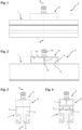
- Fig. 1
- eine Seitenansicht einer ersten Ausführungsform einer erfindungsgemäßen Kommunikationsvorrichtung;
- Fig. 2
- einen teilweisen Längsschnitt der Kommunikationsvorrichtung aus
Fig. 1 entlang der Linie A-A inFig. 3 ; - Fig. 3
- eine Vorderansicht der erfindungsgemäßen Kommunikationsvorrichtung aus
Fig. 1 ; - Fig. 4
- einen teilweisen Querschnitt der Kommunikationsvorrichtung aus
Fig. 1 entlang der Linie B-B inFig. 1 ; - Fig. 5
- eine Draufsicht auf eine zweite Ausführungsform einer erfindungsgemäßen Kommunikationsvorrichtung;
- Fig. 6
- eine Seitenansicht einer dritten Ausführungsform einer erfindungsgemäßen Kommunikationsvorrichtung;
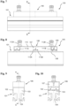
- Fig. 7
- eine Seitenansicht einer vierten Ausführungsform einer erfindungsgemäßen Kommunikationsvorrichtung;
- Fig. 8
- einen teilweisen Längsschnitt der Kommunikationsvorrichtung aus
Fig. 7 entlang der Linie A-A inFig. 9 ; - Fig. 9
- eine Vorderansicht der erfindungsgemäßen Kommunikationsvorrichtung aus
Fig. 7 ; - Fig. 10
- einen teilweisen Querschnitt der Kommunikationsvorrichtung aus
Fig. 7 entlang der Linie B-B inFig. 7 ; - Fig. 11
- ein Blockschaltbild zur vierten Ausführungsform der Erfindung;
- Fig. 12
- ein weiteres Blockschaltbild zur vierten Ausführungsform der Erfindung;
- Fig. 1
- a side view of a first embodiment of a communication device according to the invention;
- Fig. 2
- a partial longitudinal section of the communication device
Fig. 1 along line AA inFig. 3 ; - Fig. 3
- a front view of the communication device according to the invention
Fig. 1 ; - Fig. 4
- a partial cross-section of the communication device
Fig. 1 along line BB inFig. 1 ; - Fig. 5
- a plan view of a second embodiment of a communication device according to the invention;
- Fig. 6
- a side view of a third embodiment of a communication device according to the invention;
- Fig. 7
- a side view of a fourth embodiment of a communication device according to the invention;
- Fig. 8
- a partial longitudinal section of the communication device
Fig. 7 along line AA inFig. 9 ; - Fig. 9
- a front view of the communication device according to the invention
Fig. 7 ; - Fig. 10
- a partial cross-section of the communication device
Fig. 7 along line BB inFig. 7 ; - Fig. 11
- a block diagram of the fourth embodiment of the invention;
- Fig. 12
- another block diagram of the fourth embodiment of the invention;
Eine erste Ausführungsform einer erfindungsgemäßen Kommunikationsvorrichtung zeigen die
Zur Ein- und Auskopplung vom Mikrowellensignalen in bzw. aus dem ersten Hohlleiter 1 ist eine Koppelvorrichtung 5 vorgesehen. An der dem Schlitz 4 gegenüberliegenden Seite des ersten Hohlleiters 1 ist parallel zu diesem ein zweiter Hohlleiter 6 mit einem Hohlraum 7 angeordnet, dessen Querschnittsbreite, d.h. Querschnittsabmessung senkrecht zu dem Schlitz 4 etwa der Breite des Hohlraumes 3 des ersten Hohlleiters 1 entspricht. Die Länge des zweiten Hohlleiters 6 ist jedoch wesentlich geringer als diejenige des ersten Hohlleiters 1 und liegt in der Größenordnung der mittleren Wellenlänge der elektromagnetischen Wellen, zu deren Ausbreitung der erste Hohlleiter 1 ausgelegt ist. Der zweite Hohlleiter 6 weist keinen Schlitz auf und ist an seinen beiden Längsenden geschlossen.A
Auch der zweite Hohlleiter 6 besteht aus einem leitfähigen Material wie insbesondere Metall. Er ist an dem ersten Hohlleiter 1 so befestigt, dass an demjenigen Wandungsabschnitt 8 des ersten Hohlleiters 1, welcher dessen Schlitz 4 gegenüberliegt, ein Wandungsabschnitt 9 des zweiten Hohlleiters 6 anliegt. Die Verbindung der beiden Hohlleiter 1 und 6, die in den Figuren nicht dargestellt ist, kann beispielsweise durch Klebung, durch Schweißung, durch eine Schraubverbindung, oder durch eine die beiden Hohlleiter 1 und 6 umgebende und aneinander andrückende Klammer bewirkt werden. Der Wandungsabschnitt 9 des zweiten Hohlleiters 6 kann auch durch den Wandungsabschnitt 8 des ersten Hohlleiters 1 gebildet werden. In diesem Fall braucht zur Herstellung des zweiten Hohlleiters 6 nur ein im Querschnitt U-förmiges Strangprofil mit geschlossenen Enden auf den ersten Hohlleiters 1 aufgesetzt und mit diesem verbunden zu werden.The
In den Hohlraum 7 im Inneren des zweiten Hohlleiters 6 ragt durch einen Wandungsabschnitt 10 des zweiten Hohlleiters 6, welcher dem an dem ersten Hohlleiter 1 anliegenden Wandungsabschnitt 8 gegenüberliegt, eine stationäre Antenne 11 hinein, die mit einem Steckverbinder 12 an der Außenseite des Wandungsabschnitts 10 verbunden ist. An dem Steckverbinder 12 ist zur Verbindung der Antenne 11 mit einer ortsfesten Station ein Kabel ansteckbar.A
Beide Hohlleiter 1 und 6 weisen jeweils eine in der Querschnittsansicht lateral mittig angeordnete und gleich große Öffnung auf und der zweite Hohlleiter 6 ist an dem ersten Hohlleiter 1 in Längsrichtung so positioniert, dass die beiden Öffnungen miteinander fluchten und zusammen eine die Hohlräume 4 und 9 der beiden Hohlleiter 2 und 6 miteinander verbindende Öffnung 13 bilden. Die Größe der Öffnung 13 ist so gewählt, dass elektromagnetische Wellen in dem Wellenlängenbereich, für den die beiden Hohlleiter 1 und 6 sowie die Antenne 11 ausgelegt sind, durch sie hindurchtreten können, so dass von der Antenne 11 in den Hohlraum 9 des zweiten Hohlleiters 6 abgestrahlte Wellen durch die Öffnung 13 in den Hohlraum 4 des ersten Hohlleiters 1 gelangen und sich dort in dessen Längsrichtung ausbreiten können und von einer Antenne eines Fahrzeugs abgestrahlte und sich in dem ersten Hohlleiter 1 ausbreitende Wellen durch die Öffnung 13 in den Hohlraum 9 des zweiten Hohlleiters 6 gelangen und dort von der Antenne 11 empfangen werden können.Both
Die stationäre Antenne 11 kann aufgrund der Tatsache, dass sie nicht in den Hohlraum 4 des ersten Hohlleiters 1 hineinragt, lateral mittig, d.h. mit dem Schlitz 5 des ersten Hohlleiters 2 fluchtend angeordnet werden. Zur Wahrung einer lateralen Symmetrie muss also keine zweite Antenne vorgesehen werden. Die ebenfalls mittige Anordnung der Antenne 11 und der Öffnung 13 in Längsrichtung des zweiten Hohlleiters 6 ist bevorzugt, aber nicht obligatorisch.Due to the fact that it does not protrude into the
Die Ausbreitung von der Antenne 11 aus und der Empfang elektromagnetischer Wellen durch die Antenne 11 sind bei dieser ersten Ausführungsform nicht richtungsselektiv, sondern sie erfolgen gleichermaßen in beide bzw. aus beiden Richtungen längs des ersten Hohlleiters 1. Diese Ausführungsform eignet sich daher in erster Linie zur Ein- und Auskopplung eines Signals an einer Stelle eines ersten Hohlleiters 1, welche so weit von dessen Enden entfernt ist, dass eine Unterbindung der Abstrahlung aus einem Ende des ersten Hohlleiters 1 hinaus nicht notwendig ist, sondern vielmehr eine Abstrahlung sowie ein Empfang in beide bzw. aus beiden Richtungen längs des ersten Hohlleiters 1 erwünscht ist.The propagation from the
Eine zweite Ausführungsform einer erfindungsgemäßen Kommunikationsvorrichtung zeigt
Der andere gerade Abschnitt 6C des zweiten Hohlleiters 6 ragt in der Draufsicht von
Eine dritte Ausführungsform einer erfindungsgemäßen Kommunikationsvorrichtung zeigt
Der andere gerade Abschnitt 6C des zweiten Hohlleiters 6 ragt auch hier wie bei der zweiten Ausführungsform senkrecht zur Längsrichtung des ersten Hohlleiters 1 von diesem fort, jedoch in der Seitenansicht von
Eine vierte Ausführungsform einer erfindungsgemäßen Kommunikationsvorrichtung zeigen die
An der dem Schlitz 104 gegenüberliegenden Seite des ersten Hohlleiters 101 ist parallel zu dem ersten Hohlleiter 104 ein zweiter Hohlleiter 106 mit einem Hohlraum 107 angeordnet, dessen Querschnittsabmessungen annähernd denjenigen des Hohlraumes des ersten Hohlleiters 101 entsprechen. Die Länge des zweiten Hohlleiters 106 ist jedoch wesentlich geringer und liegt in der Größenordnung der Wellenlänge der elektromagnetischen Wellen, zu deren Ausbreitung der erste Hohlleiter 101 ausgelegt ist. Sie ist allerdings größer als die Länge des zweiten Hohlleiters 6 der ersten Ausführungsform. Bei dem in den
Auch der zweite Hohlleiter 106 besteht aus einem leitfähigen Material wie insbesondere Metall. Er ist an dem ersten Hohlleiter 102 so befestigt, dass ein Wandungsabschnitt 109 des zweiten Hohlleiters 106 an demjenigen Wandungsabschnitt 108 des ersten Hohlleiters 101, welcher dessen Schlitz 104 gegenüberliegt, anliegt. Die Verbindung der beiden Hohlleiter 101 und 106, die in den Figuren nicht dargestellt ist, kann beispielsweise durch Klebung, durch Schweißung, durch eine Schraubverbindung, oder durch eine die beiden Hohlleiter 101 und 106 umgebende und aneinander andrückende Klammer bewirkt werden. Der Wandungsabschnitt 109 des zweiten Hohlleiters 106 kann auch durch den Wandungsabschnitt 108 des ersten Hohlleiters 101 gebildet werden. In diesem Fall braucht zur Herstellung des zweiten Hohlleiters 106 nur ein im Querschnitt U-förmiges Strangprofil mit geschlossenen Enden auf den ersten Hohlleiters 101 aufgesetzt und mit diesem verbunden zu werden.The
In den Hohlraum 107 im Inneren des zweiten Hohlleiters 106 ragen durch einen Wandungsabschnitt 110 des zweiten Hohlleiters 106, welcher dem an dem ersten Hohlleiter 102 anliegenden Wandungsabschnitt 109 gegenüberliegt, zwei stationäre Antennen 111A und 111B hinein, die jeweils mit einem Steckverbinder 112A bzw. 112B an der Außenseite des Wandungsabschnitts 110 verbunden sind. An den Steckverbindern 112A und 112B ist zur Verbindung der Antennen 111A bzw. 111B mit einer ortsfesten Station jeweils ein Kabel ansteckbar.Two
Beide Hohlleiter 101 und 106 weisen jeweils zwei in der Querschnittsansicht lateral mittig angeordnete und gleich große Öffnungen im gleichen Abstand zueinander in Längsrichtung des jeweiligen Hohlleiters 101 bzw. 106 auf und der zweite Hohlleiter 106 ist an dem ersten Hohlleiter 101 in Längsrichtung so positioniert, dass jede der beiden Öffnungen des ersten Hohlleiters 101 mit jeweils einer Öffnung des zweiten Hohlleiters 106 fluchtet und zusammen mit dieser jeweils eine die Hohlräume 103 und 107 der beiden Hohlleiter 101 und 106 miteinander verbindende Öffnung 113A bzw. 113B bildet.Both
Die Größe der Öffnungen 113A und 113B ist so gewählt, dass elektromagnetische Wellen in dem Wellenlängenbereich, für den die beiden Hohlleiter 101 und 106 sowie die Antennen 111A und 111B ausgelegt sind, durch sie hindurchtreten können, so dass von den Antennen 111A und 111B abgestrahlte Wellen durch die Öffnungen 113A und 113B in den Hohlraum 103 des ersten Hohlleiters 101 gelangen und sich dort in dessen Längsrichtung ausbreiten können und von einer Antenne eines Fahrzeugs abgestrahlte und sich in dem Hohlleiter 101 ausbreitende Wellen durch die Öffnungen 113A und 113B in den Hohlraum 107 des zweiten Hohlleiters 106 gelangen und dort von den Antennen 111A und 111B empfangen werden können.The size of the
Der Abstand d der jeweiligen Mittelpunkte der Öffnungen 113A und 113B in Längsrichtung der beiden Hohlleiter 101 und 106 beträgt ein Viertel der mittleren Wellenlänge des Wellenlängenbereiches, für den die beiden Hohlleiter 102 und 106 sowie die Antennen 111A und 111B ausgelegt sind. Die Anordnung der Öffnungen 113A und 113B ist in Längsrichtung symmetrisch zu den beiden Enden des zweiten Hohlleiters 106. Die Antennen 111A und 111B sind in Längsrichtung des zweiten Hohlleiters 106 deutlich weiter voneinander entfernt als die beiden Öffnungen 113A und 113B. Ihre Anordnung ist in Längsrichtung der beiden Hohlleiter 101 und 106 vorzugsweise, aber nicht notwendigerweise symmetrisch zu den beiden Öffnungen 113A und 113B.The distance d between the respective centers of the
In dem in den
Infolge des Abstandes der Öffnungen 113A und 113B von einem Viertel der mittleren Wellenlänge, für welche die Hohlleiter 102 und 106 sowie die Antennen 111A und 111B ausgelegt sind, haben bei den Wellen, die sich in
Ein sich in dem ersten Hohlleiter 101 in
Der Effekt der destruktiven Interferenz aufgrund des Wegunterschiedes wirkt auch auf von den Antennen 111A und 111B abgestrahlten Signale. Ein von der Antenne 111A abgestrahltes Signal breitet sich in dem ersten Hohlleiter 101 von der Öffnung 113A aus nach links mit einer wesentlich geringeren Leistung aus als von den beiden Öffnungen 113A und 113B aus nach rechts. Aufgrund der Symmetrie der Anordnung gilt, dass ein von der Antenne 111B abgestrahltes Signal sich in dem ersten Hohlleiter 101 von der Öffnung 113B aus nach rechts mit einer wesentlich geringeren Leistung ausbreitet als von den beiden Öffnungen 113A und 113B aus nach links.The effect of destructive interference due to the path difference also affects signals radiated by
Die Ausbreitung von den Antennen 111A und 111B abgestrahlter Wellen in dem ersten Hohlleiter 101 und der Empfang elektromagnetischer Wellen durch die Antennen 111A und 111B aus dem ersten Hohlleiter 101 sind also bei dieser zweiten Ausführungsform bezüglich der Längsrichtung des ersten Hohlleiters 101 richtungsselektiv. Diese Ausführungsform eignet sich daher zur gleichzeitigen Ein- und Auskopplung verschiedener Signale in bzw. aus einem Hohlleiter 101 in bzw. aus entgegengesetzten Richtungen in der Längsrichtung des Hohlleiters 101.The propagation of waves radiated by the
Die stationären Antennen 111A und 111B können auch hier aufgrund der Tatsache, dass sie nicht in den Hohlraum 104 des ersten Hohlleiters 101 hineinragen, lateral mittig, d.h. mit dem Schlitz 103 des ersten Hohlleiters 101 fluchtend angeordnet werden. Zur Wahrung einer lateralen Symmetrie müssen also hier nur zwei und nicht vier Antennen vorgesehen werden.Here, too, the
Die vierte Ausführungsform kann zu einer fünften Ausführungsform modifiziert werden, welche dazu geeignet ist, ein Mikrowellensignal an einem Ende eines Hohlleiters 101 in diesen einzustrahlen oder aus diesem zu empfangen, indem gegenüber der vierten Ausführungsform eine der beiden Antennen 111A oder 111B weggelassen wird, je nachdem, welche Richtung in Längsrichtung des ersten Hohlleiters 101 die gewünschte Abstrahlungs- und Empfangsrichtung sein soll. Es versteht sich, dass bei einem Entfallen einer der beiden Antennen 111A oder 111B nur noch eine effektive Abstrahlung und ein effektiver Empfang in eine bzw. aus einer der beiden Richtungen möglich ist, d.h. dass in der entgegengesetzten Sende- und Empfangsrichtung eine starke Dämpfung erfolgt. Damit bei einer Anordnung am Ende eines Hohlleiters 101 die Abstrahlung und der Empfang in den Hohlleiter 101 bzw. aus diesem erfolgt, ist bei der dritten Ausführungsform die in diesem Fall einzige Antenne an dem zweiten Hohlleiter 106 näher bei dem Ende des ersten Hohlleiters 101 angeordnet als die Öffnungen 113A und 113B. Wenn beispielsweise in
Die fünfte Ausführungsform eignet sich grundsätzlich auch zur Verwendung an Dehnfugen zwischen zwei aufeinanderfolgend angeordneten Hohlleitern 101. In diesem Fall ist an jedem der beiden zweiten Hohlleiter 106 jeweils nur eine Antenne 111A bzw. 111B angeordnet, die sich jeweils näher an der Dehnfuge als die jeweils nächstgelegene der beiden Öffnungen 113A und 113B befindet. Diese beiden Antennen sind durch ein flexibles Hochfrequenzkabel miteinander verbunden. Hierdurch wird ein am Ende eines der ersten Hohlleiter 101 ankommendes Mikrowellensignal nach der Ausbreitung durch die Öffnungen 113 A und 113B und den mit ersten Hohlleiter 101 verbundenen zweiten Hohlleiter 106 durch die in diesen hineinragende Antenne empfangen, über das Hochfrequenzkabel zu der in den anderen zweiten Hohlleiter 106 hineinragende Antenne übertragen, durch diese in den anderen zweiten Hohlleiter 106 abgestrahlt und breitet sich dann durch die dortigen Öffnungen 113A und 113B in den anderen ersten Hohlleiter 101 aus. Die Symmetrie der Anordnung ermöglicht auf dem beschriebenen Übertragungsweg eine bidirektionale Übertragung von Signalen über die Dehnfuge hinweg.The fifth embodiment is fundamentally also suitable for use at expansion joints between two successively arranged
Die einzige Antenne 11 der ersten Ausführungsform der Erfindung sowie die beiden Antennen 111A und 111B vierten Ausführungsform sind mit einer Sende- und Empfangseinrichtung einer ortsfesten Station verbunden, welche die Bewegung von Fahrzeugen auf der Fahrstrecke, entlang derer eine aus mindestens einem ersten Hohlleiter 1 bzw. 101 bestehende Übertragungsstrecke verläuft, beispielsweise überwacht und/oder steuert. Wie vorausgehend erwähnt, wird bei der vierten Ausführungsform das von einer der beiden Antennen 111A oder 111B empfangene Mikrowellensignal durch destruktive Interferenz gegenüber dem von der jeweils anderen Antenne 111B bzw. 111A empfangenen Mikrowellensignal stark gedämpft. Welches der beiden Empfangssignale stark gedämpft wird, hängt von der Richtung ab, aus welches das Mikrowellensignal durch den ersten Hohlleiter 101 zu der Koppelvorrichtung 105 gelangt ist. Die Empfangseinrichtung der ortsfesten Station kann daher mit einer Vergleichseinrichtung ausgestattet sein, die anhand eines Vergleichs der von den beiden Antennen 111A und 111B empfangenen Leistungen die Herkunftsrichtung eines empfangenen Mikrowellensignals ermittelt.The
Die zweite und dritte Ausführungsform können auch jeweils mit der vierten Ausführungsform kombiniert werden, indem sich anders als in den
Wie
Wie
Bevorzugt kann die oben beschriebene Kommunikationsvorrichtung auch als Bestandteil eines Schleifleitungssystems zur konduktiven Übertragung elektrischer Energie zwischen einer ortsfest montierten Schleifleitung und einem an einem gegenüber der Schleifleitung u.a. in Längsrichtung verfahrbaren elektrischen Verbraucher angebrachten Stromabnehmer verwendet werden. Dabei kann die Schleifleitung aus dem ersten Hohlleiter 1, 101 gebildet sein und in Längsrichtung verlaufende Schleifleitungskontakte aufweisen, welche in
Es sei erwähnt, dass Hohlleiter-Koppler mit Richtwirkung als solche in der Mikrowellentechnik bekannt sind. Sie werden jedoch bisher ausschließlich zu messtechnischen Zwecken verwendet, nämlich dazu, einen kleinen Leistungsanteil eines sich in einem Hohlleiter ausbreitenden Mikrowellensignals abzuzweigen, um die von einem Mikrowellensender abgestrahlte Leistung und/oder die Reflexionsverhältnisse einer Hohlleiter-Übertragungsstrecke zu überwachen. Antennen, die als Bestandteile eines Kommunikationssystems Mikrowellensignale mit möglichst großer Sendeleistung in einen Hohlleiter abstrahlen oder mit möglichst großer Empfangsleistung aus einem solchen empfangen sollen, ragen nach dem Stand der Technik stets unmittelbar in den Hohlleiter, welcher die für die Mikrowellensignale vorgesehene Übertragungsstrecke darstellt, hinein. Die vorausgehend beschriebenen Ausführungsbeispiele sind nicht so zu verstehen, dass die in ihnen jeweils enthaltenen Merkmale allesamt voneinander untrennbare Bestandteile der Erfindung wären. Vielmehr kann jedes einzelne Merkmal eines Ausführungsbeispiels für sich allein, d.h. auch ohne dessen andere Merkmale einen wesentlichen Beitrag zur technischen Wirkung der Erfindung leisten.It should be noted that directional waveguide couplers are known as such in microwave technology. However, they have so far been used exclusively for metrological purposes, namely to divert a small portion of the power of a microwave signal propagating in a waveguide in order to monitor the power radiated by a microwave transmitter and/or the reflection conditions of a waveguide transmission path. Antennas that, as components of a communications system, are intended to radiate microwave signals into a waveguide with the highest possible transmission power or to receive them from such a waveguide with the highest possible reception power always extend directly into the waveguide, which represents the transmission path intended for the microwave signals. The exemplary embodiments described above should not be understood as meaning that the features contained therein are all inseparable components of the invention. Rather, each individual feature of an exemplary embodiment can, on its own, i.e., even without its other features, make a significant contribution to the technical effect of the invention.
- 1, 1011, 101
- Erster HohlleiterFirst waveguide
- 2, 1022, 102
- Wandungwall
- 3, 1033, 103
- Erster HohlraumFirst cavity
- 4, 1044, 104
- Schlitzslot
- 5, 1055, 105
- Koppelvorrichtungcoupling device
- 6, 1066, 106
- Zweiter HohlleiterSecond waveguide
- 6A, 6B, 6C6A, 6B, 6C
- Abschnitte des zweiten HohlleitersSections of the second waveguide
- 7, 1077, 107
- Zweiter HohlraumSecond cavity
- 8, 1088, 108
- Anliegender WandungsabschnittAdjacent wall section
- 9, 1099, 109
- Anliegender WandungsabschnittAdjacent wall section
- 10, 11010, 110
- Gegenüberliegender WandungsabschnittOpposite wall section
- 11, 111A, 111B11, 111A, 111B
- Antenneantenna
- 12, 112A, 112B12, 112A, 112B
- Steckverbinderconnectors
- 13, 113A, 113B13, 113A, 113B
- Öffnungopening
- 114114
- Umschalteinrichtungswitching device
- 115, 115A, 115B115, 115A, 115B
- Sende- und EmpfangseinrichtungTransmitting and receiving device
Claims (15)
Applications Claiming Priority (1)
| Application Number | Priority Date | Filing Date | Title |
|---|---|---|---|
| DE202023105653.9U DE202023105653U1 (en) | 2023-09-28 | 2023-09-28 | communication device |
Publications (1)
| Publication Number | Publication Date |
|---|---|
| EP4531202A1 true EP4531202A1 (en) | 2025-04-02 |
Family
ID=92762214
Family Applications (1)
| Application Number | Title | Priority Date | Filing Date |
|---|---|---|---|
| EP24199759.2A Withdrawn EP4531202A1 (en) | 2023-09-28 | 2024-09-11 | Communication device |
Country Status (2)
| Country | Link |
|---|---|
| EP (1) | EP4531202A1 (en) |
| DE (1) | DE202023105653U1 (en) |
Citations (7)
| Publication number | Priority date | Publication date | Assignee | Title |
|---|---|---|---|---|
| US2562281A (en) * | 1944-06-14 | 1951-07-31 | Bell Telephone Labor Inc | Directive pickup for transmission lines |
| EP0221401A1 (en) * | 1985-10-25 | 1987-05-13 | Siemens Aktiengesellschaft | Rotating data transmission device |
| US6002305A (en) * | 1997-09-25 | 1999-12-14 | Endgate Corporation | Transition between circuit transmission line and microwave waveguide |
| DE102009052871A1 (en) | 2009-09-08 | 2011-03-24 | Sew-Eurodrive Gmbh & Co. Kg | Device for contactlessly transmitting energy and/or data to rail vehicle, has slotted profile parts suspended, clamped or form-fitly connected with rail profile parts in direction that is oriented perpendicular to rail direction |
| DE102011108584A1 (en) | 2011-07-27 | 2013-01-31 | Sew-Eurodrive Gmbh & Co. Kg | Arrangement for data transmission between a first system part, in particular a stationary system part, and a mobile part which can be moved relative to the first system part |
| DE102017130960A1 (en) * | 2017-12-21 | 2019-06-27 | Paul Vahle Gmbh & Co. Kg | Profile body which forms a support profile and / or hollow waveguide and has at least one conductor rail profile |
| DE102018003066A1 (en) * | 2018-04-16 | 2019-10-17 | Sew-Eurodrive Gmbh & Co Kg | System with slot waveguide, receiving part and antenna part |
-
2023
- 2023-09-28 DE DE202023105653.9U patent/DE202023105653U1/en active Active
-
2024
- 2024-09-11 EP EP24199759.2A patent/EP4531202A1/en not_active Withdrawn
Patent Citations (7)
| Publication number | Priority date | Publication date | Assignee | Title |
|---|---|---|---|---|
| US2562281A (en) * | 1944-06-14 | 1951-07-31 | Bell Telephone Labor Inc | Directive pickup for transmission lines |
| EP0221401A1 (en) * | 1985-10-25 | 1987-05-13 | Siemens Aktiengesellschaft | Rotating data transmission device |
| US6002305A (en) * | 1997-09-25 | 1999-12-14 | Endgate Corporation | Transition between circuit transmission line and microwave waveguide |
| DE102009052871A1 (en) | 2009-09-08 | 2011-03-24 | Sew-Eurodrive Gmbh & Co. Kg | Device for contactlessly transmitting energy and/or data to rail vehicle, has slotted profile parts suspended, clamped or form-fitly connected with rail profile parts in direction that is oriented perpendicular to rail direction |
| DE102011108584A1 (en) | 2011-07-27 | 2013-01-31 | Sew-Eurodrive Gmbh & Co. Kg | Arrangement for data transmission between a first system part, in particular a stationary system part, and a mobile part which can be moved relative to the first system part |
| DE102017130960A1 (en) * | 2017-12-21 | 2019-06-27 | Paul Vahle Gmbh & Co. Kg | Profile body which forms a support profile and / or hollow waveguide and has at least one conductor rail profile |
| DE102018003066A1 (en) * | 2018-04-16 | 2019-10-17 | Sew-Eurodrive Gmbh & Co Kg | System with slot waveguide, receiving part and antenna part |
Also Published As
| Publication number | Publication date |
|---|---|
| DE202023105653U1 (en) | 2025-01-09 |
Similar Documents
| Publication | Publication Date | Title |
|---|---|---|
| DE2443166C3 (en) | System switch for separating two signals, each consisting of two double polarized frequency bands | |
| DE69826223T2 (en) | Microstrip line antenna and antenna containing device | |
| DE112013001764B4 (en) | Antenna field device with slotted waveguide | |
| DE2517383C3 (en) | System crossover for dual use of frequencies | |
| DE1027266B (en) | Serial coupler for microwaves with strip or ribbon lines | |
| EP2535978B1 (en) | Orthomode coupler for an antenna system | |
| DE102014112467B4 (en) | FOOD NETWORK FOR ANTENNA SYSTEMS | |
| DE102015114967A1 (en) | Distributor and planar antenna | |
| DE112018006815T5 (en) | Waveguide to microstrip line converter and antenna device | |
| EP2897213B1 (en) | Broadband signal splitting with sum signal absorption | |
| DE69121632T2 (en) | Polarization switch between a circular waveguide and a coaxial cable | |
| DE3689178T2 (en) | Double-comb duplex device with band-stop resonators. | |
| DE3020514A1 (en) | AERIAL FEEDING SYSTEM FOR A TRACKABLE AERIAL | |
| EP3861590B1 (en) | Communications system | |
| DE10143688B4 (en) | Directional coupler, antenna device and radar system | |
| DE2719283C2 (en) | Antenna feed system for double polarization | |
| EP4531202A1 (en) | Communication device | |
| EP0147693B1 (en) | Broadband polarisation filter | |
| EP0633621A1 (en) | Antenna-filter-combiner | |
| DE69713005T2 (en) | Balanced mixer | |
| DE102010014864B4 (en) | Waveguide connection for an antenna system and antenna system | |
| DE2708271A1 (en) | Polarisation division filter for satellite communication - has double branches with transverse electric and transverse magnetic mixing sections | |
| EP0280151B1 (en) | Microwave polarisation filter | |
| DE10328880B4 (en) | Mobile antenna of a base station | |
| DE102024111788A1 (en) | High-frequency component |
Legal Events
| Date | Code | Title | Description |
|---|---|---|---|
| PUAI | Public reference made under article 153(3) epc to a published international application that has entered the european phase |
Free format text: ORIGINAL CODE: 0009012 |
|
| STAA | Information on the status of an ep patent application or granted ep patent |
Free format text: STATUS: THE APPLICATION HAS BEEN PUBLISHED |
|
| AK | Designated contracting states |
Kind code of ref document: A1 Designated state(s): AL AT BE BG CH CY CZ DE DK EE ES FI FR GB GR HR HU IE IS IT LI LT LU LV MC ME MK MT NL NO PL PT RO RS SE SI SK SM TR |
|
| STAA | Information on the status of an ep patent application or granted ep patent |
Free format text: STATUS: THE APPLICATION HAS BEEN WITHDRAWN |
|
| 18W | Application withdrawn |
Effective date: 20250811 |