EP4531202A1 - Dispositif de communication - Google Patents
Dispositif de communication Download PDFInfo
- Publication number
- EP4531202A1 EP4531202A1 EP24199759.2A EP24199759A EP4531202A1 EP 4531202 A1 EP4531202 A1 EP 4531202A1 EP 24199759 A EP24199759 A EP 24199759A EP 4531202 A1 EP4531202 A1 EP 4531202A1
- Authority
- EP
- European Patent Office
- Prior art keywords
- waveguide
- antenna
- communication device
- stationary
- cavity
- Prior art date
- Legal status (The legal status is an assumption and is not a legal conclusion. Google has not performed a legal analysis and makes no representation as to the accuracy of the status listed.)
- Withdrawn
Links
Images


Classifications
-
- H—ELECTRICITY
- H01—ELECTRIC ELEMENTS
- H01P—WAVEGUIDES; RESONATORS, LINES, OR OTHER DEVICES OF THE WAVEGUIDE TYPE
- H01P3/00—Waveguides; Transmission lines of the waveguide type
- H01P3/12—Hollow waveguides
-
- H—ELECTRICITY
- H01—ELECTRIC ELEMENTS
- H01P—WAVEGUIDES; RESONATORS, LINES, OR OTHER DEVICES OF THE WAVEGUIDE TYPE
- H01P5/00—Coupling devices of the waveguide type
- H01P5/08—Coupling devices of the waveguide type for linking dissimilar lines or devices
- H01P5/10—Coupling devices of the waveguide type for linking dissimilar lines or devices for coupling balanced lines or devices with unbalanced lines or devices
- H01P5/103—Hollow-waveguide/coaxial-line transitions
-
- H—ELECTRICITY
- H01—ELECTRIC ELEMENTS
- H01P—WAVEGUIDES; RESONATORS, LINES, OR OTHER DEVICES OF THE WAVEGUIDE TYPE
- H01P5/00—Coupling devices of the waveguide type
- H01P5/12—Coupling devices having more than two ports
- H01P5/16—Conjugate devices, i.e. devices having at least one port decoupled from one other port
- H01P5/18—Conjugate devices, i.e. devices having at least one port decoupled from one other port consisting of two coupled guides, e.g. directional couplers
- H01P5/181—Conjugate devices, i.e. devices having at least one port decoupled from one other port consisting of two coupled guides, e.g. directional couplers the guides being hollow waveguides
- H01P5/182—Conjugate devices, i.e. devices having at least one port decoupled from one other port consisting of two coupled guides, e.g. directional couplers the guides being hollow waveguides the waveguides being arranged in parallel
Definitions
- the invention relates to a communication device according to the preamble of claim 1 and a conductor rail system according to the preamble of claim 11.
- the object of the invention is to provide an advantageous new solution for feeding and/or decoupling a microwave signal into or out of a slotted waveguide by means of a stationary antenna.
- the stationary antenna 11 can be arranged laterally centrally, i.e., aligned with the slot 5 of the first waveguide 2. Therefore, to maintain lateral symmetry, no second antenna is required.
- the central arrangement of the antenna 11 and the opening 13 in the longitudinal direction of the second waveguide 6 is preferred, but not mandatory.
- the propagation from the antenna 11 and the reception of electromagnetic waves by the antenna 11 are not direction-selective in this first embodiment, but they occur equally in both or from both directions along the first Waveguide 1.
- This embodiment is therefore primarily suitable for coupling and decoupling a signal at a point of a first waveguide 1 which is so far away from its ends that it is not necessary to prevent radiation from one end of the first waveguide 1, but rather radiation and reception in both or from both directions along the first waveguide 1 is desired.
- a second embodiment of a communication device shows Fig. 5 in a plan view, ie in a view of the side of the first waveguide 1 opposite the slot 4.
- the second waveguide 6 in this embodiment does not have a straight shape, but rather it consists of two straight sections 6A and 6C, the longitudinal directions of which are perpendicular to one another, and of an arcuate section 6B which connects the two straight sections 6A and 6C.
- the first straight section 6A of the second waveguide 6 lies parallel to the first waveguide 1, as in the first embodiment, and the cavities of the two waveguides 1 and 6 are also connected to one another by an opening 13.
- the other straight section 6C of the second waveguide 6 protrudes in the plan view from Fig. 5 perpendicular to the longitudinal direction of the first waveguide 1.
- the antenna 11 and the connector 12 are arranged laterally away from the first waveguide 1.
- This provides the option of arranging the connector 12 and the cable to be connected to it optionally on the underside of the second waveguide 6, as shown in Fig. 5 is indicated by the dashed representation of these elements.
- This embodiment thus opens up an additional degree of design freedom and can be particularly advantageous if the connector 12 and the cable to be connected to it would have a disruptive effect in their arrangement on the top side of the second waveguide 6 as provided in the first embodiment.
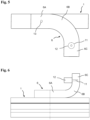
- the other straight section 6C of the second waveguide 6 also projects here, as in the second embodiment, perpendicular to the longitudinal direction of the first waveguide 1, but in the side view of Fig. 6 upwards, i.e. compared to the second embodiment of Fig. 5 in a direction deviating by 90°.
- the antenna 11 and the connector 12 are arranged, whereby these elements can also be arranged differently than in Fig. 6 shown, can be arranged on that side of the section 6C of the second waveguide 6 which merges into the convex side of the arcuate section 6B, i.e. in Fig. 6 on the right side of section 6C.
- the third embodiment opens up the possibility of arranging the connector 12 parallel to the longitudinal axis of the waveguide 1, which can be advantageous when laying the cable to be connected to the connector 12 along the first waveguide 1, since a cable loop is avoided.
- the second waveguide 106 is also made of a conductive material, such as metal. It is attached to the first waveguide 102 such that a wall section 109 of the second waveguide 106 rests against the wall section 108 of the first waveguide 101 that is opposite its slot 104.
- the connection between the two waveguides 101 and 106 can be achieved, for example, by gluing, welding, a screw connection, or by a clamp surrounding the two waveguides 101 and 106 and pressing them together.
- the wall section 109 of the second waveguide 106 can also be formed by the wall section 108 of the first waveguide 101. In this case, to produce the second waveguide 106, only a U-shaped extruded profile with closed ends needs to be placed on the first waveguide 101 and connected to it.
- Two stationary antennas 111A and 111B extend into the cavity 107 inside the second waveguide 106 through a wall section 110 of the second waveguide 106, which is opposite the wall section 109 adjacent to the first waveguide 102. These antennas are each connected to a connector 112A and 112B on the outside of the wall section 110. A cable can be plugged into each of the connectors 112A and 112B to connect the antennas 111A and 111B to a stationary station.
- Both waveguides 101 and 106 each have two openings of equal size arranged laterally centrally in the cross-sectional view and at the same distance from each other in the longitudinal direction of the respective waveguide 101 or 106 and the second waveguide 106 is positioned on the first waveguide 101 in the longitudinal direction such that each of the two openings of the first waveguide 101 is aligned with an opening of the second waveguide 106 and together with this forms an opening 113A or 113B connecting the cavities 103 and 107 of the two waveguides 101 and 106 to one another.
- the distance d between the respective centers of the openings 113A and 113B in the longitudinal direction of the two waveguides 101 and 106 is one-quarter of the mean wavelength of the wavelength range for which the two waveguides 102 and 106 as well as the antennas 111A and 111B are designed.
- the arrangement of the openings 113A and 113B is symmetrical in the longitudinal direction to the two ends of the second waveguide 106.
- the antennas 111A and 111B are significantly further apart in the longitudinal direction of the second waveguide 106 than the two openings 113A and 113B. Their arrangement is preferably, but not necessarily, symmetrical to the two openings 113A and 113B in the longitudinal direction of the two waveguides 101 and 106.
- the propagation of waves radiated by the antennas 111A and 111B in the first waveguide 101 and the reception of electromagnetic waves by the antennas 111A and 111B from the first waveguide 101 are therefore direction-selective in this second embodiment with respect to the longitudinal direction of the first waveguide 101.
- This embodiment is therefore suitable for the simultaneous coupling and decoupling of various signals into and out of the first waveguide. from a waveguide 101 in or from opposite directions in the longitudinal direction of the waveguide 101.
- the fourth embodiment can be modified into a fifth embodiment, which is suitable for radiating a microwave signal into or receiving it from a waveguide 101 at one end thereof by omitting one of the two antennas 111A or 111B compared to the fourth embodiment, depending on which direction in the longitudinal direction of the first waveguide 101 is the desired direction of radiation and reception. It is understood that if one of the two antennas 111A or 111B is omitted, only effective radiation and effective reception in or from one of the two directions is possible, i.e., there is significant attenuation in the opposite direction of transmission and reception.
- the fifth embodiment is fundamentally also suitable for use at expansion joints between two successively arranged waveguides 101.
- only one antenna 111A or 111B is arranged on each of the two second waveguides 106, which is located closer to the expansion joint than the nearest of the two openings 113A and 113B.
- These two antennas are connected to each other by a flexible radio-frequency cable.
- the single antenna 11 of the first embodiment of the invention, as well as the two antennas 111A and 111B of the fourth embodiment, are connected to a transmitting and receiving device of a fixed station, which, for example, monitors and/or controls the movement of vehicles on the route along which a transmission path consisting of at least one first waveguide 1 or 101 runs.
- the microwave signal received by one of the two antennas 111A or 111B is significantly attenuated by destructive interference with the microwave signal received by the other antenna 111B or 111A. Which of the two received signals is significantly attenuated depends on the direction from which the microwave signal reached the coupling device 105 through the first waveguide 101.
- the receiving device of the fixed station can therefore be equipped with a comparison device which determines the direction of origin of a received microwave signal by comparing the powers received by the two antennas 111A and 111B.
- the second and third embodiments can also be combined with the fourth embodiment by, unlike in the Figures 5 and 6 not only at one end of the section 6A of the second waveguide 6 running parallel to the first waveguide 1, an arcuate section 6B is connected to this by a further straight section 6C, but at both ends of the first section 6A.
- two antennas 111A and 111B can be provided, namely one on each of the two sections 6C projecting perpendicularly from a first waveguide 101 in this case.
- Fig. 12 As shown in a block diagram, it is also possible in the fourth embodiment to provide two separate transmitting and receiving devices 115A and 115B for the fixed station, each of which is connected to only one of the two antennas 111A or 111B. By selecting different frequencies at which the two transmitting and receiving devices 115A and 115B operate, simultaneous communication via both antennas 111A and 111B in mutually opposite propagation directions in the first waveguide 101 is possible.
- the communication device described above can also be used as a component of a conductor rail system for the conductive transmission of electrical energy between a stationary mounted conductor rail and a current collector attached to an electrical load that can be moved longitudinally relative to the conductor rail.
- the conductor rail can be formed from the first waveguide 1, 101 and have conductor rail contacts running in the longitudinal direction, which are arranged in Figs. 3 and 4 or 9 and 10 are attached to the lower end and on both sides of the longitudinal slot 4, in particular inserted into the profile of the first waveguide 1, 101.
- directional waveguide couplers are known as such in microwave technology. However, they have so far been used exclusively for metrological purposes, namely to divert a small portion of the power of a microwave signal propagating in a waveguide in order to monitor the power radiated by a microwave transmitter and/or the reflection conditions of a waveguide transmission path.
- Antennas that, as components of a communications system, are intended to radiate microwave signals into a waveguide with the highest possible transmission power or to receive them from such a waveguide with the highest possible reception power always extend directly into the waveguide, which represents the transmission path intended for the microwave signals.
- the exemplary embodiments described above should not be understood as meaning that the features contained therein are all inseparable components of the invention. Rather, each individual feature of an exemplary embodiment can, on its own, i.e., even without its other features, make a significant contribution to the technical effect of the invention.
Landscapes
- Variable-Direction Aerials And Aerial Arrays (AREA)
- Waveguide Aerials (AREA)
Applications Claiming Priority (1)
| Application Number | Priority Date | Filing Date | Title |
|---|---|---|---|
| DE202023105653.9U DE202023105653U1 (de) | 2023-09-28 | 2023-09-28 | Kommunikationsvorrichtung |
Publications (1)
| Publication Number | Publication Date |
|---|---|
| EP4531202A1 true EP4531202A1 (fr) | 2025-04-02 |
Family
ID=92762214
Family Applications (1)
| Application Number | Title | Priority Date | Filing Date |
|---|---|---|---|
| EP24199759.2A Withdrawn EP4531202A1 (fr) | 2023-09-28 | 2024-09-11 | Dispositif de communication |
Country Status (2)
| Country | Link |
|---|---|
| EP (1) | EP4531202A1 (fr) |
| DE (1) | DE202023105653U1 (fr) |
Citations (7)
| Publication number | Priority date | Publication date | Assignee | Title |
|---|---|---|---|---|
| US2562281A (en) * | 1944-06-14 | 1951-07-31 | Bell Telephone Labor Inc | Directive pickup for transmission lines |
| EP0221401A1 (fr) * | 1985-10-25 | 1987-05-13 | Siemens Aktiengesellschaft | Dispositif rotatif de transmission de données |
| US6002305A (en) * | 1997-09-25 | 1999-12-14 | Endgate Corporation | Transition between circuit transmission line and microwave waveguide |
| DE102009052871A1 (de) | 2009-09-08 | 2011-03-24 | Sew-Eurodrive Gmbh & Co. Kg | Vorrichtung zur Energie- und/oder Datenübertragung |
| DE102011108584A1 (de) | 2011-07-27 | 2013-01-31 | Sew-Eurodrive Gmbh & Co. Kg | Anordnung zur Datenübertragung zwischen einem ersten Anlagenteil, insbesondere stationärer Anlagenteil, und einem relativ zum ersten Anlagenteil verfahrbaren Mobilteil |
| DE102017130960A1 (de) * | 2017-12-21 | 2019-06-27 | Paul Vahle Gmbh & Co. Kg | Profilkörper, der ein Tragprofil und/oder Hohlwellenleiter bildet und mindestens ein Schleifleitungsprofil aufweist |
| DE102018003066A1 (de) * | 2018-04-16 | 2019-10-17 | Sew-Eurodrive Gmbh & Co Kg | System mit Schlitzhohlleiter, Aufnahmeteil und Antennenteil |
-
2023
- 2023-09-28 DE DE202023105653.9U patent/DE202023105653U1/de active Active
-
2024
- 2024-09-11 EP EP24199759.2A patent/EP4531202A1/fr not_active Withdrawn
Patent Citations (7)
| Publication number | Priority date | Publication date | Assignee | Title |
|---|---|---|---|---|
| US2562281A (en) * | 1944-06-14 | 1951-07-31 | Bell Telephone Labor Inc | Directive pickup for transmission lines |
| EP0221401A1 (fr) * | 1985-10-25 | 1987-05-13 | Siemens Aktiengesellschaft | Dispositif rotatif de transmission de données |
| US6002305A (en) * | 1997-09-25 | 1999-12-14 | Endgate Corporation | Transition between circuit transmission line and microwave waveguide |
| DE102009052871A1 (de) | 2009-09-08 | 2011-03-24 | Sew-Eurodrive Gmbh & Co. Kg | Vorrichtung zur Energie- und/oder Datenübertragung |
| DE102011108584A1 (de) | 2011-07-27 | 2013-01-31 | Sew-Eurodrive Gmbh & Co. Kg | Anordnung zur Datenübertragung zwischen einem ersten Anlagenteil, insbesondere stationärer Anlagenteil, und einem relativ zum ersten Anlagenteil verfahrbaren Mobilteil |
| DE102017130960A1 (de) * | 2017-12-21 | 2019-06-27 | Paul Vahle Gmbh & Co. Kg | Profilkörper, der ein Tragprofil und/oder Hohlwellenleiter bildet und mindestens ein Schleifleitungsprofil aufweist |
| DE102018003066A1 (de) * | 2018-04-16 | 2019-10-17 | Sew-Eurodrive Gmbh & Co Kg | System mit Schlitzhohlleiter, Aufnahmeteil und Antennenteil |
Also Published As
| Publication number | Publication date |
|---|---|
| DE202023105653U1 (de) | 2025-01-09 |
Similar Documents
| Publication | Publication Date | Title |
|---|---|---|
| DE2443166C3 (de) | Systemweiche zur Trennung zweier Signale, die aus je zwei doppelt polarisierten Frequenzbändern bestehen | |
| DE69826223T2 (de) | In Mikrostreifenleitungstechnik ausgeführte Antenne und diese enthaltende Vorrichtung | |
| DE112013001764B4 (de) | Antennenfeldvorrichtung mit geschlitztem Wellenleiter | |
| DE2517383C3 (de) | Systemweiche für Frequenzdoppelausnutzung | |
| DE1027266B (de) | Serien-Koppler fuer Mikrowellen mit Streifen- oder Bandleitung | |
| EP2535978B1 (fr) | Coupleur d'orthomodes pour un système d'antennes | |
| DE102014112467B4 (de) | Speisenetzwerk für antennensysteme | |
| DE102015114967A1 (de) | Verteiler und Planarantenne | |
| DE112018006815T5 (de) | Wellenleiter-Mikrostreifenleitungswandler und Antenneneinrichtung | |
| EP2897213B1 (fr) | Séparateur de signaux à larges bandes avec absorption du signal de la somme | |
| DE69121632T2 (de) | Polarisationsweiche zwischen einem zirkularen Wellenleiter und einem Koaxialkabel | |
| DE3689178T2 (de) | Doppelkammduplexgerät mit Bandsperrenresonatoren. | |
| DE3020514A1 (de) | Antennenspeisesystem fuer eine nachfuehrbare antenne | |
| EP3861590B1 (fr) | Système de communication | |
| DE10143688B4 (de) | Richtungskoppler, Antennenvorrichtung und Radarsystem | |
| DE2719283C2 (de) | Antennenspeisesystem für Doppelpolarisation | |
| EP4531202A1 (fr) | Dispositif de communication | |
| EP0147693B1 (fr) | Filtre de polarisation à large bande | |
| EP0633621A1 (fr) | Filtre-combineur pour antenne | |
| DE69713005T2 (de) | Gegentaktmischer | |
| DE102010014864B4 (de) | Hohlleiterverbindung für ein Antennensystem und Antennensystem | |
| DE2708271A1 (de) | Polarisationsweiche | |
| EP0280151B1 (fr) | Filtre de polarisation aux micro-ondes | |
| DE10328880B4 (de) | Mobilfunkantenne einer Basisstation | |
| DE102024111788A1 (de) | Hochfrequenzbauteil |
Legal Events
| Date | Code | Title | Description |
|---|---|---|---|
| PUAI | Public reference made under article 153(3) epc to a published international application that has entered the european phase |
Free format text: ORIGINAL CODE: 0009012 |
|
| STAA | Information on the status of an ep patent application or granted ep patent |
Free format text: STATUS: THE APPLICATION HAS BEEN PUBLISHED |
|
| AK | Designated contracting states |
Kind code of ref document: A1 Designated state(s): AL AT BE BG CH CY CZ DE DK EE ES FI FR GB GR HR HU IE IS IT LI LT LU LV MC ME MK MT NL NO PL PT RO RS SE SI SK SM TR |
|
| STAA | Information on the status of an ep patent application or granted ep patent |
Free format text: STATUS: THE APPLICATION HAS BEEN WITHDRAWN |
|
| 18W | Application withdrawn |
Effective date: 20250811 |