EP4534036A2 - Polyaxiale schraube mit mehreren merkmalen - Google Patents
Polyaxiale schraube mit mehreren merkmalen Download PDFInfo
- Publication number
- EP4534036A2 EP4534036A2 EP25159408.1A EP25159408A EP4534036A2 EP 4534036 A2 EP4534036 A2 EP 4534036A2 EP 25159408 A EP25159408 A EP 25159408A EP 4534036 A2 EP4534036 A2 EP 4534036A2
- Authority
- EP
- European Patent Office
- Prior art keywords
- receiver member
- assembly
- bone anchor
- distal
- proximal
- Prior art date
- Legal status (The legal status is an assumption and is not a legal conclusion. Google has not performed a legal analysis and makes no representation as to the accuracy of the status listed.)
- Pending
Links
Images

















Classifications
-
- A—HUMAN NECESSITIES
- A61—MEDICAL OR VETERINARY SCIENCE; HYGIENE
- A61B—DIAGNOSIS; SURGERY; IDENTIFICATION
- A61B17/00—Surgical instruments, devices or methods
- A61B17/56—Surgical instruments or methods for treatment of bones or joints; Devices specially adapted therefor
- A61B17/58—Surgical instruments or methods for treatment of bones or joints; Devices specially adapted therefor for osteosynthesis, e.g. bone plates, screws or setting implements
- A61B17/68—Internal fixation devices, including fasteners and spinal fixators, even if a part thereof projects from the skin
- A61B17/70—Spinal positioners or stabilisers, e.g. stabilisers comprising fluid filler in an implant
- A61B17/7001—Screws or hooks combined with longitudinal elements which do not contact vertebrae
- A61B17/7032—Screws or hooks with U-shaped head or back through which longitudinal rods pass
- A61B17/7034—Screws or hooks with U-shaped head or back through which longitudinal rods pass characterised by a lateral opening
-
- A—HUMAN NECESSITIES
- A61—MEDICAL OR VETERINARY SCIENCE; HYGIENE
- A61B—DIAGNOSIS; SURGERY; IDENTIFICATION
- A61B17/00—Surgical instruments, devices or methods
- A61B17/56—Surgical instruments or methods for treatment of bones or joints; Devices specially adapted therefor
- A61B17/58—Surgical instruments or methods for treatment of bones or joints; Devices specially adapted therefor for osteosynthesis, e.g. bone plates, screws or setting implements
- A61B17/68—Internal fixation devices, including fasteners and spinal fixators, even if a part thereof projects from the skin
- A61B17/70—Spinal positioners or stabilisers, e.g. stabilisers comprising fluid filler in an implant
- A61B17/7001—Screws or hooks combined with longitudinal elements which do not contact vertebrae
- A61B17/7032—Screws or hooks with U-shaped head or back through which longitudinal rods pass
-
- A—HUMAN NECESSITIES
- A61—MEDICAL OR VETERINARY SCIENCE; HYGIENE
- A61B—DIAGNOSIS; SURGERY; IDENTIFICATION
- A61B17/00—Surgical instruments, devices or methods
- A61B17/56—Surgical instruments or methods for treatment of bones or joints; Devices specially adapted therefor
- A61B17/58—Surgical instruments or methods for treatment of bones or joints; Devices specially adapted therefor for osteosynthesis, e.g. bone plates, screws or setting implements
- A61B17/68—Internal fixation devices, including fasteners and spinal fixators, even if a part thereof projects from the skin
- A61B17/70—Spinal positioners or stabilisers, e.g. stabilisers comprising fluid filler in an implant
- A61B17/7001—Screws or hooks combined with longitudinal elements which do not contact vertebrae
- A61B17/7035—Screws or hooks, wherein a rod-clamping part and a bone-anchoring part can pivot relative to each other
- A61B17/7037—Screws or hooks, wherein a rod-clamping part and a bone-anchoring part can pivot relative to each other wherein pivoting is blocked when the rod is clamped
-
- A—HUMAN NECESSITIES
- A61—MEDICAL OR VETERINARY SCIENCE; HYGIENE
- A61B—DIAGNOSIS; SURGERY; IDENTIFICATION
- A61B17/00—Surgical instruments, devices or methods
- A61B17/56—Surgical instruments or methods for treatment of bones or joints; Devices specially adapted therefor
- A61B17/58—Surgical instruments or methods for treatment of bones or joints; Devices specially adapted therefor for osteosynthesis, e.g. bone plates, screws or setting implements
- A61B17/68—Internal fixation devices, including fasteners and spinal fixators, even if a part thereof projects from the skin
- A61B17/70—Spinal positioners or stabilisers, e.g. stabilisers comprising fluid filler in an implant
- A61B17/7001—Screws or hooks combined with longitudinal elements which do not contact vertebrae
- A61B17/7035—Screws or hooks, wherein a rod-clamping part and a bone-anchoring part can pivot relative to each other
- A61B17/7038—Screws or hooks, wherein a rod-clamping part and a bone-anchoring part can pivot relative to each other to a different extent in different directions, e.g. within one plane only
-
- A—HUMAN NECESSITIES
- A61—MEDICAL OR VETERINARY SCIENCE; HYGIENE
- A61B—DIAGNOSIS; SURGERY; IDENTIFICATION
- A61B17/00—Surgical instruments, devices or methods
- A61B17/56—Surgical instruments or methods for treatment of bones or joints; Devices specially adapted therefor
- A61B17/58—Surgical instruments or methods for treatment of bones or joints; Devices specially adapted therefor for osteosynthesis, e.g. bone plates, screws or setting implements
- A61B17/68—Internal fixation devices, including fasteners and spinal fixators, even if a part thereof projects from the skin
- A61B17/84—Fasteners therefor or fasteners being internal fixation devices
- A61B17/86—Pins or screws or threaded wires; nuts therefor
- A61B17/8605—Heads, i.e. proximal ends projecting from bone
- A61B17/861—Heads, i.e. proximal ends projecting from bone specially shaped for gripping driver
- A61B17/862—Heads, i.e. proximal ends projecting from bone specially shaped for gripping driver at the periphery of the screw head
-
- A—HUMAN NECESSITIES
- A61—MEDICAL OR VETERINARY SCIENCE; HYGIENE
- A61B—DIAGNOSIS; SURGERY; IDENTIFICATION
- A61B17/00—Surgical instruments, devices or methods
- A61B17/56—Surgical instruments or methods for treatment of bones or joints; Devices specially adapted therefor
- A61B17/58—Surgical instruments or methods for treatment of bones or joints; Devices specially adapted therefor for osteosynthesis, e.g. bone plates, screws or setting implements
- A61B17/68—Internal fixation devices, including fasteners and spinal fixators, even if a part thereof projects from the skin
- A61B17/84—Fasteners therefor or fasteners being internal fixation devices
- A61B17/86—Pins or screws or threaded wires; nuts therefor
- A61B17/864—Pins or screws or threaded wires; nuts therefor hollow, e.g. with socket or cannulated
-
- A—HUMAN NECESSITIES
- A61—MEDICAL OR VETERINARY SCIENCE; HYGIENE
- A61B—DIAGNOSIS; SURGERY; IDENTIFICATION
- A61B17/00—Surgical instruments, devices or methods
- A61B17/56—Surgical instruments or methods for treatment of bones or joints; Devices specially adapted therefor
- A61B17/58—Surgical instruments or methods for treatment of bones or joints; Devices specially adapted therefor for osteosynthesis, e.g. bone plates, screws or setting implements
- A61B17/68—Internal fixation devices, including fasteners and spinal fixators, even if a part thereof projects from the skin
- A61B17/84—Fasteners therefor or fasteners being internal fixation devices
- A61B17/86—Pins or screws or threaded wires; nuts therefor
- A61B17/8685—Pins or screws or threaded wires; nuts therefor comprising multiple separate parts
-
- A—HUMAN NECESSITIES
- A61—MEDICAL OR VETERINARY SCIENCE; HYGIENE
- A61B—DIAGNOSIS; SURGERY; IDENTIFICATION
- A61B17/00—Surgical instruments, devices or methods
- A61B17/56—Surgical instruments or methods for treatment of bones or joints; Devices specially adapted therefor
- A61B17/58—Surgical instruments or methods for treatment of bones or joints; Devices specially adapted therefor for osteosynthesis, e.g. bone plates, screws or setting implements
- A61B17/68—Internal fixation devices, including fasteners and spinal fixators, even if a part thereof projects from the skin
- A61B17/70—Spinal positioners or stabilisers, e.g. stabilisers comprising fluid filler in an implant
- A61B17/7001—Screws or hooks combined with longitudinal elements which do not contact vertebrae
- A61B17/7035—Screws or hooks, wherein a rod-clamping part and a bone-anchoring part can pivot relative to each other
-
- A—HUMAN NECESSITIES
- A61—MEDICAL OR VETERINARY SCIENCE; HYGIENE
- A61B—DIAGNOSIS; SURGERY; IDENTIFICATION
- A61B90/00—Instruments, implements or accessories specially adapted for surgery or diagnosis and not covered by any of the groups A61B1/00 - A61B50/00, e.g. for luxation treatment or for protecting wound edges
- A61B90/03—Automatic limiting or abutting means, e.g. for safety
- A61B2090/037—Automatic limiting or abutting means, e.g. for safety with a frangible part, e.g. by reduced diameter
Definitions
- This disclosure relates generally to improved polyaxial bone anchor assemblies, which can include a plurality of features, e.g., for optimized or improved engagement with surgical instruments, surgical instrumentation, and/or bone, applicable for use in at least thoracolumbar spinal applications.
- Bone anchor assemblies can be used in orthopedic surgery to fix bone during healing, fusion, or other processes.
- bone anchor assemblies can be used to secure a rod or other spinal fixation element to one or more vertebrae to rigidly or dynamically stabilize the spine.
- Bone anchor assemblies typically include a bone screw with a threaded shank that is adapted to be threaded into a vertebra, and a rod-receiving element, usually in the form of a U-shaped slot formed in the head.
- the shank and rod-receiving assembly can be provided as a monoaxial screw, whereby the rod-receiving element is fixed with respect to the shank, or a polyaxial screw, whereby the rod-receiving element has free angular movement with respect to the shank.
- the shank portion of each screw is threaded into a vertebra, and once properly positioned, a fixation rod is seated into the rod-receiving element of each screw. The rod is then locked in place by tightening a set-screw, plug, or similar type of fastening mechanism into the rod-receiving element.
- prior bone anchor assemblies there are a large variety of anchors suited for specific uses and this can make it difficult for a user to select the proper anchor, and for suppliers to manufacture and maintain inventories. Further, with prior anchors there are many ways in which use can be challenging, such as when implanting an anchor, when coupling instrumentation to an anchor, when reducing a spinal fixation element toward an anchor, etc.
- a bone anchor assembly in one aspect, includes a bone anchor having a proximal head portion and a distal threaded bone-engaging portion.
- the bone anchor further includes a receiver member having a proximal end defined by a pair of spaced apart arms forming a U-shaped recess therebetween, a distal end having a polyaxial seat formed therein for polyaxially seating the head portion of the bone anchor, a groove formed in an outer surface of each of the spaced apart arms at a proximal end thereof, a first recess formed in the outer surface of each arm with at least a portion of the first recess intersecting the groove, and a second recess formed in an outer surface of the receiver member at a position distal to the first recesses.
- the first recesses and the second recesses are configured to couple to a surgical instrument.
- first recess in each arm can extend proximally beyond the groove.
- each of the second recesses can be longitudinally aligned with one of the first recesses.
- the first recesses can be configured to pivotably couple to a surgical instrument.
- the pair of second recesses can be configured to pivotably couple to a surgical instrument.
- the U-shaped recess can be configured to receive a spinal fixation element of various sizes.
- each spaced apart arm can have a laterally-facing recessed portion formed on opposite lateral edges of the arm, each of the lateral-facing recessed portions facing away from a central proximal-distal axis of the receiver member, wherein the lateral-facing recessed portions can be configured to engage with a surgical instrument such that the U-shaped recess remains unobstructed.
- each of the lateral-facing recessed portions can extend distally from the proximal end of the spaced apart arms.
- each lateral-facing recessed portion can have a concave distal surface.
- each lateral-facing recessed portion can have a first planar surface, a second planar surface substantially perpendicular to the first planar surface, and a curved surface therebetween.
- each spaced apart arm can have a laterally-facing recessed portion formed on opposite lateral edges of the arm, each of the lateral-facing recessed portions facing away from a central proximal-distal axis of the receiver member, wherein the lateral-facing recessed portions are configured to engage with a surgical instrument such that the U-shaped recess remains unobstructed.
- Each of the lateral-facing recessed portions can extend distally from the proximal end of the spaced apart arms.
- Each lateral-facing recessed portion can have a concave distal surface.
- Each lateral-facing recessed portion can have a first planar surface, a second planar surface substantially perpendicular to the first planar surface, and a curved surface therebetween.
- the assembly can include a drag ring disposed within the receiver member, the drag ring configured to exert a friction force on the head portion of the bone anchor.
- the assembly can include a compression member disposed within the receiver member, wherein a proximal portion of the compression member includes opposing planar surfaces that are angularly offset from one another forming a seat for receiving a spinal fixation element.
- Material displaced in the formation of the second recesses can be configured to restrict movement of the compression member relative to the receiver member. The displaced material can be received within corresponding recesses formed in the compression member.
- the assembly can include a pair of reduction tabs extending proximally from the pair of spaced apart arms.
- the assembly can include a fixation element with external square threads configured to be received between the spaced apart arms of the receiver member.
- the bone anchor can include a bore extending proximally from a distal tip of the bone engaging portion.
- the bore can extend through an entire length of the bone anchor.
- the bore can be a blind bore.
- the distal bone-engaging portion can include external threads that extend distally along the bone-engaging portion to a distal tip thereof.
- a bone anchor assembly in another aspect, includes a bone anchor having a proximal head portion and a distal threaded bone-engaging portion.
- the assembly further includes a receiver member having a proximal end defined by a pair of spaced apart arms forming a U-shaped recess configured to receive a spinal fixation element therebetween and a distal end having a polyaxial seat formed therein for polyaxially seating the head portion of the bone anchor.
- proximal ends of the spaced apart arms lie along a common circular circumferential path.
- each spaced apart arm can have a laterally-facing recessed portion formed on opposite lateral edges of the arm, each of the lateral-facing recessed portions facing away from a central proximal-distal axis of the receiver member, wherein the lateral-facing recessed portions are configured to engage with a surgical instrument such that the U-shaped recess remains unobstructed.
- Each of the lateral-facing recessed portions can extend distally from the proximal end of the spaced apart arms.
- Each lateral-facing recessed portion can have a concave distal surface.
- Each lateral-facing recessed portion can have a first planar surface, a second planar surface substantially perpendicular to the first planar surface, and a curved surface therebetween.
- the proximal ends of the spaced apart arms can lie along a common circular circumferential path.
- the compression member can be locked against removal from an interior of the receiver member.
- a bone anchor assembly in another aspect, includes a bone anchor having a proximal portion and a distal threaded bone-engaging portion, as well as a locking sphere configured to couple to the proximal portion of the bone anchor.
- the assembly further includes a receiver member having a proximal end defined by a pair of spaced apart arms forming a U-shaped recess therebetween, and a distal end having a polyaxial seat formed therein for polyaxially seating the locking sphere, as well as a drag ring disposed within the receiver member and configured to exert a friction force on the locking sphere, and a compression member disposed within the receiver member.
- a distal facing surface of the receiver member is obliquely angled relative to a central proximal-distal axis of the receiver member to provide a greater degree of angulation of the bone anchor relative to the receiver member in a first direction relative to a second, opposite direction.
- the receiver member can include a groove formed in an outer surface of each of the spaced apart arms at a proximal end thereof. Further, the receiver member can include a first recess formed in the outer surface of each arm with at least a portion of the first recess intersecting the groove, and a second recess formed in an outer surface of the receiver member at a position distal to the first recesses. Moreover, the first and second recesses can be configured to couple to a surgical instrument. In some embodiments, At least a portion of the first recess in each arm extends proximally beyond the groove. The second recess can be longitudinally aligned with one of the first recesses. The first recesses can be configured to pivotably couple to a surgical instrument. The second recess can be configured to pivotably couple to a surgical instrument as well.
- the U-shaped recess can be configured to receive a spinal fixation element of various sizes.
- each spaced apart arm can have a laterally-facing recessed portion formed on opposite lateral edges of the arm, each of the lateral-facing recessed portions facing away from the central proximal-distal axis of the receiver member, wherein the lateral-facing recessed portions are configured to engage with a surgical instrument such that the U-shaped recess remains unobstructed.
- Each of the lateral-facing recessed portions can extend distally from the proximal end of the spaced apart arms.
- Each lateral-facing recessed portion can have a concave distal surface.
- Each lateral-facing recessed portion can have a first planar surface, a second planar surface substantially perpendicular to the first planar surface, and a curved surface therebetween.
- the proximal ends of the spaced apart arms can lie along a common circular circumferential path.
- opposing laterally-facing sides of the receiver member can taper inward towards the proximal end of the receiver member.
- a first pair of opposed sides of the receiver member can have a first taper with respect to a first plane that contains a proximal-distal axis of the receiver member.
- a second pair of opposed sides of the receiver member can have a second taper with respect to a second plane that contains the proximal-distal axis and is offset from the first plane.
- the first plane can be perpendicular to the second plane.
- a proximal portion of the compression member can include opposing planar surfaces that are angularly offset from one another forming a seat for receiving a spinal fixation element.
- Material displaced in the formation of the second recess can be configured to restrict movement of the compression member relative to the receiver member. The displaced material can be received within a corresponding recess formed in the compression member.
- the assembly can include a pair of reduction tabs extending proximally from the pair of spaced apart arms.
- the assembly can include a fixation element with external square threads configured to be received between the spaced apart arms of the receiver member.
- the bone anchor can include a bore extending proximally from a distal tip of the bone engaging portion.
- the bore can extend through an entire length of the bone anchor.
- the bone anchor can include at least one outlet formed in a lateral surface thereof that intersects with the bore.
- the bore can be a blind bore.
- the distal bone-engaging portion can include external threads that extend distally along the bone-engaging portion to a distal tip thereof.
- the compression member can be configured to exert a force on the locking sphere upon distal advancement of the compression member relative to the receiver member.
- the bone anchor can include threads of a first pitch formed along a first bone-engaging portion thereof and threads of a second pitch formed along a second bone-engaging portion that is proximal of the first bone engaging portion.
- the first pitch can be greater than the second pitch.
- the bone anchor can include threads formed on a first, distal portion thereof and a second portion without threads that is disposed between the first portion and the proximal portion of the bone anchor.
- a length of the second portion without threads can be at least about 30% of a length of the first portion having threads formed thereon.
- the length of the second portion can also be between about 30% and about 90% of the length of the first portion.
- like-numbered components of the embodiments can generally have similar features. Still further, sizes and shapes of the devices, and the components thereof, can depend at least on the anatomy of the subject in which the devices will be used, the size and shape of objects with which the devices will be used, and the methods and procedures in which the devices will be used.
- the bone anchor assemblies disclosed herein, and methods related to the same, provide for a single bone anchor assembly that can be utilized across a range of spinal surgical procedures, reduce manufacturing burden and cost, and provide for greater flexibility during a surgical procedure.
- the bone anchor assemblies disclosed herein include an implantable shank and a receiver member having two spaced apart arms which form a U-shaped seat to receive a rod, among other components.
- the bone anchor assemblies disclosed herein also provide a number of features to enhance capability and usability. These include, for example, features to facilitate better implantation of the shank, better coupling of instrumentation to the anchor, better performance in reducing a spinal fixation element, such as a rod, into the receiver member seat, and others.
- the receiver member 102 can receive spinal fixation elements of multiple sizes.
- spinal rods having a diameter of about 5.5 mm or a diameter of about 6.0 mm can be received within the rod-receiving recess 119.
- a proximal portion of the spaced apart arms 112, 114 of the receiver member 102 can include a threaded inner surface 410 that can engage with a set screw or other locking element received therebetween to lock a spinal rod within the receiver member 102.
- the inner threaded portion 410 can have square threads e.g., to engage with counterpart external square threads of a set screw (see FIG. 14 ).
- Bone anchor assemblies 100, 500 of the present disclosure can include a receiver member 102, 504 having a taper in one or more directions.
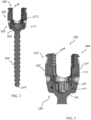
- FIG. 6 is a partially transparent view of the bone anchor assembly 100 of FIG. 1 that shows, among other things, a taper 602 of the outer surface of the receiver member 102 in a first direction. More particularly, a first pair of opposed sides 604, 606, shown in FIG. 6 as exterior walls of the spaced-apart arms 112, 114, can have a first taper with respect to a first plane that contains a proximal-distal axis A1 of the receiver member 102 (i.e., the plane of the page of FIG. 6 ). Alternatively, FIG.
- 60 shows an embodiment of a receiver member 5702 in which a first pair of opposed sides 6004, 6006, do not have a taper with respect to the first plane that contains a proximal-distal axis A1 of the receiver member. That is, the opposed sides 6004, 6006 of exterior walls of the spaced-apart arms 5712, 5714 have a substantially straight cylindrical shape.
- FIG. 7 is a partially transparent side view of the bone anchor assembly 100 of FIG. 1 in an orientation that is 90 degrees offset from the orientation shown in FIG. 6 .
- FIG. 7 illustrates, among other things, a taper 702 of the outer surface of the receiver member 102 in a second direction. More particularly, a second pair of opposed sides 704, 706, shown in FIG. 7 as exterior walls of the receiver member 120 that are 90 degrees offset from the first pair of opposed sides 604, 606, can have a second taper with respect to a second plane (i.e., the plane of the page of FIG. 7 ).
- the second plane contains the proximal-distal axis A1 of the receiver member and is offset from the first plane described above.
- the surfaces 704, 706, can be planar surfaces angled toward one another to create a second taper. As noted above, in some embodiments only one of these tapers may be utilized. For example, in the embodiment shown in FIGS. 57-62 , cylindrical surfaces 6004, 6006 do not taper while planar surfaces 7004, 7006 include a similar taper as surfaces 704, 706 in FIGS. 7 and 9 .
- the bone anchor assembly 100 can include a drag ring 204 disposed within a recess or groove 1702 (see FIG. 17 ) formed in a distal portion 120 of the receiver member 102.
- the drag ring 204 can create a friction fit between an interior surface 204' of the drag ring 204 and an exterior surface of the shank head 302, such that the receiver member 102 of the bone anchor assembly 100 can provisionally maintain a position relative to the bone shank 104 prior to a full locking of the bone anchor assembly 100, e.g., with a set screw or other locking element.
- the drag ring 204 can be disposed within the distal portion 120 of the receiver member 102 prior to insertion of the shank head 302.
- the distal end 120 of the receiver member 102 can include a polyaxial seat 608 for polyaxially seating the head 302 of the bone shank 104.
- This polyaxial connection can allow full range of motion of the bone shank 104 relative to the receiver member 102.
- a spherical recess in the distal end 120 of the receiver member 102 can receive a spherical portion of the shank head 302.
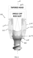
- FIGS. 10-12 illustrate one embodiment of a compression cap 202 of the present disclosure.
- FIG. 10 is a perspective view of one embodiment of a compression cap 202
- FIG. 11 is a front view of the compression cap 202 of FIG. 10
- FIG. 12 is a cross-sectional view of the compression cap 202 as shown in FIG. 11 .
- the outer surface of the compression cap 202 can include depressions or recesses 304 that can receive material from the receiver member 102 that is displaced during a swage that can form the second rocker feature 406.
- a proximal portion of the compression cap can form a seat for receiving a spinal rod.
- two planar surfaces 1002, 1004 of the compression cap can be angularly offset from one another to form a substantially "V" shaped groove that can seat a spinal rod of varying diameters. This is in comparison to conventional compression caps that often include a curved proximal surface with a radius matching a single spinal rod diameter.
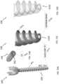
- FIGS. 13A-13D illustrate various aspects of one embodiment of a bone shank 104 of the present disclosure.
- FIG. 13A shows the bone anchor assembly 100 of FIG. 1 .
- FIG. 13B shows a top perspective view of the bone shank 104 in isolation.
- FIG. 13C shows an enlarged view of a distal end of the bone-engaging portion 108 of the bone shank 104.
- FIG. 13D shows a partially transparent enlarged view of the distal end of the bone-engaging portion 108 of the bone shank 104.
- External threads 1302 can extend along the bone-engaging portion 108 of the shank 104.
- Various thread forms can be utilized for shanks of the present disclosure, including solid dual lead, solid cortical fix, cannulated dual lead, cannulated cortical fix, and cannulated cortical fix fenestrated threads.
- the bone shank 104 can have a quick-start tip 1304, with threads that extend distally to a distal tip 3410 of the bone engaging portion 1310.
- the threads 1302 can extend to the contact surface between the bone shank 104 and the bone (not shown), which can provide immediate purchase of the thread into bone.
- a rounded tip is often used distal to the threads, which can require driving the screw into the bone axially some distance before threads can grip the bone.
- a recess 1306 can be centered and formed in the distal tip 1310 of the bone shank 104.
- This recess 1306, which can be referred to as a centering recess, can be used to support the distal bone-engaging portion 108 of the shank 104 in a centered manner during the manufacturing process.
- the centering recess can be a blind bore that extends proximally from the distal tip 1310 of the bone-engaging portion 108 (e.g., as shown in the partially transparent view of FIG. 13D ).
- the centering recess can be a full cannulated recess that extends from the proximal end to the distal end of the bone shank 104.
- a recess can allow, for example, for introduction of the shank 104 over a guidewire, delivery of cement or other flowable material through the shank 104 into bone, etc.
- a drive feature 1308 can be formed in the proximal head 302 of the bone shank 104 to allow a driver to control rotation of the anchor during implantation, etc. Any of a variety of drive feature designs can be utilized, including square drive, hex drive, lobed drives, etc.
- the illustrated embodiment includes a T27 drive feature.
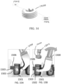
- FIG. 14 illustrates one embodiment of a set screw 1400 of the present disclosure.
- the set screw 1400 and proximal portion of the receiver member 102 inner surface 206 can each have complementary square threads 1402 (or other thread forms) formed thereon.
- the set screw 1400 can have a drive feature 1404 formed therein, such as the above-noted T27 drive feature 1404.
- FIGS. 15A and 15B illustrate one embodiment of a reducer instrument 1500, in the form of a reducer fork, engaging with a distal rocker feature 1502 of a bone anchor assembly 1501.
- the reducer instrument 1500 can couple with the receiver member 1503 when the bone anchor assembly 1501 is implanted into bone by engaging the distal rocker features 1502 on either side of the receiver member 1503, e.g., with counterpart projections formed on the arms of the reducer instrument 1500.
- the reducer instrument 1500 can be pivoted or rocked to move a spinal rod 1506 distally into the recess of the receiver member 1503. Further, the offset of the instrument 1500 from the receiver member 1503 created by the fork arm shape and pivoting motion can leave a proximal end of the receiver member 1503 unobstructed such that a set screw 1400 or other locking element can be inserted using a driver 1504 to lock the spinal rod 1506 to the receiver member 1503.
- FIGS. 16-19 provide additional detail views of the bone anchor assembly 100.
- FIG. 16 shows a top or proximal end view of the assembly 100.
- This figure illustrates that the spaced apart arms 112, 114 of the receiver member 102 generally lie along a circle 1602.
- each of the unilateral attachment features 408 found at the lateral ends of the spaced apart arms 112, 114 can be positioned an equal distance from the centerline of the assembly, i.e., at a distance equal to the radius of the circle 1602.
- FIG. 17 shows a cross-sectional view bisecting the receiver member 102 through the middle of the U-shaped recess 119 formed between the spaced apart arms 112, 114 at the proximal end 110 of the receiver member 102.
- the figure affords a better view of the interior of the receiver member 102, including two of the unilateral attachment features 408 formed at either lateral end of the receiver member arm 112, threads 410 formed at a proximal end of the interior surface of the arm 112 to receive a set screw, an intermediate unthreaded portion 1701, a groove 1702 that receives the spring clip or drag ring 204, and a polyaxial seat 1704 formed at a distal end 120 of the receiver member 104 that can seat the spherical head 302 of the shank 104.
- FIG. 18 shows a detail view of an exterior proximal portion 110 of the receiver member 102, including the notch or groove 402 formed in an outer sidewall of the spaced apart arms 112, 114 of the receiver member 102, as well as the first rocker feature 404 that intersects the groove 402.
- the first rocker feature 404 is recessed below an outer surface 604 of the arm.
- the first rocker feature 404 extends proximally above the top or proximal surface of the groove 402, as shown by the arc 1802.
- the arc 1802 provides a greater surface area for force transfer when coupled to a rocker fork reduction instrument that typically includes cylindrical pins that seat within the first rocker feature recess 404. Without the arc 1802, the cylindrical pin of the rocker fork instrument would make a substantially point or line contact with the substantially planar upper or proximal surface of the groove 402.
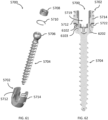
- FIG. 19 illustrates an exploded view of the bone anchor assembly 100.
- the bone anchor 100 can be assembled by top loading or distally advancing the spring clip or ring 204 relative to the receiver member 102 and allowing the spring clip/ring 204 to expand into the groove 1702.
- the shank 104 can then be top loaded or advanced distally through the interior of the receiver member 102 such that the distal bone-engaging portion 108 of the shank 104 extends out the through-hole 101 (shown in FIG.
- the compression cap 202 can also be top loaded or distally advanced into the interior of the receiver member 102, and a swaging operation can be performed to lock the compression cap 202 against removal from the interior of the receiver member 102.
- the compression cap 202 can still translate through a range of motion relative to the receiver member 102 and shank 104, such polyaxial movement of the receiver member 102 relative to the shank 104 can be selectively controlled by varying distal force placed on the compression cap 202 that drives it into frictional contact with the proximal end of the bone shank spherical head 302.
- FIGS. 20-56 illustrate additional embodiments of bone anchor assemblies according to the present disclosure. These embodiments utilize many of the above-described features but can be configured for use with larger diameter screw shanks.
- the receiver members shown in these embodiments can be configured to bias shank angulation to one side or in one direction using a "favored angle" distal portion that allows a greater degree of shank angulation in one direction versus the opposite direction.
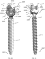
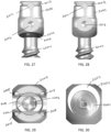
- FIGS. 20-34 illustrate different views of one embodiment of a large diameter favored angle bone anchor assembly 2000 according to the present disclosure
- FIGS. 35-45 illustrate detail views of components of the assembly. More particularly, FIGS. 20 and 21 provide opposing perspective views of a bone anchor assembly 2000.
- FIG. 22 provides an exploded view of the bone anchor assembly 2000.
- FIG. 23 provides a cross-sectional view of the bone anchor assembly 2000.
- FIG. 24 provides a partially transparent perspective view of the proximal portion of the bone anchor assembly 2000.
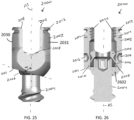
- FIG. 25 provides a front view of the proximal portion of the bone anchor assembly 2000.
- FIG. 26 provides a front cross-sectional view of the proximal portion of the bone anchor assembly 2000.
- the receiver member 2002 can additionally or alternatively include a distal rocker feature (also referred to as a second recess) 2016.
- the distal rocker feature 2016 can be formed in the receiver member 2002 at a position distal to the proximal rocker feature 2014.
- the second or distal rocker feature 2016 can provide an alternative coupling position for a rocker instrument, such as a reducer rocker fork, to the proximal rocker feature 2014.
- the second rocker feature can also be a swage feature used to retain a compression member 2008 within the receiver member 2002.
- a swaging process can form the second rocker feature 2016 and displace receiver member material into a recess 4202 (see FIG.
- the receiver member 2002 can include at least one unilateral attachment feature 2018 that can enable a surgical instrument to couple to or engage with the receiver member 2002 in a manner that leaves the rod-receiving slot 2019 unobstructed, e.g., by allowing attachment of an instrument to the receiver member 2002 by engaging only one arm 2013 or 2015 of the receiver member 2002.
- the receiver member 2002 can include a unilateral attachment feature 2018 on four proximal quadrants of the receiver member 2002.
- a unilateral attachment feature 2018 can be formed on opposing laterally-facing edges of each of the spaced apart arms 2013, 2015.
- a surgical instrument can attach to two adjacent unilateral features 2018 on one side of the receiver member 2002, leaving the rod-receiving slot 2019 open to receive a spinal fixation rod and/or set screw introduced distally from the proximal end 2009 of the receiver member 2002, as explained above.
- the receiver member 2002 can receive spinal fixation elements of multiple sizes.
- spinal rods having a diameter of about 5.5 mm or a diameter of about 6.0 mm can be received within the rod-receiving recess 2019.
- a proximal portion of the spaced apart arms 2013, 2015 of the receiver member 2002 can include a threaded inner surface 2020 that can engage with a set screw or other locking element received therebetween to lock a spinal rod within the receiver member 2002.
- the inner threaded portion 2020 can have square threads e.g., to engage with counterpart external square threads of a set screw (e.g., see FIG. 14 ).
- the receiver member 2002 can also include a taper in at least one direction.
- FIG. 33 is a partially transparent view of the bone anchor assembly 2000 of FIG. 20 that shows, among other things, a taper 3302 of the outer surface of the receiver member 2002 in a first direction. More particularly, a first pair of opposed sides 3304, 3306, shown in FIG. 33 as exterior walls of the spaced-apart arms 2013, 2015, can have a first taper with respect to a first plane that contains a proximal-distal axis A1 of the receiver member (i.e., the plane of the page of FIG. 33 ). As shown above in FIG. 7 , a second taper can be included in an orientation that is 90 degrees offset from the orientation shown in FIG.
- the bone anchor assembly 2000 does not include a second taper.
- the surfaces 2030, 2031 adjacent planar tapered surfaces 3304, 3306 have a straight cylindrical profile.
- the first plane and the second plane can be perpendicular to one another in some embodiments, though other offset angles are also possible.
- the receiver member 2002 when implanted into a patient's spine, can have walls that taper in both the cephalad-caudal direction and the medial-lateral direction, for example. Taper of the receiver member 2002 with respect to one or two offset planes can aid in instrument attachment to the receiver member as the angled characteristic of the receiver member, i.e., the tapering of exterior walls or an outer surface of the receiver member in one or two directions, can guide surgical instruments to self-center during attachment to the receiver member.
- the receiver member can be configured to provide a greater degree of angulation in a first direction relative to a second direction that is opposite the first direction.
- the receiver member 2002 can include a distal facing surface 2022 that is obliquely angled relative to a central proximal-distal axis A1 of the receiver member. This can effectively angle a hole 2202 (see FIG. 22 ) formed in the distal facing surface of the receiver member 2002 to one side, thereby allowing a greater degree of angulation of the bone anchor 2004 toward that side in comparison to an opposite side. This can bias the bone anchor assembly 2000 to favor angulation in one direction.
- FIG. 25 illustrates the angle ⁇ created between the central proximal-distal axis A1 and the plane of the distal facing surface 2022.
- the bone anchor or shank 2004 can similarly include any of the various features described above.
- the bone anchor 2004 can include external threads 2024 extending along the bone-engaging portion 2007 of the shank 2004.
- Various thread forms can be utilized for shanks of the present disclosure, including solid dual lead, solid cortical fix, cannulated dual lead, cannulated cortical fix, and cannulated cortical fix fenestrated threads.
- the bone shank 2004 can have a quick-start tip 3402, as shown in FIG 34 , with threads that extend distally to a distal tip 3410 of the bone engaging portion 2007. In this manner, the threads 2024 can extend to the contact surface between the bone shank 2004 and the bone, which can provide immediate purchase of the thread 2024 into bone.
- a recess 3404 can be centered and formed in the distal tip of the bone shank 2004.
- This recess 3404 which can be referred to as a centering recess, can be used to support the distal bone-engaging portion 2007 of the shank 2004 in a centered manner during the manufacturing process.
- the centering recess 3404 can be a blind bore that extends proximally from the distal tip of the bone-engaging portion (e.g., as shown in the partially transparent view of FIG. 34 ).
- the centering recess 3404 can be a full cannulated recess that extends from the proximal end to the distal end of the bone shank 2004. Such a recess can allow, for example, for introduction of the shank 2004 over a guidewire, delivery of cement or other flowable material through the shank 2004 into bone, etc.
- a drive feature 2302 (see FIGS. 23 and 29 ) can be formed in the proximal head 2204 of the bone shank 2004 to allow a driver to control rotation of the anchor during implantation, etc. Any of a variety of drive feature designs can be utilized, including square drive, hex drive, lobed drives, etc.
- the illustrated embodiment includes a T27 drive feature.
- the bone anchor assembly 2000 can be configured for use with larger diameter bone anchors or shanks 2004.
- the bone anchor assembly 100 described above can have a bone anchor 104 with a shank diameter of up to about 7 mm. Above about that size, the bone anchor can become too large for bottom loading through the hole formed in the distal surface of the receiver member, especially when the bone anchor includes a spherically-shaped proximal end.
- the bone anchor assembly 2000 can provide for larger size bone anchors by utilizing a bone anchor with a relatively uniform diameter or column-shaped proximal end that can be bottom loaded into the receiver member 2002 through the hole 2202 and coupled to a locking sphere 2006 that is top loaded into the receiver member.
- This modular configuration can allow, in some embodiments, the use of bone anchors with a diameter between about 7 mm and about 12 mm, though this configuration could also be used for any smaller diameter in place of a single-component bone anchor like that shown in the embodiment of FIG. 1 .
- the bone anchor 2004 can include a proximal portion 2204 configured to couple with the locking sphere 2006.
- the proximal portion 2204 can include a rib, protrusion, or other feature 2206 formed on an outer surface thereof that can interface with a recess or other complementary feature 4002 (see FIG. 40 ) formed on an inner surface of the locking sphere 2006.
- This arrangement can secure the locking sphere 2006 relative to the bone anchor 2004 such that the bone anchor 2004 can move polyaxially relative to the receiver member 2002 when the locking sphere 2006 is disposed in the polyaxial seat 2019 of the receiver member 2002. Further, movement of the bone anchor 2004 relative to the receiver member 2002 can be controlled using friction forces exerted on the locking sphere 2006, as explained in more detail below.
- the locking sphere 2006 can have a spherical outer surface and a columnar inner surface configured to receive the proximal end portion 2204 of the bone anchor 2004.
- the locking sphere 2006 can also include one or more relief slits 3902 formed therein to allow for deformation of the locking sphere 2006 when coupling with the bone anchor 2004.
- two different shapes of relief slits 3902, 3904 are provided in an alternating pattern around the circumference of the locking sphere 2006.
- the inner surface of the locking sphere 2006 can include the recess 4002 that can receive the rib 2206 formed on the outer surface of the proximal portion 2204 of the bone anchor 2004 to help secure the two components relative to one another when coupled.
- two planar surfaces 4204, 4206 of the compression member can be angularly offset from one another to form a substantially "V" shaped groove that can seat a spinal rod of varying diameters.
- a bottom surface 4208 of the compression member 2008 can include a substantially spherical surface configured to contact the locking sphere 2006 and exert a friction force thereon when the compression member 2008 is advanced distally relative to the receiver member 2002 (e.g., by a user tightening a set screw into the threads formed in the proximal portion of the receiver member).
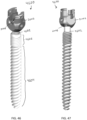
- FIGS. 46-49 illustrate different views of another embodiment of a large diameter favored angle bone anchor assembly 4600 according to the present disclosure. More particularly, FIGS. 46 and 47 provide opposing perspective views of a bone anchor assembly 4600.
- FIG. 48 provides an exploded view of the bone anchor assembly 4600.
- FIG. 49 provides a cross-sectional view of the bone anchor assembly 4600.
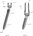
- the bone anchor 4602 can include a plurality of threaded sections that can be configured to increase fixation of the bone anchor assembly 4600 in bone.
- the bone anchor 4602 can include a first distal threaded section 4604 that has a first pitch and a first number of thread starts and a second proximal threaded section 4606 that has a second pitch less than the first pitch and a second number of thread starts greater than the first number of thread starts.
- the receiver head 2002, locking sphere 2006, compression member 2008, and drag ring 2010 can be the same as those described above in connection with the embodiments of FIGS. 20 and 46 , but a differently-configured bone anchor or shank 5002 can be provided.
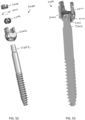
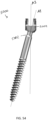
- the bone anchor 5002 can include a first, distal threaded portion or section 5004 and a second portion or section 5006 without threads that is disposed between the first portion 5004 and the proximal portion 5007 of the bone anchor 5002.
- the bone anchor 5002 can be useful in certain applications where a longer screw with maximum strength is desirable.
- One such application is in "SAI" trajectories, i.e., procedures where the bone anchor is introduced through the sacral alar such that its distal end arrives in the ilium.
- SAI trajectories
- the unthreaded second portion 5006 can be provided that has a diameter just under that of the maximum major diameter of the threaded first portion 5004.
- FIG. 54 illustrates the bone anchor assembly 5000 in an angulated state, where a proximal-distal axis A1 of the receiver member 2002 is obliquely angled relative to a proximal-distal axis A2 of the bone anchor 5002. This is in contrast to the positioning shown in FIGS. 50-53 where the axes A1 and A2 are aligned and coaxial with one another.
- the "favored angle" configuration of the receiver member 2002 can allow a greater degree of angulation in one direction versus a second opposite direction. For example, a greater degree of angulation in the direction shown in FIG.
- the bone anchor 5502 can include one or more outlets 5504 formed along a length thereof that can intersect with the cannula or passage formed in the bone anchor.
- the one or more outlets 5504 can allow a flowable substance, e.g., a bone cement or other substance, to be introduced into the area surrounding the bone anchor by injecting it into the cannula or passage at the proximal end of the bone anchor.
- the one or more outlets 5504 can be disposed along any portion of the bone anchor 5502. In the illustrated embodiment, the outlets 5504 are shown disposed along a distal portion of the bone anchor 5502 with opposed outlets forming a through-bore in the bone anchor that intersects the central cannula or passage formed in the bone anchor. In some embodiments, the laterally-facing outlets 5504 can be omitted such that the bone anchor 5502 includes a single cannula extending from openings formed at its proximal end 5508 and its distal end 5506.
- FIG. 56 illustrates another embodiment of a large diameter favored angle bone anchor assembly 5600 according to the present disclosure.
- the locking sphere 2006, compression member 2008, drag ring 2010, and bone anchor 2004 are the same as those described above in connection with the embodiment of FIG. 20 , but a differently-configured receiver head 5602 is provided.
- the receiver member 5602 can include one or more extended tabs 5604 protruding from a proximal end of the receiver head to facilitate manipulation of the receiver head and introduction of components, such as a set screw or other instrument or component to help reduce and secure a rod in position relative to the receiver member 5602.
- the one or more tabs 5604 can be integrally formed with the receiver member 5602 or otherwise coupled thereto.
- extended tabs can be included with any of the various embodiments described herein.
- one or more extended tabs can be included in the receiver members of the embodiments of any of FIGS. 46 and 50 as well.
- FIGS. 57-62 illustrate different views of one embodiment of a bone anchor assembly 5700 according to the present disclosure
- FIGS. 63-66 illustrate detail views of a compression cap of the assembly. More particularly, FIGS. 57 and 58 provide opposing perspective views of a bone anchor assembly 5700.
- FIGS. 59A , 59B , and 60 provide detail views of a proximal portion of the assembly
- FIG. 61 provides an exploded view of the bone anchor assembly 5700
- FIG. 62 provides a cross-sectional view of the bone anchor assembly 5700.
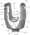
- the receiver member 5702 of bone anchor assembly 5700 can include a proximal end 5703 defined by a pair of spaced apart arms 5712, 5714 forming a U-shaped recess 5719 (also referred to as a rod-receiving recess or slot) therebetween to receive a spinal fixation element (not shown), such as a spinal rod.
- a polyaxial seat 6202 can be formed in a distal end 5711 of the receiver member 5702 for polyaxially seating a proximal portion 5706 of the bone anchor/shank 5704.
- the bone anchor assembly 5700 can further include a compression member or cap 5708 and a drag ring 5710 disposed within the receiver member 5702, each of which can contact the proximal portion 5706 to exert friction forces thereon that can selectively resist and/or prevent any relative movement of the receiver member 5702 relative to the bone anchor 5704.
- FIG. 60 illustrates that the receiver member 5702 includes a first set of opposed sides, 6004, 6006, having a substantially straight cylindrical profile without any taper in diameter along a longitudinal axis of the receiver member 5702.
- a second set of opposed sides offset from the first sides 6004, 6006, can be planar and include a taper such that a distance between the second set of opposed sides decreases moving proximally along the longitudinal axis of the receiver member 5702.
- the first of the opposed sides 7004 (opposed side 7006 is hidden from view opposite side 7004) can be seen in FIGS. 59A and 59B , and their configuration is similar to that shown in FIG. 7 .
- FIGS. 63-66 illustrate a compression member or cap 5708 of the assembly 5700.
- FIGS. 63 and 64 are perspective views of one embodiment of a compression member 5708,
- FIG. 65 is a front view of the compression member 5708,
- FIG. 66 is a front cross-sectional view of the compression member 5708.
- the outer surface of the compression cap 5708 can receive material from the receiver member 5702 that is displaced during a swage that can form the second rocker feature 5722.
- the configuration of the compression cap 5708 is different from the compression cap 202, however, in that it includes opposed flat surfaces 6102 rather than recesses 304.
- the opposed flat surfaces 6102 can simplify manufacturing and allow a larger surface area for contact.
- the opposed flat surfaces 6102 can be recessed relative to a maximum outer diameter of the compression cap 5708 and a protruding lip 6103 can be formed distal to the opposed flat surfaces. Accordingly, displaced material from the receiver member 5702 that is moved inward during a swage operation can abut the opposed flat surfaces 6102 and prevent the compression cap 5708 from being removed proximally out of the receiver member by interfering with the lip 6103. Distal advancement of the compression cap 5708 remains possible during, e.g., locking where a set screw is tightened onto a rod disposed in the slot 5719.
- the configuration of the opposed flat surfaces 6102 and the receiver member 5702 can be seen in the cross-sectional view of FIG. 62 .
- a bottom surface 6108 of the compression member 5708 can include a substantially spherical surface configured to contact the locking sphere 5706 and exert a friction force thereon when the compression member 5708 is advanced distally relative to the receiver member 5702 (e.g., by a user tightening a set screw into the threads formed in the proximal portion of the receiver member).
- phrases “at least one of A, B, and C,” “one or more of A, B, and C,” and “A, B, and/or C” are each intended to mean “A alone, B alone, C alone, A and B together, A and C together, B and C together, or A and B and C together.”
- use of the term “based on,” is intended to mean, “based at least in part on,” such that an un-recited feature or element is also permissible.
Landscapes
- Health & Medical Sciences (AREA)
- Orthopedic Medicine & Surgery (AREA)
- Life Sciences & Earth Sciences (AREA)
- Surgery (AREA)
- Neurology (AREA)
- Heart & Thoracic Surgery (AREA)
- General Health & Medical Sciences (AREA)
- Biomedical Technology (AREA)
- Nuclear Medicine, Radiotherapy & Molecular Imaging (AREA)
- Medical Informatics (AREA)
- Molecular Biology (AREA)
- Animal Behavior & Ethology (AREA)
- Engineering & Computer Science (AREA)
- Public Health (AREA)
- Veterinary Medicine (AREA)
- Surgical Instruments (AREA)
- Polyesters Or Polycarbonates (AREA)
- Pharmaceuticals Containing Other Organic And Inorganic Compounds (AREA)
- Extrusion Moulding Of Plastics Or The Like (AREA)
Applications Claiming Priority (4)
| Application Number | Priority Date | Filing Date | Title |
|---|---|---|---|
| US202163157362P | 2021-03-05 | 2021-03-05 | |
| US202163221359P | 2021-07-13 | 2021-07-13 | |
| PCT/EP2022/055325 WO2022184796A1 (en) | 2021-03-05 | 2022-03-02 | Multi-feature polyaxial screw |
| EP22712329.6A EP4301257B1 (de) | 2021-03-05 | 2022-03-02 | Polyaxiale schraube mit mehreren merkmalen |
Related Parent Applications (2)
| Application Number | Title | Priority Date | Filing Date |
|---|---|---|---|
| EP22712329.6A Division EP4301257B1 (de) | 2021-03-05 | 2022-03-02 | Polyaxiale schraube mit mehreren merkmalen |
| EP22712329.6A Division-Into EP4301257B1 (de) | 2021-03-05 | 2022-03-02 | Polyaxiale schraube mit mehreren merkmalen |
Publications (2)
| Publication Number | Publication Date |
|---|---|
| EP4534036A2 true EP4534036A2 (de) | 2025-04-09 |
| EP4534036A3 EP4534036A3 (de) | 2025-06-25 |
Family
ID=80933315
Family Applications (3)
| Application Number | Title | Priority Date | Filing Date |
|---|---|---|---|
| EP25159408.1A Pending EP4534036A3 (de) | 2021-03-05 | 2022-03-02 | Polyaxiale schraube mit mehreren merkmalen |
| EP22712551.5A Pending EP4301259A1 (de) | 2021-03-05 | 2022-03-02 | Polyaxiale schraube mit mehreren merkmalen |
| EP22712329.6A Active EP4301257B1 (de) | 2021-03-05 | 2022-03-02 | Polyaxiale schraube mit mehreren merkmalen |
Family Applications After (2)
| Application Number | Title | Priority Date | Filing Date |
|---|---|---|---|
| EP22712551.5A Pending EP4301259A1 (de) | 2021-03-05 | 2022-03-02 | Polyaxiale schraube mit mehreren merkmalen |
| EP22712329.6A Active EP4301257B1 (de) | 2021-03-05 | 2022-03-02 | Polyaxiale schraube mit mehreren merkmalen |
Country Status (5)
| Country | Link |
|---|---|
| US (3) | US12310631B2 (de) |
| EP (3) | EP4534036A3 (de) |
| JP (2) | JP2024508173A (de) |
| AU (2) | AU2022230734A1 (de) |
| WO (2) | WO2022184799A1 (de) |
Families Citing this family (8)
| Publication number | Priority date | Publication date | Assignee | Title |
|---|---|---|---|---|
| US10625906B1 (en) * | 2018-11-16 | 2020-04-21 | Stasher, Inc. | Inside out method of manufacturing a container with a leak resistant seal |
| WO2021127251A1 (en) * | 2019-12-17 | 2021-06-24 | Jackson Roger P | Bone anchor assembly with closed ring retainer and internal snap ring |
| AU2022230734A1 (en) | 2021-03-05 | 2023-10-19 | Medos International Sarl | Multi-feature polyaxial screw |
| WO2024056761A1 (en) | 2022-09-13 | 2024-03-21 | Medos International Sarl | Modular connector assemblies |
| JP2024144191A (ja) * | 2023-03-30 | 2024-10-11 | ビーダーマン・テクノロジーズ・ゲゼルシャフト・ミット・ベシュレンクテル・ハフツング・ウント・コンパニー・コマンディートゲゼルシャフト | ロッドを骨アンカーに連結するための連結装置ならびにそのような連結装置および少なくとも2つの骨アンカーからなるシステム |
| WO2025082962A1 (en) | 2023-10-16 | 2025-04-24 | Medos International Sarl | Combination derotation and reducer instruments |
| US20250186093A1 (en) | 2023-12-08 | 2025-06-12 | Medos International Sàrl | Surgical instruments and methods for separating implants from other components |
| EP4686453A1 (de) * | 2024-08-01 | 2026-02-04 | Biedermann Technologies GmbH & Co. KG | Aufnahmeteil einer knochenverankerungsvorrichtung und system aus mindestens einem instrument und einem aufnahmeteil |
Citations (5)
| Publication number | Priority date | Publication date | Assignee | Title |
|---|---|---|---|---|
| US7087057B2 (en) | 2003-06-27 | 2006-08-08 | Depuy Acromed, Inc. | Polyaxial bone screw |
| US9155580B2 (en) | 2011-08-25 | 2015-10-13 | Medos International Sarl | Multi-threaded cannulated bone anchors |
| US10039578B2 (en) | 2003-12-16 | 2018-08-07 | DePuy Synthes Products, Inc. | Methods and devices for minimally invasive spinal fixation element placement |
| US10299839B2 (en) | 2003-12-16 | 2019-05-28 | Medos International Sárl | Percutaneous access devices and bone anchor assemblies |
| US20190183541A1 (en) | 2017-12-15 | 2019-06-20 | Medos International Sarl | Unilateral implant holders and related methods |
Family Cites Families (248)
| Publication number | Priority date | Publication date | Assignee | Title |
|---|---|---|---|---|
| DE3614101C1 (de) | 1986-04-25 | 1987-10-22 | Juergen Prof Dr Med Harms | Pedikelschraube |
| DE4243951C2 (de) | 1992-12-23 | 1997-07-03 | Plus Endoprothetik Ag | Vorrichtung zur Versteifung eines aus wenigstens zwei Wirbeln bestehenden Wirbelsäulenabschnitts |
| DE4307576C1 (de) | 1993-03-10 | 1994-04-21 | Biedermann Motech Gmbh | Knochenschraube |
| US5961517A (en) | 1994-07-18 | 1999-10-05 | Biedermann; Lutz | Anchoring member and adjustment tool therefor |
| DE19509332C1 (de) | 1995-03-15 | 1996-08-14 | Harms Juergen | Verankerungselement |
| US5733285A (en) | 1995-07-13 | 1998-03-31 | Fastenetix, Llc | Polyaxial locking mechanism |
| US5879350A (en) | 1996-09-24 | 1999-03-09 | Sdgi Holdings, Inc. | Multi-axial bone screw assembly |
| US5885286A (en) | 1996-09-24 | 1999-03-23 | Sdgi Holdings, Inc. | Multi-axial bone screw assembly |
| US5728098A (en) | 1996-11-07 | 1998-03-17 | Sdgi Holdings, Inc. | Multi-angle bone screw assembly using shape-memory technology |
| KR100417222B1 (ko) | 1996-12-12 | 2004-02-05 | 신테스 아게 츄어 | 페디클 스크류와 횡방향 지지대를 연결하기 위한 장치 |
| US5782833A (en) | 1996-12-20 | 1998-07-21 | Haider; Thomas T. | Pedicle screw system for osteosynthesis |
| DE59712497D1 (de) | 1997-01-22 | 2005-12-29 | Synthes Ag | Vorrichtung zur verbindung eines langsträgers mit einer pedikelschraube |
| US5733286A (en) | 1997-02-12 | 1998-03-31 | Third Millennium Engineering, Llc | Rod securing polyaxial locking screw and coupling element assembly |
| US6248105B1 (en) | 1997-05-17 | 2001-06-19 | Synthes (U.S.A.) | Device for connecting a longitudinal support with a pedicle screw |
| US5891145A (en) | 1997-07-14 | 1999-04-06 | Sdgi Holdings, Inc. | Multi-axial screw |
| US6010503A (en) | 1998-04-03 | 2000-01-04 | Spinal Innovations, Llc | Locking mechanism |
| FR2778089B1 (fr) | 1998-04-30 | 2000-07-21 | Dimso Sa | Systeme d'osteosynthese rachidienne avec bride et verrou |
| US6113601A (en) | 1998-06-12 | 2000-09-05 | Bones Consulting, Llc | Polyaxial pedicle screw having a loosely coupled locking cap |
| US6090111A (en) | 1998-06-17 | 2000-07-18 | Surgical Dynamics, Inc. | Device for securing spinal rods |
| EP1117336B1 (de) | 1998-09-29 | 2004-05-19 | SYNTHES AG Chur | Vorrichtung zur verbindung eines längsträgers mit einem knochenfixationsmittel |
| US6254602B1 (en) | 1999-05-28 | 2001-07-03 | Sdgi Holdings, Inc. | Advanced coupling device using shape-memory technology |
| FR2794637B1 (fr) | 1999-06-14 | 2001-12-28 | Scient X | Implant pour dispositif d'osteosynthese notamment du rachis |
| FR2796545B1 (fr) | 1999-07-22 | 2002-03-15 | Dimso Sa | Liaison poly-axiale pour systeme d'osteosynthese, notamment pour le rachis |
| DE19936286C2 (de) | 1999-08-02 | 2002-01-17 | Lutz Biedermann | Knochenschraube |
| ES2153331B1 (es) | 1999-08-05 | 2001-09-01 | Traiber S A | Sistema de fijacion intervertebral para tratamientos de columna. |
| US6280442B1 (en) | 1999-09-01 | 2001-08-28 | Sdgi Holdings, Inc. | Multi-axial bone screw assembly |
| CA2423973A1 (en) | 1999-09-27 | 2001-04-05 | Blackstone Medical, Inc. | A surgical screw system and related methods |
| DE10005385A1 (de) | 2000-02-07 | 2001-08-09 | Ulrich Gmbh & Co Kg | Pedikelschraube |
| DE10005386A1 (de) | 2000-02-07 | 2001-08-09 | Ulrich Gmbh & Co Kg | Pedikelschraube |
| US6485491B1 (en) * | 2000-09-15 | 2002-11-26 | Sdgi Holdings, Inc. | Posterior fixation system |
| US6755829B1 (en) | 2000-09-22 | 2004-06-29 | Depuy Acromed, Inc. | Lock cap anchor assembly for orthopaedic fixation |
| DE10055888C1 (de) * | 2000-11-10 | 2002-04-25 | Biedermann Motech Gmbh | Knochenschraube |
| AU2002235349B2 (en) | 2001-01-12 | 2006-05-18 | Depuy Spine, Inc. | Polyaxial screw with improved locking |
| DE10115014A1 (de) | 2001-03-27 | 2002-10-24 | Biedermann Motech Gmbh | Verankerungselement |
| US8353932B2 (en) * | 2005-09-30 | 2013-01-15 | Jackson Roger P | Polyaxial bone anchor assembly with one-piece closure, pressure insert and plastic elongate member |
| US6974460B2 (en) | 2001-09-14 | 2005-12-13 | Stryker Spine | Biased angulation bone fixation assembly |
| FR2830433B1 (fr) | 2001-10-04 | 2005-07-01 | Stryker Spine | Ensemble pour l'osteosynthese du rachis comprenant une tete d'organe d'ancrage et un outil pour la fixation de la tete |
| KR100379194B1 (en) | 2001-10-31 | 2003-04-08 | U & I Co Ltd | Apparatus for fixing bone |
| DE10157969C1 (de) | 2001-11-27 | 2003-02-06 | Biedermann Motech Gmbh | Element mit einem Schaft und einem damit verbundenen Halteelement zum Verbinden mit einem Stab |
| CN1432343A (zh) | 2002-01-17 | 2003-07-30 | 英属维京群岛商冠亚生技控股集团股份有限公司 | 脊椎固定用旋控式固定装置 |
| US7066937B2 (en) | 2002-02-13 | 2006-06-27 | Endius Incorporated | Apparatus for connecting a longitudinal member to a bone portion |
| US7879075B2 (en) | 2002-02-13 | 2011-02-01 | Zimmer Spine, Inc. | Methods for connecting a longitudinal member to a bone portion |
| US6837889B2 (en) | 2002-03-01 | 2005-01-04 | Endius Incorporated | Apparatus for connecting a longitudinal member to a bone portion |
| ES2629431T3 (es) | 2002-10-30 | 2017-08-09 | Zimmer Spine, Inc. | Sistema de estabilización espinal por inserción |
| FR2847152B1 (fr) | 2002-11-19 | 2005-02-18 | Eurosurgical | Dispositif d'ancrage vertebral et son dispositif de blocage sur une vis poly axiale |
| US20110040338A1 (en) | 2003-08-28 | 2011-02-17 | Jackson Roger P | Polyaxial bone anchor having an open retainer with conical, cylindrical or curvate capture |
| US7776067B2 (en) | 2005-05-27 | 2010-08-17 | Jackson Roger P | Polyaxial bone screw with shank articulation pressure insert and method |
| US7967850B2 (en) | 2003-06-18 | 2011-06-28 | Jackson Roger P | Polyaxial bone anchor with helical capture connection, insert and dual locking assembly |
| US8814911B2 (en) * | 2003-06-18 | 2014-08-26 | Roger P. Jackson | Polyaxial bone screw with cam connection and lock and release insert |
| AU2004266737B2 (en) | 2003-08-20 | 2010-05-13 | Warsaw Orthopedic, Inc. | Multi-axial orthopedic device and system, e.g. for spinal surgery |
| DE102004010380A1 (de) * | 2004-03-03 | 2005-09-22 | Biedermann Motech Gmbh | Verankerungselement und Stabilisierungseinrichtung zur dynamischen Stabilisierung von Wirbeln bzw. Knochen mit einem solchen Verankerungselement |
| US7717939B2 (en) | 2004-03-31 | 2010-05-18 | Depuy Spine, Inc. | Rod attachment for head to head cross connector |
| US8475495B2 (en) | 2004-04-08 | 2013-07-02 | Globus Medical | Polyaxial screw |
| US7857834B2 (en) | 2004-06-14 | 2010-12-28 | Zimmer Spine, Inc. | Spinal implant fixation assembly |
| US7766945B2 (en) | 2004-08-10 | 2010-08-03 | Lanx, Inc. | Screw and rod fixation system |
| US7186255B2 (en) | 2004-08-12 | 2007-03-06 | Atlas Spine, Inc. | Polyaxial screw |
| US20060058788A1 (en) | 2004-08-27 | 2006-03-16 | Hammer Michael A | Multi-axial connection system |
| US8951290B2 (en) | 2004-08-27 | 2015-02-10 | Blackstone Medical, Inc. | Multi-axial connection system |
| US7691129B2 (en) | 2004-10-27 | 2010-04-06 | Felix Brent A | Spinal stabilizing system |
| US8444681B2 (en) | 2009-06-15 | 2013-05-21 | Roger P. Jackson | Polyaxial bone anchor with pop-on shank, friction fit retainer and winged insert |
| US20130144346A1 (en) * | 2004-11-23 | 2013-06-06 | Roger P. Jackson | Modular polyaxial bone anchor with retainer having interconnected pieces |
| US9168069B2 (en) | 2009-06-15 | 2015-10-27 | Roger P. Jackson | Polyaxial bone anchor with pop-on shank and winged insert with lower skirt for engaging a friction fit retainer |
| US9980753B2 (en) | 2009-06-15 | 2018-05-29 | Roger P Jackson | pivotal anchor with snap-in-place insert having rotation blocking extensions |
| US20140121703A1 (en) * | 2012-10-31 | 2014-05-01 | Roger P. Jackson | Polyaxial bone anchor with pop-on multi-thread shank, some with diametric interference fit inserts |
| US7811288B2 (en) | 2004-12-02 | 2010-10-12 | Zimmer Spine, Inc. | Instruments and methods for adjusting separation distance of vertebral bodies with a minimally invasive spinal stabilization procedure |
| EP1871302A4 (de) | 2005-03-25 | 2012-05-02 | Blackstone Medical Inc | Multiaxiales verbindungssystem |
| ES2333728T3 (es) | 2005-07-08 | 2010-02-26 | Biedermann Motech Gmbh | Dispositivo de anclaje oseo. |
| US8100916B2 (en) | 2005-07-21 | 2012-01-24 | Depuy Spine, Inc. | Instrument for inserting, adjusting and removing a surgical implant |
| US7988694B2 (en) | 2005-09-29 | 2011-08-02 | K2M, Inc. | Spinal fixation system having locking and unlocking devices for use with a multi-planar, taper lock screw |
| WO2007041698A1 (en) | 2005-10-04 | 2007-04-12 | Alphaspine, Inc. | Modular pedicle screw systems and methods of intra-operatively assembling the same |
| DE602005009202D1 (de) | 2005-10-12 | 2008-10-02 | Biedermann Motech Gmbh | In nur einer Ebene schwenkbare Polyaxialschraube |
| US20070161998A1 (en) | 2005-10-28 | 2007-07-12 | Dale Whipple | Instruments and Methods For Manipulating A Spinal Rod |
| US8100946B2 (en) | 2005-11-21 | 2012-01-24 | Synthes Usa, Llc | Polyaxial bone anchors with increased angulation |
| US7833252B2 (en) | 2006-01-27 | 2010-11-16 | Warsaw Orthopedic, Inc. | Pivoting joints for spinal implants including designed resistance to motion and methods of use |
| US20070270806A1 (en) | 2006-04-07 | 2007-11-22 | Foley Kevin T | Devices and methods for receiving elongated connecting elements in spinal surgical procedures |
| US20080015597A1 (en) | 2006-04-28 | 2008-01-17 | Whipple Dale E | Large diameter bone anchor assembly |
| US8133262B2 (en) | 2006-04-28 | 2012-03-13 | Depuy Spine, Inc. | Large diameter bone anchor assembly |
| US7922748B2 (en) | 2006-06-16 | 2011-04-12 | Zimmer Spine, Inc. | Removable polyaxial housing for a pedicle screw |
| US8162991B2 (en) | 2006-07-27 | 2012-04-24 | K2M, Inc. | Multi-planar, taper lock screw |
| BRPI0715218A2 (pt) | 2006-08-01 | 2013-06-18 | Warsaw Orthopedic Inc | elemento de ancoragem àssea e dispositivo para corrigir deformaÇÕes da coluna vertebral |
| US8016862B2 (en) * | 2006-09-27 | 2011-09-13 | Innovasis, Inc. | Spinal stabilizing system |
| US8167910B2 (en) * | 2006-10-16 | 2012-05-01 | Innovative Delta Technology Llc | Bone screw and associated assembly and methods of use thereof |
| US7699876B2 (en) | 2006-11-08 | 2010-04-20 | Ebi, Llc | Multi-axial bone fixation apparatus |
| US8211110B1 (en) | 2006-11-10 | 2012-07-03 | Lanx, Inc. | Minimally invasive tool to facilitate implanting a pedicle screw and housing |
| ATE551962T1 (de) | 2006-11-22 | 2012-04-15 | Biedermann Motech Gmbh | Knochenverankerungsvorrichtung |
| US8231635B2 (en) | 2007-01-18 | 2012-07-31 | Stryker Spine | Polyaxial screwdriver for a pedicle screw system |
| US20080200956A1 (en) | 2007-02-19 | 2008-08-21 | Tutela Medicus, Llc | Low Profile Orthopedic Fastener Assembly Having Enhanced Flexibility |
| US8926669B2 (en) | 2007-02-27 | 2015-01-06 | The Center For Orthopedic Research And Education, Inc. | Modular polyaxial pedicle screw system |
| US7967849B2 (en) | 2007-04-06 | 2011-06-28 | Warsaw Orthopedic, Inc. | Adjustable multi-axial spinal coupling assemblies |
| US8197517B1 (en) | 2007-05-08 | 2012-06-12 | Theken Spine, Llc | Frictional polyaxial screw assembly |
| US7951173B2 (en) | 2007-05-16 | 2011-05-31 | Ortho Innovations, Llc | Pedicle screw implant system |
| US7942910B2 (en) | 2007-05-16 | 2011-05-17 | Ortho Innovations, Llc | Polyaxial bone screw |
| US20090118772A1 (en) | 2007-06-01 | 2009-05-07 | Jennifer Diederich | Polyaxial bone anchor with increased angulation |
| US8043343B2 (en) | 2007-06-28 | 2011-10-25 | Zimmer Spine, Inc. | Stabilization system and method |
| EP2170192B1 (de) | 2007-07-20 | 2011-02-09 | Synthes GmbH | Mehrachsiges Knochenfixierungselement |
| US9439681B2 (en) | 2007-07-20 | 2016-09-13 | DePuy Synthes Products, Inc. | Polyaxial bone fixation element |
| US8038701B2 (en) | 2007-10-22 | 2011-10-18 | K2M, Inc. | Uni-planar, taper lock bone screw |
| US8398683B2 (en) | 2007-10-23 | 2013-03-19 | Pioneer Surgical Technology, Inc. | Rod coupling assembly and methods for bone fixation |
| US20110087288A1 (en) | 2007-10-24 | 2011-04-14 | Tara Stevenson | Surgical Fixation System and Related Methods |
| US7789900B2 (en) | 2007-12-04 | 2010-09-07 | Expanding Orthopedics, Inc. | Double collet connector assembly for bone anchoring element |
| ES2373690T3 (es) | 2007-12-13 | 2012-02-07 | Biedermann Motech Gmbh | Dispositivo de anclaje para anclar una varilla en un hueso o vértebra. |
| EP2111811B1 (de) * | 2008-04-22 | 2011-06-15 | BIEDERMANN MOTECH GmbH | Instrument zur Montage einer Knochenverankerungsvorrichtung |
| WO2009155523A1 (en) | 2008-06-19 | 2009-12-23 | Life Spine, Inc. | Spinal rod connectors configured to retain spinal rods of varying diameters |
| US20100010540A1 (en) | 2008-07-09 | 2010-01-14 | Gi-Hoon Park | Device for vertebral stabilization |
| US8167914B1 (en) | 2008-07-16 | 2012-05-01 | Zimmer Spine, Inc. | Locking insert for spine stabilization and method of use |
| US8157846B2 (en) | 2008-07-24 | 2012-04-17 | Ingenium S.A. | Locking mechanism with two-piece washer |
| WO2010147639A1 (en) | 2008-08-01 | 2010-12-23 | Jackson Roger P | Longitudinal connecting member with sleeved tensioned cords |
| US10383659B2 (en) | 2008-10-10 | 2019-08-20 | Globus Medical, Inc. | Uniplanar screw |
| US8460308B2 (en) | 2008-10-14 | 2013-06-11 | Trinity Orthopedics, Llc. | Insertion and reduction tool for pedicle screw assembly |
| US20100114174A1 (en) | 2008-10-30 | 2010-05-06 | Bryan Jones | Systems and Methods for Delivering Bone Cement to a Bone Anchor |
| US8696717B2 (en) | 2008-11-05 | 2014-04-15 | K2M, Inc. | Multi-planar, taper lock screw with additional lock |
| US8377101B2 (en) | 2008-11-05 | 2013-02-19 | K2M, Inc. | Multi-planar taper lock screw with increased rod friction |
| US8603145B2 (en) * | 2008-12-16 | 2013-12-10 | Zimmer Spine, Inc. | Coaxially lockable poly-axial bone fastener assemblies |
| EP2204129B1 (de) | 2008-12-30 | 2011-11-30 | Biedermann Motech GmbH | Aufnahmeteil für die Aufnahme einer Stange zur Kopplung der Stange in einem Knochenverankerungselement und eine Knochenverankerungsvorrichtung mit einem derartigen Aufnahmeteil |
| US9005260B2 (en) | 2009-01-15 | 2015-04-14 | Aesculap Implant Systems, Llc | Receiver body for spinal fixation system |
| ES2548580T3 (es) | 2009-02-20 | 2015-10-19 | Biedermann Technologies Gmbh & Co. Kg | Parte receptora para alojar una varilla para el acoplamiento a un elemento de anclaje óseo y dispositivo de anclaje óseo que incluye tal parte receptora |
| US8241341B2 (en) | 2009-03-20 | 2012-08-14 | Spinal Usa, Inc. | Pedicle screws and methods of using the same |
| US20100249846A1 (en) | 2009-03-25 | 2010-09-30 | Simonson Peter M | Variable height, multi-axial bone screw assembly |
| US8998959B2 (en) | 2009-06-15 | 2015-04-07 | Roger P Jackson | Polyaxial bone anchors with pop-on shank, fully constrained friction fit retainer and lock and release insert |
| BRPI1012921A2 (pt) | 2009-06-17 | 2016-04-05 | Synthes Gmbh | conector de revisão para construção espinhal |
| US8876869B1 (en) | 2009-06-19 | 2014-11-04 | Nuvasive, Inc. | Polyaxial bone screw assembly |
| ES2477272T3 (es) | 2009-09-25 | 2014-07-16 | Biedermann Technologies Gmbh & Co. Kg | Dispositivo de anclaje óseo |
| AU2010303934B2 (en) | 2009-10-05 | 2014-03-27 | Roger P. Jackson | Polyaxial bone anchor with non-pivotable retainer and pop-on shank, some with friction fit |
| US8986349B1 (en) | 2009-11-11 | 2015-03-24 | Nuvasive, Inc. | Systems and methods for correcting spinal deformities |
| FR2954689B1 (fr) | 2009-12-28 | 2012-12-21 | Sterispine | Dispositif et methode pour la chirurgie rachidienne. |
| US8900240B2 (en) | 2010-02-12 | 2014-12-02 | Pioneer Surgical Technology, Inc. | Spinal rod and screw securing apparatus and method |
| WO2011106339A1 (en) | 2010-02-23 | 2011-09-01 | K2M, Inc. | Polyaxial bone screw assembly |
| US20110257690A1 (en) | 2010-04-20 | 2011-10-20 | Warsaw Orthopedic, Inc. | Transverse and Sagittal Adjusting Screw |
| FR2959113B1 (fr) | 2010-04-23 | 2013-04-12 | Smartspine | Vis pediculaire polaxiale et dispositif de fixation pediculaire en faisant application, pour osteosynthese vertebrale |
| DE102010028423B4 (de) | 2010-04-30 | 2016-04-14 | Kilian Kraus | Pedikelschraube und Vorrichtung zur Stabilisierung der Wirbelsäule |
| US20110288599A1 (en) | 2010-05-19 | 2011-11-24 | Michael Michielli | Bone Anchors |
| US9084634B1 (en) | 2010-07-09 | 2015-07-21 | Theken Spine, Llc | Uniplanar screw |
| US10603083B1 (en) | 2010-07-09 | 2020-03-31 | Theken Spine, Llc | Apparatus and method for limiting a range of angular positions of a screw |
| US9393049B2 (en) | 2010-08-20 | 2016-07-19 | K2M, Inc. | Spinal fixation system |
| US8986319B2 (en) | 2010-10-08 | 2015-03-24 | Alphatec Spine, Inc. | Screw head locker apparatus and methods of use |
| US9232969B2 (en) | 2010-10-29 | 2016-01-12 | Warsaw Orthopedic, Inc. | Directional control for a multi-axial screw assembly |
| JP2013545527A (ja) * | 2010-11-02 | 2013-12-26 | ロジャー・ピー・ジャクソン | ポップオン式シャンクと枢動可能な保持部とを有する多軸の骨アンカー |
| ES2567724T3 (es) | 2010-11-22 | 2016-04-26 | Biedermann Technologies Gmbh & Co. Kg | Dispositivo de anclaje óseo poliaxial |
| EP2457527B1 (de) | 2010-11-24 | 2014-04-16 | Biedermann Technologies GmbH & Co. KG | Mehrachsige Knochenverankerungsvorrichtung mit vergrößertem Schwenkwinkel |
| EP2460484A1 (de) | 2010-12-01 | 2012-06-06 | FACET-LINK Inc. | Winkelvariable Knochenschauben-Fixationsanordnung |
| US9044274B2 (en) | 2010-12-01 | 2015-06-02 | Amendia, Inc. | Bone screw system |
| EP2462889B1 (de) | 2010-12-13 | 2013-08-21 | Biedermann Technologies GmbH & Co. KG | Knochenverankerungsvorrichtung |
| ES2461843T3 (es) | 2010-12-23 | 2014-05-21 | Biedermann Technologies Gmbh & Co. Kg | Dispositivo de anclaje de hueso |
| ES2433933T3 (es) | 2010-12-27 | 2013-12-13 | Biedermann Technologies Gmbh & Co. Kg | Dispositivo poliaxial de anclaje para huesos |
| EP2670321B1 (de) | 2011-02-04 | 2017-05-10 | Spinesave AG | Vorkehrung gegen verkanten an offenen knochenschrauben |
| US20120215263A1 (en) | 2011-02-23 | 2012-08-23 | Choon Sung Lee | Extensible pedicle screw coupling device |
| WO2013055401A1 (en) * | 2011-02-24 | 2013-04-18 | Alphatec Spine, Inc. | Systems and methods for linking implants and reducing deformities |
| US8337530B2 (en) | 2011-03-09 | 2012-12-25 | Zimmer Spine, Inc. | Polyaxial pedicle screw with increased angulation |
| EP2502594B1 (de) | 2011-03-22 | 2014-12-03 | Medacta International S.A. | Mehrachsige Pedikelschraube und Befestigungssystemkit mit dieser Schraube |
| WO2012128825A1 (en) * | 2011-03-24 | 2012-09-27 | Jackson Roger P | Polyaxial bone anchor with compound articulation and pop-on shank |
| US9060812B2 (en) | 2011-03-29 | 2015-06-23 | Alphatec Spine, Inc. | Screw assembly with deformable bushing |
| US9131962B2 (en) | 2011-05-24 | 2015-09-15 | Globus Medical, Inc. | Bone screw assembly |
| CN103687560B (zh) | 2011-05-26 | 2016-08-24 | 艾泽特奇有限责任公司 | 具有连接部分的骨螺钉系统 |
| US20120310284A1 (en) | 2011-06-03 | 2012-12-06 | Royal Oak Industries | Polyaxial pedicle screw |
| US20120316605A1 (en) | 2011-06-13 | 2012-12-13 | Greg Palagi | Taper Lock For A Polyaxial Spinal Rod Screw Assembly |
| US9603635B2 (en) | 2011-07-15 | 2017-03-28 | Globus Medical, Inc | Orthopedic fixation devices and methods of installation thereof |
| US9358047B2 (en) | 2011-07-15 | 2016-06-07 | Globus Medical, Inc. | Orthopedic fixation devices and methods of installation thereof |
| US8888827B2 (en) | 2011-07-15 | 2014-11-18 | Globus Medical, Inc. | Orthopedic fixation devices and methods of installation thereof |
| US9186187B2 (en) | 2011-07-15 | 2015-11-17 | Globus Medical, Inc. | Orthopedic fixation devices and methods of installation thereof |
| ES2504067T3 (es) | 2011-08-18 | 2014-10-08 | Biedermann Technologies Gmbh & Co. Kg | Dispositivo de anclaje óseo poliaxial con ángulo de giro ampliado |
| EP2559391B1 (de) | 2011-08-18 | 2014-06-18 | Biedermann Technologies GmbH & Co. KG | Polyaxiale Knochenverankerungsvorrichtung |
| US9060818B2 (en) * | 2011-09-01 | 2015-06-23 | DePuy Synthes Products, Inc. | Bone implants |
| DE102011053295A1 (de) | 2011-09-06 | 2013-03-07 | Aesculap Ag | Polyaxiale Pedikelschraube mit provisorischer Fixierung |
| US8906068B1 (en) | 2011-09-13 | 2014-12-09 | Bernard M. Bedor | Spinal fixation system and method |
| DE102011054203A1 (de) | 2011-10-05 | 2013-04-11 | Aesculap Ag | Nachjustierbare polyaxiale Pedikelschraube |
| US8663290B2 (en) | 2011-10-28 | 2014-03-04 | Ortho Innovations, Llc | Top loading polyaxial ball and socket fastener with saddle |
| US9700355B2 (en) | 2011-11-23 | 2017-07-11 | Aaron M. Longtain | Pedicle screw assembly |
| EP2606841B1 (de) | 2011-12-23 | 2016-03-09 | Biedermann Technologies GmbH & Co. KG | Polyaxiale Knochenverankerungsvorrichtung |
| EP2837347B1 (de) | 2012-01-30 | 2018-10-03 | Biedermann Technologies GmbH & Co. KG | Knochenverankerungsvorrichtung |
| US20130211467A1 (en) | 2012-02-10 | 2013-08-15 | Warsaw Orthopedic, Inc. | Connector and fastener system |
| US20130218213A1 (en) | 2012-02-22 | 2013-08-22 | Zimmer Spine, Inc. | Bone screw including a dual thread closure member |
| ES2563785T3 (es) | 2012-06-01 | 2016-03-16 | Biedermann Technologies Gmbh & Co. Kg | Dispositivo de anclaje de hueso poliaxial |
| ES2552987T3 (es) | 2012-07-03 | 2015-12-03 | Biedermann Technologies Gmbh & Co. Kg | Dispositivo de anclaje de hueso poliaxial |
| EP2687171B1 (de) | 2012-07-18 | 2015-04-22 | Biedermann Technologies GmbH & Co. KG | Polyaxiale Knochenverankerungsvorrichtung |
| US9066761B2 (en) | 2012-08-17 | 2015-06-30 | Warsaw Orthopedic, Inc. | Spinal implant system and method |
| US9782204B2 (en) * | 2012-09-28 | 2017-10-10 | Medos International Sarl | Bone anchor assemblies |
| US9844400B2 (en) * | 2012-10-19 | 2017-12-19 | Alphatec Spine, Inc. | Instrument and method for provisionally locking a polyaxial screw |
| US9763702B2 (en) | 2012-11-16 | 2017-09-19 | DePuy Synthes Products, Inc. | Bone fixation assembly |
| US9271761B2 (en) | 2012-12-11 | 2016-03-01 | Zimmer Spine | Bone anchoring device |
| US9358046B2 (en) | 2012-12-31 | 2016-06-07 | Globus Medical, Inc. | Rod coupling system and devices and methods of making and using the same |
| EP2764840B1 (de) | 2013-02-11 | 2017-05-03 | Biedermann Technologies GmbH & Co. KG | Kopplungsanordnung zum Koppeln einer Stange an ein Knochenverankerungselement und Knochenverankerungsvorrichtung mit einer derartigen Kopplungsanordnung |
| US8852239B2 (en) | 2013-02-15 | 2014-10-07 | Roger P Jackson | Sagittal angle screw with integral shank and receiver |
| US8979898B2 (en) | 2013-02-20 | 2015-03-17 | K2M, Inc. | Iliosacral polyaxial screw |
| US9526547B2 (en) | 2013-03-06 | 2016-12-27 | Rgt Scientific Inc. | Bone screw |
| US9775660B2 (en) | 2013-03-14 | 2017-10-03 | DePuy Synthes Products, Inc. | Bottom-loading bone anchor assemblies and methods |
| US10342582B2 (en) | 2013-03-14 | 2019-07-09 | DePuy Synthes Products, Inc. | Bone anchor assemblies and methods with improved locking |
| US9724145B2 (en) * | 2013-03-14 | 2017-08-08 | Medos International Sarl | Bone anchor assemblies with multiple component bottom loading bone anchors |
| US20140277159A1 (en) | 2013-03-14 | 2014-09-18 | DePuy Synthes Products, LLC | Bottom-loading bone anchor assemblies |
| US20140277155A1 (en) | 2013-03-14 | 2014-09-18 | K2M, Inc. | Taper lock hook |
| EP2983602B1 (de) * | 2013-04-12 | 2019-12-04 | Alphatec Spine, Inc. | Uniplanare schraubenanordnung |
| EP2829243B1 (de) | 2013-07-24 | 2016-11-02 | Biedermann Technologies GmbH & Co. KG | Kopplungsvorrichtung zum Koppeln einer Stange an einem Knochenverankerungselement, Kit für eine solche Kopplungsanordnung mit unterschiedlichen Stangenaufnahmeelement und Knochenverankerungsvorrichtung |
| DE102013108362A1 (de) * | 2013-08-02 | 2015-02-05 | Aesculap Ag | Medizinisches Instrument zum Halten und Handhaben eines chirurgischen Befestigungselements und Wirbelsäulenstabilisierungssystem |
| EP2851021B1 (de) | 2013-09-19 | 2016-12-14 | Biedermann Technologies GmbH & Co. KG | Kupplungsvorrichtung für die Verbindung einer Stange in einem Knochenverankerungselement, polyaxiale Knochenverankerungsvorrichtung und modulare Stabilisierungsvorrichtung |
| US9526529B2 (en) | 2013-09-25 | 2016-12-27 | Blackstone Medical, Inc. | Bone screw systems with pressure caps having biasing members |
| US20150134006A1 (en) | 2013-11-08 | 2015-05-14 | Blackstone Medical, Inc. | Lockable Pedicle Fastener |
| US9649135B2 (en) | 2013-11-27 | 2017-05-16 | Spinal Llc | Bottom loading low profile fixation system |
| EP2886073B1 (de) | 2013-12-19 | 2017-05-31 | Biedermann Technologies GmbH & Co. KG | Mehrachsige Knochenverankerungsvorrichtung mit vergrößertem Schwenkwinkel |
| ES2611014T3 (es) | 2014-01-13 | 2017-05-04 | Biedermann Technologies Gmbh & Co. Kg | Conjunto de acoplamiento para acoplar una varilla a un elemento de anclaje óseo, y dispositivo de anclaje óseo poliaxial |
| EP2893889B1 (de) | 2014-01-13 | 2016-09-14 | Biedermann Technologies GmbH & Co. KG | Kupplungsvorrichtung zur Verbindung einer Stange an ein Knochenverankerungselement und polyaxiale Knochenverankerungsvorrichtung |
| US10039572B2 (en) | 2014-02-17 | 2018-08-07 | FloSpine LLC | Polyaxial bone anchor incorporating a two position saddle assembly |
| EP2918236B1 (de) | 2014-03-14 | 2018-10-10 | Biedermann Technologies GmbH & Co. KG | Vorrichtung zur Platzierung eines Aufnahmeteils auf dem Kopf eines Knochenverankerungselements |
| WO2015145343A1 (en) | 2014-03-26 | 2015-10-01 | Medacta International Sa | Device for implanting a surgical screw |
| US10064657B2 (en) | 2014-04-02 | 2018-09-04 | FloSpine, LLC | Polyaxial bone anchor incorporating a threaded bone screw and compression saddle |
| US9549765B2 (en) | 2014-04-03 | 2017-01-24 | Zimmer Spine, Inc. | Uniplanar bone screw |
| WO2016065033A1 (en) | 2014-10-21 | 2016-04-28 | Jackson Roger P | Snap-on multi-planar and mono-planar receiver assemblies having integral and multi-part multipurpose positioners for pivoting and non-pivoting retainers |
| WO2015192057A1 (en) | 2014-06-13 | 2015-12-17 | Orthopediatrics Corp. | Bottom loaded pedicle screw |
| US9642654B2 (en) | 2014-06-16 | 2017-05-09 | Alphatec Spine, Inc. | Single action locking pedicle screwdriver |
| US9993270B2 (en) | 2014-07-18 | 2018-06-12 | Warsaw Orthopedic, Inc. | Bone fastener and methods of use |
| DE102014215529A1 (de) | 2014-08-06 | 2016-02-11 | Silony Medical International AG | Osteosynthesevorrichtung |
| EP2985001B1 (de) | 2014-08-11 | 2017-04-19 | Biedermann Technologies GmbH & Co. KG | Polyaxiale Knochenverankerungsvorrichtung |
| US11219471B2 (en) | 2014-10-21 | 2022-01-11 | Roger P. Jackson | Pivotal bone anchor receiver having an insert with post-placement tool deployment |
| US10555760B2 (en) | 2014-11-13 | 2020-02-11 | Globus Medical, Inc. | Bone attachment assembly |
| EP3023064B1 (de) | 2014-11-20 | 2019-01-09 | Biedermann Technologies GmbH & Co. KG | Aufnahmeteil für die Kopplung eines Knochenankers an einer Stange und Knochenverankerungsvorrichtung mit einem derartigen Aufnahmeteil |
| US9649142B2 (en) | 2015-03-10 | 2017-05-16 | Spinal Llc | Modular head assembly |
| US9833263B2 (en) | 2015-04-13 | 2017-12-05 | Medos International Sarl | Bone anchor assemblies with orientation indicator |
| US9707013B2 (en) | 2015-04-30 | 2017-07-18 | Warsaw Orthopedic, Inc. | Spinal implant system and methods of use |
| CN104783886B (zh) | 2015-05-06 | 2017-09-19 | 山东威高骨科材料股份有限公司 | 低切迹螺钉座及定位压环的装配方法 |
| EP3092963B1 (de) | 2015-05-12 | 2017-07-12 | Biedermann Technologies GmbH & Co. KG | Kopplungsvorrichtung zum koppeln einer stange an ein knochenverankerungselement und knochenverankerungsvorrichtung mit solch einer kopplungsvorrichtung |
| EP3100691B1 (de) | 2015-06-01 | 2019-11-27 | Silony Medical International AG | Uniplanares knochenverankerungselement |
| DE102015008036A1 (de) | 2015-06-09 | 2016-12-15 | Signus Medizintechnik Gmbh | Pedikelschraube mit Tulpe |
| DE102015214384B4 (de) | 2015-07-29 | 2018-12-27 | Silony Medical International AG | Osteosynthesevorrichtung |
| US10130395B2 (en) | 2015-08-17 | 2018-11-20 | Globus Medical, Inc. | Modular uniplanar pedicle screw assembly for use with a polyaxial bone fastener |
| US20170049482A1 (en) | 2015-08-17 | 2017-02-23 | Spinal Usa, Inc. | Spinal screws and methods of using the same |
| US9895169B2 (en) | 2015-08-21 | 2018-02-20 | Globus Medical, Inc. | Self in-fusing pedicle screw implant |
| EP3158957B1 (de) | 2015-10-21 | 2020-02-12 | Biedermann Technologies GmbH & Co. KG | Kopplungsvorrichtung zur kopplung eines knochenankers an eine stange und knochenverankerungsvorrichtung mit solch einer kopplungsvorrichtung |
| US10034691B1 (en) * | 2015-12-03 | 2018-07-31 | Nuvasive, Inc. | Bone anchor |
| DE102016108972A1 (de) * | 2016-05-13 | 2017-11-16 | Aesculap Ag | Pedikelschraube mit Knochengewinde von großem Durchmesser |
| US9603632B1 (en) | 2016-05-20 | 2017-03-28 | Amendia, Inc. | Tulip bone screw assembly |
| US10874438B2 (en) | 2016-07-13 | 2020-12-29 | Medos International Sarl | Bone anchor assemblies and related instrumentation |
| DE102016114266B4 (de) | 2016-08-02 | 2018-02-15 | Silony Medical International AG | Polyaxialpedikelschraube |
| US20190223917A1 (en) * | 2016-09-16 | 2019-07-25 | Wayne Gray | Bone anchor, instruments, and methods for use |
| US20190262044A1 (en) | 2016-09-16 | 2019-08-29 | Noah Roth | Bone anchor, instruments, and methods for use |
| KR101868694B1 (ko) | 2016-10-21 | 2018-06-18 | 주식회사 지비에스커먼웰스 | 뼈 고정 스크류 장치 및 그 체결방법 |
| US10478228B2 (en) | 2016-11-01 | 2019-11-19 | Min-Na Kim | Screw assembly for spinal implant |
| US9763700B1 (en) | 2016-12-14 | 2017-09-19 | Spine Wave, Inc. | Polyaxial bone screw |
| US10368916B2 (en) | 2017-01-11 | 2019-08-06 | Warsaw Orthopedic, Inc. | Spinal implant system and methods of use |
| US10835291B2 (en) | 2017-01-12 | 2020-11-17 | Warsaw Orthopedic, Inc. | Spinal implant system and methods of use |
| US11096727B2 (en) | 2017-01-18 | 2021-08-24 | K2M, Inc. | Modular spinal fixation device |
| WO2018191131A1 (en) | 2017-04-10 | 2018-10-18 | Life Spine, Inc. (A Delaware Corporation) | Modular bone screw |
| US11026730B2 (en) | 2017-05-10 | 2021-06-08 | Medos International Sarl | Bone anchors with drag features and related methods |
| DE102017114273A1 (de) | 2017-06-27 | 2018-12-27 | Silony Medical International AG | Verlängerungsvorrichtung für einen Knochenanker |
| WO2019023714A1 (en) | 2017-07-28 | 2019-01-31 | Anza Innovations Inc. | VERTEBRAL COLUMN STABILIZATION SYSTEM COMPRISING HIGH-ANGULATION, DOWN-LOADING POLYAXIAL ROD ANCHOR ASSEMBLIES |
| US10610265B1 (en) | 2017-07-31 | 2020-04-07 | K2M, Inc. | Polyaxial bone screw with increased angulation |
| EP3437576B1 (de) | 2017-08-03 | 2022-02-09 | Biedermann Technologies GmbH & Co. KG | Stabilisierungsvorrichtung für knochen oder wirbel |
| US10507043B1 (en) | 2017-10-11 | 2019-12-17 | Seaspine Orthopedics Corporation | Collet for a polyaxial screw assembly |
| WO2020237061A2 (en) | 2019-05-22 | 2020-11-26 | Nuvasive, Inc. | Posterior spinal fixation screws |
| EP3878386B1 (de) | 2020-03-12 | 2023-08-30 | Biedermann Technologies GmbH & Co. KG | Kopplungsvorrichtung zur verwendung mit einem knochenverankerungselement und knochenverankerungsvorrichtung mit solch einer kopplungsvorrichtung |
| AU2022230734A1 (en) | 2021-03-05 | 2023-10-19 | Medos International Sarl | Multi-feature polyaxial screw |
-
2022
- 2022-03-02 AU AU2022230734A patent/AU2022230734A1/en active Pending
- 2022-03-02 AU AU2022229772A patent/AU2022229772A1/en active Pending
- 2022-03-02 WO PCT/EP2022/055328 patent/WO2022184799A1/en not_active Ceased
- 2022-03-02 EP EP25159408.1A patent/EP4534036A3/de active Pending
- 2022-03-02 JP JP2023553696A patent/JP2024508173A/ja active Pending
- 2022-03-02 EP EP22712551.5A patent/EP4301259A1/de active Pending
- 2022-03-02 EP EP22712329.6A patent/EP4301257B1/de active Active
- 2022-03-02 JP JP2023553699A patent/JP2024508174A/ja active Pending
- 2022-03-02 WO PCT/EP2022/055325 patent/WO2022184796A1/en not_active Ceased
- 2022-03-02 US US17/685,359 patent/US12310631B2/en active Active
- 2022-03-02 US US17/685,362 patent/US12364515B2/en active Active
-
2025
- 2025-06-30 US US19/255,378 patent/US20250325306A1/en active Pending
Patent Citations (5)
| Publication number | Priority date | Publication date | Assignee | Title |
|---|---|---|---|---|
| US7087057B2 (en) | 2003-06-27 | 2006-08-08 | Depuy Acromed, Inc. | Polyaxial bone screw |
| US10039578B2 (en) | 2003-12-16 | 2018-08-07 | DePuy Synthes Products, Inc. | Methods and devices for minimally invasive spinal fixation element placement |
| US10299839B2 (en) | 2003-12-16 | 2019-05-28 | Medos International Sárl | Percutaneous access devices and bone anchor assemblies |
| US9155580B2 (en) | 2011-08-25 | 2015-10-13 | Medos International Sarl | Multi-threaded cannulated bone anchors |
| US20190183541A1 (en) | 2017-12-15 | 2019-06-20 | Medos International Sarl | Unilateral implant holders and related methods |
Also Published As
| Publication number | Publication date |
|---|---|
| JP2024508173A (ja) | 2024-02-22 |
| AU2022230734A1 (en) | 2023-10-19 |
| US20220280200A1 (en) | 2022-09-08 |
| WO2022184796A1 (en) | 2022-09-09 |
| US20250325306A1 (en) | 2025-10-23 |
| EP4301259A1 (de) | 2024-01-10 |
| US20220280201A1 (en) | 2022-09-08 |
| EP4534036A3 (de) | 2025-06-25 |
| AU2022229772A1 (en) | 2023-10-19 |
| US12310631B2 (en) | 2025-05-27 |
| JP2024508174A (ja) | 2024-02-22 |
| WO2022184799A1 (en) | 2022-09-09 |
| EP4301257B1 (de) | 2025-04-02 |
| US12364515B2 (en) | 2025-07-22 |
| EP4301257A1 (de) | 2024-01-10 |
Similar Documents
| Publication | Publication Date | Title |
|---|---|---|
| EP4534036A2 (de) | Polyaxiale schraube mit mehreren merkmalen | |
| EP2956074B1 (de) | Verriegelbare kompressionsteile zur verwendung mit knochenankeranordnungen | |
| JP7676711B2 (ja) | 統合された多点固定ねじ | |
| US20050192571A1 (en) | Polyaxial pedicle screw assembly | |
| US20110178560A1 (en) | Systems and methods for spinal rod insertion and reduction | |
| AU2012201463A1 (en) | Polyaxial pedicle screw and fixation system kit comprising said screw | |
| US20240024010A1 (en) | Instruments and related methods for breaking reduction tabs | |
| US20250134557A1 (en) | Bottom loading bone anchor assemblies with drag retaining ring and related methods | |
| US20250017629A1 (en) | Selectively locking polyaxial screw | |
| US12318121B2 (en) | Biplanar forceps reducers and methods of use | |
| CN116963684A (zh) | 多特征多轴螺钉 | |
| US20250186093A1 (en) | Surgical instruments and methods for separating implants from other components |
Legal Events
| Date | Code | Title | Description |
|---|---|---|---|
| PUAI | Public reference made under article 153(3) epc to a published international application that has entered the european phase |
Free format text: ORIGINAL CODE: 0009012 |
|
| STAA | Information on the status of an ep patent application or granted ep patent |
Free format text: STATUS: THE APPLICATION HAS BEEN PUBLISHED |
|
| AC | Divisional application: reference to earlier application |
Ref document number: 4301257 Country of ref document: EP Kind code of ref document: P |
|
| AK | Designated contracting states |
Kind code of ref document: A2 Designated state(s): AL AT BE BG CH CY CZ DE DK EE ES FI FR GB GR HR HU IE IS IT LI LT LU LV MC MK MT NL NO PL PT RO RS SE SI SK SM TR |
|
| REG | Reference to a national code |
Ref country code: DE Ref legal event code: R079 Free format text: PREVIOUS MAIN CLASS: A61B0090000000 Ipc: A61B0017700000 Ref country code: DE Ref legal event code: R079 Ref document number: 602022036995 Country of ref document: DE Free format text: PREVIOUS MAIN CLASS: A61B0090000000 Ipc: A61B0017700000 |
|
| PUAL | Search report despatched |
Free format text: ORIGINAL CODE: 0009013 |
|
| AK | Designated contracting states |
Kind code of ref document: A3 Designated state(s): AL AT BE BG CH CY CZ DE DK EE ES FI FR GB GR HR HU IE IS IT LI LT LU LV MC MK MT NL NO PL PT RO RS SE SI SK SM TR |
|
| RIC1 | Information provided on ipc code assigned before grant |
Ipc: A61B 17/86 20060101ALI20250521BHEP Ipc: A61B 17/70 20060101AFI20250521BHEP |
|
| STAA | Information on the status of an ep patent application or granted ep patent |
Free format text: STATUS: REQUEST FOR EXAMINATION WAS MADE |
|
| 17P | Request for examination filed |
Effective date: 20251013 |
|
| GRAP | Despatch of communication of intention to grant a patent |
Free format text: ORIGINAL CODE: EPIDOSNIGR1 |
|
| STAA | Information on the status of an ep patent application or granted ep patent |
Free format text: STATUS: GRANT OF PATENT IS INTENDED |
|
| INTG | Intention to grant announced |
Effective date: 20251212 |
|
| GRAS | Grant fee paid |
Free format text: ORIGINAL CODE: EPIDOSNIGR3 |
|
| GRAA | (expected) grant |
Free format text: ORIGINAL CODE: 0009210 |
|
| STAA | Information on the status of an ep patent application or granted ep patent |
Free format text: STATUS: THE PATENT HAS BEEN GRANTED |