EP4534203A2 - Fluidsteuerungsvorrichtungen und verfahren zur verwendung davon - Google Patents
Fluidsteuerungsvorrichtungen und verfahren zur verwendung davon Download PDFInfo
- Publication number
- EP4534203A2 EP4534203A2 EP24217446.4A EP24217446A EP4534203A2 EP 4534203 A2 EP4534203 A2 EP 4534203A2 EP 24217446 A EP24217446 A EP 24217446A EP 4534203 A2 EP4534203 A2 EP 4534203A2
- Authority
- EP
- European Patent Office
- Prior art keywords
- fluid
- bodily fluid
- volume
- sequestration portion
- sequestration
- Prior art date
- Legal status (The legal status is an assumption and is not a legal conclusion. Google has not performed a legal analysis and makes no representation as to the accuracy of the status listed.)
- Pending
Links
Images







Classifications
-
- A—HUMAN NECESSITIES
- A61—MEDICAL OR VETERINARY SCIENCE; HYGIENE
- A61B—DIAGNOSIS; SURGERY; IDENTIFICATION
- A61B10/00—Instruments for taking body samples for diagnostic purposes; Other methods or instruments for diagnosis, e.g. for vaccination diagnosis, sex determination or ovulation-period determination; Throat striking implements
-
- A—HUMAN NECESSITIES
- A61—MEDICAL OR VETERINARY SCIENCE; HYGIENE
- A61B—DIAGNOSIS; SURGERY; IDENTIFICATION
- A61B10/00—Instruments for taking body samples for diagnostic purposes; Other methods or instruments for diagnosis, e.g. for vaccination diagnosis, sex determination or ovulation-period determination; Throat striking implements
- A61B10/0045—Devices for taking samples of body liquids
-
- A—HUMAN NECESSITIES
- A61—MEDICAL OR VETERINARY SCIENCE; HYGIENE
- A61B—DIAGNOSIS; SURGERY; IDENTIFICATION
- A61B10/00—Instruments for taking body samples for diagnostic purposes; Other methods or instruments for diagnosis, e.g. for vaccination diagnosis, sex determination or ovulation-period determination; Throat striking implements
- A61B10/02—Instruments for taking cell samples or for biopsy
- A61B10/0233—Pointed or sharp biopsy instruments
-
- A—HUMAN NECESSITIES
- A61—MEDICAL OR VETERINARY SCIENCE; HYGIENE
- A61B—DIAGNOSIS; SURGERY; IDENTIFICATION
- A61B5/00—Measuring for diagnostic purposes; Identification of persons
- A61B5/15—Devices for taking samples of blood
- A61B5/150007—Details
- A61B5/150015—Source of blood
- A61B5/15003—Source of blood for venous or arterial blood
-
- A—HUMAN NECESSITIES
- A61—MEDICAL OR VETERINARY SCIENCE; HYGIENE
- A61B—DIAGNOSIS; SURGERY; IDENTIFICATION
- A61B5/00—Measuring for diagnostic purposes; Identification of persons
- A61B5/15—Devices for taking samples of blood
- A61B5/150007—Details
- A61B5/150053—Details for enhanced collection of blood or interstitial fluid at the sample site, e.g. by applying compression, heat, vibration, ultrasound, suction or vacuum to tissue; for reduction of pain or discomfort; Skin piercing elements, e.g. blades, needles, lancets or canulas, with adjustable piercing speed
- A61B5/150061—Means for enhancing collection
- A61B5/150099—Means for enhancing collection by negative pressure, other than vacuum extraction into a syringe by pulling on the piston rod or into pre-evacuated tubes
-
- A—HUMAN NECESSITIES
- A61—MEDICAL OR VETERINARY SCIENCE; HYGIENE
- A61B—DIAGNOSIS; SURGERY; IDENTIFICATION
- A61B5/00—Measuring for diagnostic purposes; Identification of persons
- A61B5/15—Devices for taking samples of blood
- A61B5/150007—Details
- A61B5/150206—Construction or design features not otherwise provided for; manufacturing or production; packages; sterilisation of piercing element, piercing device or sampling device
-
- A—HUMAN NECESSITIES
- A61—MEDICAL OR VETERINARY SCIENCE; HYGIENE
- A61B—DIAGNOSIS; SURGERY; IDENTIFICATION
- A61B5/00—Measuring for diagnostic purposes; Identification of persons
- A61B5/15—Devices for taking samples of blood
- A61B5/150007—Details
- A61B5/150206—Construction or design features not otherwise provided for; manufacturing or production; packages; sterilisation of piercing element, piercing device or sampling device
- A61B5/150213—Venting means
-
- A—HUMAN NECESSITIES
- A61—MEDICAL OR VETERINARY SCIENCE; HYGIENE
- A61B—DIAGNOSIS; SURGERY; IDENTIFICATION
- A61B5/00—Measuring for diagnostic purposes; Identification of persons
- A61B5/15—Devices for taking samples of blood
- A61B5/150007—Details
- A61B5/150206—Construction or design features not otherwise provided for; manufacturing or production; packages; sterilisation of piercing element, piercing device or sampling device
- A61B5/150221—Valves
-
- A—HUMAN NECESSITIES
- A61—MEDICAL OR VETERINARY SCIENCE; HYGIENE
- A61B—DIAGNOSIS; SURGERY; IDENTIFICATION
- A61B5/00—Measuring for diagnostic purposes; Identification of persons
- A61B5/15—Devices for taking samples of blood
- A61B5/150007—Details
- A61B5/150206—Construction or design features not otherwise provided for; manufacturing or production; packages; sterilisation of piercing element, piercing device or sampling device
- A61B5/150251—Collection chamber divided into at least two compartments, e.g. for division of samples
-
- A—HUMAN NECESSITIES
- A61—MEDICAL OR VETERINARY SCIENCE; HYGIENE
- A61B—DIAGNOSIS; SURGERY; IDENTIFICATION
- A61B5/00—Measuring for diagnostic purposes; Identification of persons
- A61B5/15—Devices for taking samples of blood
- A61B5/150007—Details
- A61B5/15074—Needle sets comprising wings, e.g. butterfly type, for ease of handling
-
- A—HUMAN NECESSITIES
- A61—MEDICAL OR VETERINARY SCIENCE; HYGIENE
- A61B—DIAGNOSIS; SURGERY; IDENTIFICATION
- A61B5/00—Measuring for diagnostic purposes; Identification of persons
- A61B5/15—Devices for taking samples of blood
- A61B5/150007—Details
- A61B5/150755—Blood sample preparation for further analysis, e.g. by separating blood components or by mixing
-
- A—HUMAN NECESSITIES
- A61—MEDICAL OR VETERINARY SCIENCE; HYGIENE
- A61B—DIAGNOSIS; SURGERY; IDENTIFICATION
- A61B5/00—Measuring for diagnostic purposes; Identification of persons
- A61B5/15—Devices for taking samples of blood
- A61B5/150992—Blood sampling from a fluid line external to a patient, such as a catheter line, combined with an infusion line; Blood sampling from indwelling needle sets, e.g. sealable ports, luer couplings or valves
-
- A—HUMAN NECESSITIES
- A61—MEDICAL OR VETERINARY SCIENCE; HYGIENE
- A61B—DIAGNOSIS; SURGERY; IDENTIFICATION
- A61B5/00—Measuring for diagnostic purposes; Identification of persons
- A61B5/15—Devices for taking samples of blood
- A61B5/153—Devices specially adapted for taking samples of venous or arterial blood, e.g. with syringes
-
- A—HUMAN NECESSITIES
- A61—MEDICAL OR VETERINARY SCIENCE; HYGIENE
- A61B—DIAGNOSIS; SURGERY; IDENTIFICATION
- A61B10/00—Instruments for taking body samples for diagnostic purposes; Other methods or instruments for diagnosis, e.g. for vaccination diagnosis, sex determination or ovulation-period determination; Throat striking implements
- A61B2010/009—Various features of diagnostic instruments
-
- A—HUMAN NECESSITIES
- A61—MEDICAL OR VETERINARY SCIENCE; HYGIENE
- A61B—DIAGNOSIS; SURGERY; IDENTIFICATION
- A61B5/00—Measuring for diagnostic purposes; Identification of persons
- A61B5/15—Devices for taking samples of blood
- A61B5/150007—Details
- A61B5/150374—Details of piercing elements or protective means for preventing accidental injuries by such piercing elements
- A61B5/150381—Design of piercing elements
- A61B5/150389—Hollow piercing elements, e.g. canulas, needles, for piercing the skin
-
- A—HUMAN NECESSITIES
- A61—MEDICAL OR VETERINARY SCIENCE; HYGIENE
- A61B—DIAGNOSIS; SURGERY; IDENTIFICATION
- A61B5/00—Measuring for diagnostic purposes; Identification of persons
- A61B5/15—Devices for taking samples of blood
- A61B5/150007—Details
- A61B5/150374—Details of piercing elements or protective means for preventing accidental injuries by such piercing elements
- A61B5/150381—Design of piercing elements
- A61B5/150503—Single-ended needles
Definitions
- such contaminants may thrive in a culture medium and/or may be identified by another non-culture based diagnostic technology and eventually may yield a false positive and/or a false negative microbial test result, which may inaccurately reflect the presence or lack of such microbes within the patient (i.e., in vivo).
- an apparatus can include an inlet configured to be placed in fluid communication with a bodily fluid source and an outlet configured to be placed in fluid communication with a fluid collection device.
- the apparatus can include a sequestration portion configured to be in fluid communication with the inlet to receive an initial volume of bodily fluid.
- a flow controller can be disposed in the sequestration portion and configured to transition from a first state to a second state in response to contact with a portion of the initial volume of bodily fluid.
- any of the fluid control devices described herein can be configured to receive, procure, and/or transfer a flow, bolus, volume, etc., of bodily fluid.
- a first reservoir, channel, flow path, or portion of the device can receive an initial amount of the bodily fluid flow, which then can be substantially or fully sequestered (e.g., contained or retained, circumvented, isolated, segregated, vapor-locked, separated, and/or the like) in or by the first reservoir or first portion of the device.
- contaminants such as dermally residing microbes or the like can be included and/or entrained in the initial amount of the bodily fluid and likewise are sequestered in or by the first reservoir or first portion of the device.
- any subsequent amount of the bodily fluid flow can be diverted, channeled, directed, flow controlled (e.g., manually, automatically, and/or semi-automatically) to a second reservoir, second portion of the device, and/or any additional flow path(s).
- any additional and/or subsequent amount(s) of bodily fluid are substantially free from contaminants that may otherwise produce inaccurate, distorted, adulterated, falsely positive, falsely negative, etc., results in some diagnostics and/or testing.
- the initial amount of bodily fluid also can be used, for example, in other testing such as those less affected by the presence of contaminants.
- the initial amount of bodily fluid can be discarded as a waste volume, can be infused back into the patient, and/or can be used for any other suitable clinical application.
- the flow controller is configured to transition between a first state and a second state in response to contact with a portion of the initial volume of bodily fluid.
- the fluid control device can be configured such that a negative pressure differential is defined between the sequestration portion and the inlet as the flow controller transitions from the first state to the second state that is operable to draw the initial volume of bodily fluid from the inlet into the sequestration portion.
- the fluid control device can be configured such that the negative pressure differential is substantially equalized when the flow controller is in the second state such that (1) the sequestration portion sequesters the initial volume of bodily fluid and (2) a subsequent volume of bodily fluid can be transferred from the inlet to the outlet.
- the fluid control device has a first state in which an initial volume of bodily fluid can flow from the inlet to a sequestration and/or diversion portion of the fluid control device (which can be formed by or in the fluid control device or coupled thereto) and a second state in which (1) the initial volume is sequestered in the sequestration and/or diversion portion of the fluid control device, and (2) a subsequent volume of bodily fluid, being substantially free of contaminants, can flow from the bodily fluid source, through at least a portion of the fluid control device, and into the fluid collection device.
- the fluid control device is configured to transition from the first state to the second state after the sequestration and/or diversion portion receives the initial volume.
- a user can couple an evacuated container to an outlet of a fluid control device such as those described herein after an initial portion of the bodily fluid is diverted and/or sequestered, which in turn, can limit and/or substantially prevent an initial portion of the bodily fluid (potentially containing contaminants) from being transferred into the container (e.g., fluid collection device).
- a fluid control device such as those described herein after an initial portion of the bodily fluid is diverted and/or sequestered, which in turn, can limit and/or substantially prevent an initial portion of the bodily fluid (potentially containing contaminants) from being transferred into the container (e.g., fluid collection device).
- a member is intended to mean a single member or a combination of members
- a material is intended to mean one or more materials, or a combination thereof.
- the terms “about,” “approximate,” and/or “substantially” when used in connection with a stated value and/or geometric relationships is intended to convey that the structure so defined is nominally the value stated and/or the geometric relationship described.
- the terms “about,” “approximately,” and/or “substantially” can generally mean and/or can generally contemplate plus or minus 10% of the value or relationship stated. For example, about 0.01 would include 0.009 and 0.011, about 0.5 would include 0.45 and 0.55, about 10 would include 9 to 11, and about 1000 would include 900 to 1100.
- “bodily fluid” can include, but is not limited to, blood (e.g., whole blood or components of blood such as platelets or other components thereof), cerebrospinal fluid, urine, bile, lymph, saliva, synovial fluid, serous fluid, pleural fluid, amniotic fluid, mucus, sputum, vitreous, air, and/or the like, any type of tissue (e.g., tumor, organ, muscle, tendon), and/or any combination thereof.
- blood e.g., whole blood or components of blood such as platelets or other components thereof
- cerebrospinal fluid e.g., urine, bile, lymph, saliva, synovial fluid, serous fluid, pleural fluid, amniotic fluid, mucus, sputum, vitreous, air, and/or the like
- any type of tissue e.g., tumor, organ, muscle, tendon
- a fluid collection device can include, but is not limited to, any suitable vessel, container, reservoir, bottle, adapter, dish, vial, syringe, device, diagnostic and/or testing machine, and/or the like.
- any of the embodiments and/or methods described herein can be used to transfer a sample volume into a fluid collection device such as any of those described in detail in U.S. Patent No. 8,197,420 entitled, “Systems and Methods for Parenterally Procuring Bodily-Fluid Samples with Reduced Contamination," filed December 13, 2007 (“the '420 Patent”), the disclosure of which is incorporated herein by reference in its entirety.
- a sample reservoir e.g., culture bottle
- a bodily fluid sample can receive a bodily fluid sample, which can then be tested (e.g., via in vitro diagnostic (IVD) tests and/or any other suitable test) for the presence of, for example, Gram-Positive bacteria, Gram-Negative bacteria, yeast, fungi, and/or any other organism. If testing of the culture medium yields a positive result, the culture medium can be subsequently tested using various methods (e.g., a PCR-based system) to identify a specific organism. As described in further detail herein, in some instances, diverting a pre-sample or initial volume of bodily fluid can reduce and/or substantially eliminate contaminants in the bodily fluid sample that may otherwise lead to inaccurate test results.
- IVD in vitro diagnostic
- a sample reservoir can include any suitable substance, liquid, solid, powder, lyophilized compound, gas, etc.
- the additive could be and/or could include a culture medium (e.g., an aerobic or an anaerobic culture medium), an additive and/or any other suitable substance, and/or any combination of substances, media, etc. contained in the sample reservoir. That is to say, the embodiments described herein can be used with any suitable sample reservoir and/or the like containing any suitable substance. Furthermore, any of the embodiments and/or methods described herein can be used to transfer a volume of bodily fluid to a sample reservoir and/or the like that does not contain a culture medium, additive, and/or any other substance prior to receiving a flow of bodily fluid.
- a culture medium e.g., an aerobic or an anaerobic culture medium
- the embodiments described herein and/or portions thereof can be formed or constructed of one or more biocompatible materials.
- the biocompatible materials can be selected based on one or more properties of the constituent material such as, for example, stiffness, toughness, durometer, bioreactivity, etc.
- suitable biocompatible materials include metals, glasses, ceramics, or polymers.
- suitable metals include pharmaceutical grade stainless steel, gold, titanium, nickel, iron, platinum, tin, chromium, copper, and/or alloys thereof.
- a polymer material may be biodegradable or non-biodegradable.
- suitable biodegradable polymers include polylactides, polyglycolides, polylactide-co-glycolides (PLGA), polyanhydrides, polyorthoesters, polyetheresters, polycaprolactones, polyesteramides, poly(butyric acid), poly(valeric acid), polyurethanes, and/or blends and copolymers thereof.
- non-biodegradable polymers include nylons, polyesters, polycarbonates, polyacrylates, polymers of ethylene-vinyl acetates and other acyl substituted cellulose acetates, non-degradable polyurethanes, polystyrenes, polyvinyl chloride, polyvinyl fluoride, poly(vinyl imidazole), chlorosulphonate polyolefins, polyethylene oxide, and/or blends and copolymers thereof.
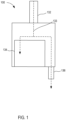
- the control device 100 includes an inlet 132 at least one outlet 136, and a sequestration and/or diversion portion 134 (also referred to herein as "sequestration portion").
- the control device 100 defines one or more fluid flow paths 133 between the inlet 132 and the sequestration portion 134 and/or between the inlet 132 and the outlet(s) 136.
- the inlet 132 of the control device 100 is configured to be placed in fluid communication with a bodily fluid source.
- the inlet 112 can be coupled to and/or can include an inlet device such as, for example, an intravenous (IV) catheter, a needle, a peripherally inserted central catheter (PICC), a syringe, a port, a coupler, one or more pieces of sterile tubing, and/or any other suitable lumen-containing device and/or intermediary transfer device.
- the inlet can be a port, a valve, and/or the like such as, for example, a Luer Lok ® or any other suitable coupler.
- the inlet 132 can be in fluid communication with the access or inlet device via an intermediate lumen-containing device such as, for example, sterile tubing or the like.
- the inlet 132 of the control device 100 can form and/or can be integrally or monolithically formed with the access or inlet device.
- the sequestration portion 134 can include one or more passive or active flow controllers (e.g., shapes, sizes, flow paths, materials configured to interact with fluid, actuators, plungers, pistons, valves, flow restrictors, seals, vents, etc.,) that can be actuated, engaged, manipulated, and/or controlled to urge, draw, direct, and/or divert fluid (e.g., bodily fluid, air or other gases, and/or the like) into or out of the sequestration portion 134.
- passive or active flow controllers e.g., shapes, sizes, flow paths, materials configured to interact with fluid, actuators, plungers, pistons, valves, flow restrictors, seals, vents, etc.
- the sequestration portion 134 can include any suitable arrangement, configuration, and/or feature, and/or can be formed of one or more materials configured to interact with a portion of the bodily fluid transferred into the sequestration portion 134.
- the control device 100 can include an absorbent and/or hydrophilic material disposed within the sequestration portion 134. Accordingly, when bodily fluid is transferred into the sequestration portion 134, the absorbent and/or hydrophilic material can absorb, attract, retain, expand, and/or otherwise interact with at least a portion of the bodily fluid, which in turn, can sequester and/or retain at least an initial portion of the bodily fluid within the sequestration portion 134, as described in further detail herein.
- the sequestration portion 134 can include structures or substances that are activated or deactivated to move or aid in the movement of the actuators from an initial state to a resulting state.
- the structures or substances can be activated by any suitable mechanism, for example, by contact with a small amount of bodily fluid (or any other fluid), by the passage of predetermined amount of time, by changes in pressure or temperature, by expansion or contraction of a volume, and/or the like.
- the initial state can be one in which the flow controller(s) or a portion thereof has a high potential energy and an activation of the flow controller results in conversion of the potential energy to kinetic energy.
- activation of substances can be the reconstitution of dried chemicals producing gaseous substances that move the plungers.
- the opening and/or the semi-permeable member can be configured to "vent" the sequestration portion 134.
- the venting of the sequestration portion 134 as an initial portion of the bodily fluid is transferred into the sequestration portion 134 can allow for an equalization of pressure in the sequestration portion 134 and/or between the sequestration portion 134 and, for example, the fluid source and/or a portion of the fluid flow path outside of the sequestration portion 134, or a pressure of an ambient environment into which the sequestration portion 134 is vented.
- the equalization of pressure can be a factor in determining and/or defining how bodily fluid flows through the control device 100 and/or the amount or volume of bodily fluid to be transferred into the sequestration portion 134.
- the fluid collection device can include a vacuum seal that maintains negative pressure conditions (vacuum conditions) inside the fluid collection device, which in turn, can facilitate withdrawal of bodily fluid from the patient, through the control device 100, and into the fluid collection device, via a vacuum or suction force.
- the fluid collection device is an evacuated container or the like
- the user can couple the fluid collection device to the outlet 136 after the initial portion of the bodily fluid is transferred into and/or sequestered by the sequestration portion 134, which in turn, can limit and/or substantially prevent an initial portion of the bodily fluid (potentially containing contaminants) from being transferred into the fluid collection device, as described in further detail herein.
- control device 100 can be used in conjunction with any suitable bodily fluid collection device and/or system.
- control device 100 described herein can be used in any suitable fluid transfer device such as those described in U.S. Patent Publication No. 2015/0342510 entitled, “Sterile Bodily-Fluid Collection Device and Methods," filed June 2, 2015 (referred to herein as the "510 publication"), the disclosure of which is incorporated herein by reference in its entirety and attached hereto as Exhibit B.
- the outlet 136 can be fluidically coupled to the fluid collection device.
- the fluid collection device can be any suitable reservoir, container, and/or device configured to receive a volume of bodily fluid.
- the fluid collection device can be an evacuated reservoir or container that defines a negative pressure and/or can be a syringe that can be manipulated to produce a negative pressure.
- control device 100 can be configured to transfer a volume of bodily fluid (e.g., the initial volume) into the sequestration portion 134 until a pressure differential between the sequestration portion 134 and the fluid flow path 133 and/or the bodily fluid source is brought into substantial equilibrium, substantial equalization, and/or is otherwise reduced below a desired threshold.
- a flow controller such as, for example, one or more mechanical actuators (e.g., a plunger)
- an amount of movement and/or travel of the mechanical actuator can determine the resultant volume and/or pressure (or changes thereof) of or in the sequestration portion 134.
- the user can actuate an actuator or the like (not shown in FIG. 1 ) to transition the control device 100 from the first state to the second state.
- at least a portion of the initial volume of bodily fluid can transition the control device 100 from the first state to the second state.
- the control device 100 can include a bodily fluid activated flow controller such as a switch, valve, port, and/or the like.
- a volume of bodily fluid can move and/or displace one or more flow controllers such as actuators or the like that can, for example, open a port, flow path, and/or outlet.
- a user can manipulate a flow controller such as a switch, valve, port, actuator, etc. to transition the control device 100 from the first state to the second state.
- the fluid collection device (not shown in FIG. 1 ) can be at least fluidically coupled to the outlet 136 before or after the control device 100 is placed in the second state.
- the arrangement of the outlet 136 can be such that the outlet 136 (or portion of the fluid flow path 133 leading to the outlet 136) remains sealed until the initial volume of bodily fluid is sequestered in the sequestration portion 134 regardless of whether the fluid collection device is coupled to the outlet 136.
- any subsequent volume(s) of the bodily fluid can flow from the inlet 132, through the fluid flow path 133 and the outlet 136, and into the fluid collection device.
- sequestering the initial volume of bodily fluid in the sequestration portion 134 prior to collecting or procuring one or more sample volumes of bodily fluid reduces and/or substantially eliminates an amount of contaminants in the one or more sample volumes.
- the arrangement of the control device 100 can be such that control device 100 cannot transition to the second state prior to collecting and sequestering the initial volume in the sequestration portion 134.
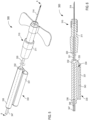
- FIGS. 2-4 illustrate a fluid control device 200 according to an embodiment.
- the fluid control device 200 (also referred to herein as “control device” or “device”) is configured to withdraw and sequester a first portion or amount (e.g., an initial amount) of bodily fluid from a patient or other bodily fluid source, and subsequently withdraw a second portion or amount (e.g., a subsequent amount) of bodily fluid for use, for example, in bodily fluid sampling and/or testing.
- a first portion or amount e.g., an initial amount
- a second portion or amount e.g., a subsequent amount
- portions and/or aspects of the control device 200 are substantially similar in form and/or function to the corresponding portions and/or aspects of the control device 100 described above with reference to FIG. 1 . Accordingly, such similar portions and/or aspects are not described in further detail herein.
- the housing 230 of the control device 200 can be any suitable device or set of devices configured to (1) receive a flow of bodily fluid, (2) store and sequester, segregate, retain, contain, isolate, etc., a first volume or initial volume of the bodily fluid, and (3) direct or divert a subsequent flow of the bodily fluid to a fluid collection device, as described in further detail herein.
- the sequestration portion 234 can include and/or can house one or more flow controllers or the like configured to interact with the bodily fluid transferred into the sequestration portion 234.
- the sequestration portion 234 can include one or more materials configured to interact with the bodily fluid.
- the one or more materials can be any suitable configuration such as the configuration described above with reference to the sequestration portion 134.
- the housing 230 includes a hydrophilic material 240 (e.g., foam, sintered plastic, bodily-fluid-absorbing material, and/or the like) and a vent material 242 (e.g., a selectively permeable material) disposed within the sequestration portion 234.
- the vent material 242 can be configured to vent the sequestration portion 234 via the opening 235 to allow, enhance, facilitate, and/or otherwise urge the flow of bodily fluid into the sequestration portion 234.
- the arrangement of the vent material 242 can be such that the bodily fluid wets the vent material 242 as the bodily fluid is transferred into the sequestration portion 234.
- the vent material 242 can swell and/or can otherwise can transition from a configuration and/or state in which the vent material 242 vents the sequestration portion 234 to a configuration and/or state in which the vent material 242 seals the sequestration portion 234. That is to say, the vent material 242 can be a self-sealing material configured to selectively allow a flow of gas (e.g., air) to vent from the sequestration portion 234 through the opening 235.
- a flow of gas e.g., air
- the device 200 can be used to divert, sequester, isolate, retain (e.g., passively divert) etc., a first or initial volume of bodily fluid such that subsequently procured or transferred bodily fluid samples have reduced contamination from microbes such as, for example, dermally residing microbes or microbes residing on incompletely sterilized transfer apparatus and/or the like.
- a user such as a doctor, physician, nurse, phlebotomist, technician, etc.
- the inlet device 310 is not described in further detail herein. As described above with reference to the inlet device 210 of the control device 200, while illustrated as a needle for procuring fluids directly from a patient (e.g., from a vasculature of the patient) in FIGS. 5-6 , the inlet device 310 can in other embodiments be configured to obtain fluid from a reservoir or container or the like of bodily fluid collected from a patient.
- the inlet device in some instances can include suitable ports or couplers or the like that can be connected to corresponding ports or couplers or the like of a reservoir containing collected bodily fluid or to corresponding ports or couplers of transfer apparatus that may in turn be connected a collected source of bodily fluid.
- the inlet device to couple with a transfer apparatus or a reservoir of collected fluid can include associated structures and/or control devices to operate the inlet device to control the fluidic communication between the inlet device and the source of bodily fluid.
- the sequestration portion 334 and more specifically, an inner volume of the expandable bladder 343 disposed therein is at least temporarily placed in fluid communication with the inlet 332 via the fluid flow path 333 and is configured to (1) receive a flow and/or volume of bodily fluid from the inlet 332 and (2) sequester (e.g., separate, segregate, contain, retain, isolate, etc.) the flow and/or volume of bodily fluid therein.
- sequester e.g., separate, segregate, contain, retain, isolate, etc.
- the sequestration portion 334 can be configured to vent a volume of the sequestration portion 334 that is outside of and/or surrounding the expandable bladder 343 as the flow and/or volume of bodily fluid is transferred into the expandable bladder 343, which in turn, can displace air or gas that otherwise may resist and/or limit expansion of the expandable bladder 343.
- the sequestration portion 334 can include and/or can define a vent that can allow a flow of air or gas to be vented from a volume of the sequestration portion 334 that is outside of and/or that surrounds the expandable bladder 343 as the volume of the expandable bladder 343 is increased.
- the outlet 336 and/or a portion of the fluid flow path 333 leading to the outlet 336 is not vented and/or otherwise sealed and as such, the venting of the volume of the sequestration chamber 334 outside of the expandable bladder 343 can facilitate and/or draw the flow of bodily fluid into the expandable bladder 343.
- the expandable bladder 343 can include and/or can house an expandable material such as a foam or sintered plastic, which can absorb, attract, urge, draw, retain, expand, and/or otherwise interact with at least a portion of the bodily fluid. Moreover, as the material expands in response to being wetted by the bodily fluid, the expandable bladder 343 likewise expands allowing the bodily fluid to flow therein.
- an expandable material such as a foam or sintered plastic
- bodily fluid can flow from the bodily fluid source (e.g., the vein of the patient, or the collected fluid source), through the inlet device 310, and into the housing 330.
- the bodily fluid source e.g., the vein of the patient, or the collected fluid source
- the outlet 336 is in fluid communication with one or more fluid collection devices (e.g., via the flexible outlet tubing 347) such that the subsequent volume(s) of the bodily fluid can flow from the inlet 332, through the fluid flow path 333, the outlet 336, and the flexible outlet tubing 347, and into the fluid collection device (not shown).
- one or more fluid collection devices e.g., via the flexible outlet tubing 347
- sequestering the initial volume of bodily fluid in the sequestration portion 334 prior to collecting or procuring one or more sample volumes of bodily fluid reduces and/or substantially eliminates an amount of contaminants in the one or more sample volumes.
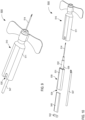
- the control device 400 includes an inlet device 410 and a housing 430 in fluid communication with and/or configured to be placed in fluid communication with the inlet device 410.
- the inlet device 410 can be any suitable device(s) such as, for example, an IV catheter, a sharpened catheter or sharpened needle, a port, a coupler, a connector, and/or any other suitable lumen-containing device.
- the inlet device 410 is a butterfly needle or other suitable access device having a body 411, a needle 414, and a flexible tubing 420.
- the inlet device 410 is similar to and/or substantially the same as the inlet device 210 described in detail above with reference to FIGS.
- the housing 430 can be similar in at least form or function to the housing 230 and/or 330 described in detail above with reference to FIGS. 2-4 and 5-6 , respectively. Thus, portions and/or aspects of the housing 430 are not described in further detail herein.
- the housing 430 can differ from the portions 230 and 330, however, in the arrangement of the sequestration portion 434.
- the sequestration portion 234 and the outlet 236 of the housing 230 were offset and/or non-coaxial from the inlet 232 thereof, in the embodiment shown in FIGS. 7 and 8 , the sequestration portion 434 is "in-line" or coaxial with the inlet 432 and the outlet 436.
- bodily fluid can flow within the fluid flow path 433 of the housing 430 from the inlet 432 to or through the sequestration portion 434 and then can flow within the fluid flow path 433 from the sequestration portion 434 to the outlet 436.
- the sequestration portion 434 includes a flow controller or the like such as, for example, a hydrophilic material 440 disposed therein.
- the hydrophilic material 440 can be substantially similar to and/or the same as the hydrophilic material 240 described above with reference to FIGS. 2-4 .
- the hydrophilic material 440 can be any suitable material and/or flow controller configured to attract, collect, and/or absorb fluid.
- the hydrophilic material 440 can include and/or can define a lumen 441 extending through the material 440. For example, as shown in FIG.
- the arrangement of the sequestration portion 434 and the hydrophilic material 440 is such that the hydrophilic material 440 absorbs, retains, and/or sequesters the initial volume or amount of bodily fluid.
- contaminants such as, for example, dermally residing microbes or the like dislodged during the venipuncture event (and/or other undesirable microbes), can be entrained and/or included in the initial volume of the bodily fluid and thus, can also be sequestered in or by the hydrophilic material 440 in the sequestration portion 434.
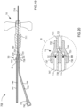
- a proximal end portion of the needle 514 extends through the inlet 532 to place a lumen 515 defined by the needle 514 in fluid communication with the fluid flow path 533 defined by the housing 530.
- the outlet 536 is physically and fluidically coupled to a flexible outlet tubing 547 (also referred to herein as "outlet tubing") configured to place the outlet in fluid communication with a fluid collection device (not shown).
- the outlet 536 is at least partially disposed within a slot 513 defined by the body 511 of the inlet device 510. Accordingly, the outlet 536 can coupled to the outlet tubing 547 without having to increase a size of the body 511 of the inlet device 510.
- the arrangement of the outlet 536 and/or a portion of the outlet tubing 547 extending through the slot 513 can allow the housing 530 to move within the body 511 of the inlet device 510.
- the device 500 can be configured such that the housing 530 can be moved relative to the inlet device 511 to selectively position the needle 514 relative to the inlet device 510.
- a portion of the body 531 of the housing 530 includes and/or defines the sequestration portion 534. More specifically, the body 531 of the housing 530 can include and/or can define the sequestration portion 534 at or in a portion that is proximal to the needle 514 and the outlet 536, as described in further detail herein. As described above with reference to the sequestration portion 234 of the housing 230, the housing 530 and/or the sequestration portion 534 includes and/or defines an opening 535 (e.g., a vent opening) in fluid communication with the sequestration portion 534 and/or otherwise has a proximal end that is substantially open.
- an opening 535 e.g., a vent opening
- the sequestration portion 534 includes and/or houses one or more flow controllers configured to interact with the bodily fluid transferred into the sequestration portion 534.
- the housing 530 includes a hydrophilic material 540 and a vent material 542 (e.g., one or more flow controller), which can be similar to and/or substantially the same as the hydrophilic material 240 and the vent material 242, respectively, of the housing 230.
- the vent material 542 can be configured to vent the sequestration portion 534 to allow, enhance, facilitate, and/or otherwise urge the flow of bodily fluid into the sequestration portion 534.
- the arrangement of the vent material 542 can be such that the bodily fluid wets the vent material 542 as the bodily fluid is transferred into the sequestration portion 534 and once sufficiently wetted and/or saturated, the vent material 542 can transition from a configuration and/or state in which the vent material 542 vents the sequestration portion 534 to a configuration and/or state in which the vent material 542 seals the sequestration portion 534, as described above with reference to the vent material 242.
- the device 500 shown in FIGS. 9-12 can be used to divert (e.g., passively) a first or initial volume of bodily fluid such that subsequently procured bodily fluid samples have reduced contamination from microbes such as, for example, dermally residing microbes or microbes residing on incompletely sterilized transfer apparatus and/or the like.
- a user such as a doctor, physician, nurse, phlebotomist, technician, etc.
- a subsequent flow and/or volume of bodily fluid can enter the fluid flow path 533 and the housing 530 can direct and/or divert the flow through a portion of the fluid flow path 533 and into the outlet 536.
- the outlet 536 is in fluid communication with one or more fluid collection devices (e.g., via the outlet tubing 547) such that the subsequent volume(s) of the bodily fluid can flow from the outlet 536 and the outlet tubing 547, and into the fluid collection device (not shown).
- a proximal end portion of the needle 614 extends through the inlet 632 to place a lumen 635 defined by the needle 614 in fluid communication with the fluid flow path 633 defined by the housing 630.
- the outlet 636 is physically and fluidically coupled to a flexible outlet tubing 647 (also referred to herein as "outlet tubing") configured to place the outlet in fluid communication with a fluid collection device (not shown).
- a fluid collection device not shown.
- the outlet 636 is at least partially disposed within a slot 613 defined by the body 611 of the inlet device 610. In some embodiments, such an arrangement can allow for movement of the housing 630 relative to the inlet device 610, as described in detail above with reference to the device 500.
- the housing 630 can differ from the housing 530, however, by including a movable seal 644 configured to form a boundary and/or surface of the sequestration portion 634.
- the movable seal 644 includes and/or forms a sleeve 645 and an extension 646 extending from the sleeve 645.
- the seal 644 is movably disposed in the inner volume of the body 631 and is in contact with an inner surface of the body 631 that defines at least a portion of the sequestration portion 634. More specifically, as shown in FIGS.
- the extension 646 of the seal 644 is configured to selectively obstruct the outlet 636 of the housing 630.
- the extension 646 can contact a portion of the inner surface of the body 631 to form and/or define a fluidic seal therebetween.
- the movable seal 644 when the movable seal 644 is in a distal position (e.g., a first or initial position, state, and/or configuration), the extension 646 obstructs the outlet 636 and sequesters or isolates the outlet 636 from the fluid flow path 633.
- contaminants such as, for example, dermally residing microbes or the like dislodged during the venipuncture event, can be entrained and/or included in the initial volume of the bodily fluid and thus, can also be sequestered in the sequestration portion 634 when the initial volume is sequestered therein.
- the movement of the seal 644 in the AA direction moves the extension 646 of the seal 644 relative to the outlet 636.
- movement of the seal 644 in response to the first or initial volume being transferred into the sequestration portion 634 and/or being absorbed by the hydrophilic material 640 places the extension 646 in a proximal position relative to the outlet 636.
- fluid communication is established between the outlet 636 and the fluid flow path 633, which in turn, is operable to transition the device 600 from the first state to the second state in which a subsequent volume(s) of bodily fluid can flow through at least a portion the fluid flow path 633 and through the outlet 636.
- the lumen 739 can form, for example, a sequestration and/or diversion portion and/or the like, as described in further detail herein.
- the second outlet is in fluid communication with a second flexible outlet tubing 747 (also referred to herein as "second outlet tubing"), which defines a lumen 748 configured to place the second outlet 747 in fluid communication with one or more fluid collection devices (not shown).
- a portion of the fluid flow path 733 associated with and/or defined by the second outlet 737 can be offset and/or misaligned from the portion of the fluid flow path 733 associated with and/or defined by the inlet 732, which in turn, forms and/or defines a reduced diameter and/or other suitable restriction therebetween.
- the restrictions or the like can allow for selective fluid flow from the inlet 732 to the first outlet 736 or the second outlet 737 based on, for example, a magnitude of a pressure differential and/or the like, as described in further detail herein.
- the first or initial amount of bodily fluid is a volume sufficient to wet or saturate the vent material 742.
- the vent material 742 e.g., flow controller
- the vent material 742 can be configured to transition from an open or venting state or configuration to a closed or sealed configuration in response to being wetted or saturated (e.g., fully saturated).
- fully filling the lumen 739 of the first outlet tubing 738 and/or saturating the vent material 742 can place the housing 730 and/or the device 700 in a second state or configuration, in which any subsequent volume of bodily fluid flows through the fluid flow path 733 and into the second outlet 737, as indicated by the arrow CC in FIG. 20 .
- portions and/or aspects of the control device 800 are substantially similar in form and/or function to the corresponding portions and/or aspects of the control device 100 described above with reference to FIG. 1 . Accordingly, such similar portions and/or aspects are not described in further detail herein.
- the control device 800 can be any suitable shape, size, and/or configuration.
- the control device 800 can have a size that is at least partially based on a volume of bodily fluid at least temporarily stored, for example, in the sequestration portion 834.
- the control device 800 can include and/or can form a bifurcation (e.g., a Y-shaped or T-shaped bifurcation, or the like) forming one or more portions of the fluid flow path 833.
- the control device 800 can be formed of a relatively rigid material such as rigid plastic or the like and can be configured to retain its shape and/or form when exposed to changes in pressure and/or inlet and outlet flows of fluid.
- some portions of the control device 800 can be formed of a relatively rigid material while some other portions of the control device 800 (e.g., tubing or the like defining at least a portion of the flow path(s) 833) can be formed of relatively flexible material such as flexible plastic, rubber, or the like.
- the inlet 832 (or inlet portion) can include and/or can define a first portion of the flow path 833
- the sequestration portion 834 (or a portion of the sequestration portion 834) can include and/or can form a second portion of the flow path 833
- the outlet 836 (or outlet portion) can include and/or can define a third portion of the flow path 833.
- the inlet 832 (or inlet portion), the sequestration portion 834 (or portion thereof), and the outlet 836 (or outlet portion) can include and/or can be formed with or by one or more tubes or other lumen-containing devices, coupled to each other through one or more suitable couplers or ports (e.g., a T-connector, Y-connector, and/or any other suitable coupler(s)) or attached to each other through any suitable mechanism to form portions of a continuous fluid flow path 833.
- suitable couplers or ports e.g., a T-connector, Y-connector, and/or any other suitable coupler(s)
- control device 800 (and/or the inlet 832, the sequestration portion 834, the outlet 836, and/or the junction 817) can be arranged such that any suitable portion of the flow path 833 has any suitable and/or desired length, width, shape, and/or configuration.
- any suitable portion(s) of the flow path 833 can have any suitable form and/or can include any suitable inner surface (e.g., a textured inner surface, a grooved inner surface, a smooth inner surface, etc.).
- the sequestration portion 834 of the control device 800 includes a hydrophilic material 840 (e.g., foam, sintered plastic, bodily-fluid-absorbent material, and/or the like) disposed within the sequestration portion 834.
- the sequestration portion 834 also includes a vent material 842 (e.g., semi-permeable membrane or material, etc.) disposed within the opening 835.
- the space 845 can include, for example, a volume of air or other gaseous contents that can be vented through the opening 835 prior to drawing in bodily fluid to be sequestered.
- the space 845 can be configured to at least accommodate any expansion of the hydrophilic material 840 upon absorption of the initial volume of bodily fluid.
- the space 845 can be configured to facilitate and/or otherwise allow expansion of the hydrophilic material 840, which in turn, can result in a pressure differential that draws or helps draw a flow of bodily fluid towards and into the sequestration portion 834.
- the hydrophilic material 840 and the vent material 842 can be coupled during manufacturing and/or otherwise co-formed or unitarily formed. Accordingly, the hydrophilic material 840 and the vent material 842 each can be a flow controller or can collectively be a flow controller configured to selectively control a flow of fluid (e.g., gas and/or liquid) into and out of the sequestration portion 834.
- a flow of fluid e.g., gas and/or liquid
- the outlet 836 formed by and/or included in the control device 800 is at least fluidically coupled to the junction 817 and/or is otherwise in coupled to the control device 800 such that the outlet 836 is in fluid communication with the flow path 833.
- the outlet 836 can be physically and fluidically coupled to the junction 817 and/or otherwise can be an integrally formed portion of the control device 800.
- the control device 800, the junction 817, and/or the outlet 836 (or outlet portion) can include a sterile flexible tubing or the like configured to place the outlet 836 in fluid communication with the junction 817 and thus, in fluid communication with and/or defining at least a portion of the flow path 833.
- the outlet 836 can be in fluid communication with and/or coupled to, for example, the junction 817 via one or more pieces of tubing, which can be joined together to form a continuous lumen.
- the outlet 836 can be any suitable outlet, opening, port, lock, seal, coupler, etc. and is in fluid communication with at least a portion of the fluid flow path 833.
- the outlet 836 can be a port, coupler, transfer adapter, and/or device that is coupled to control device 800 (e.g., via a flexible outlet tubing or the like) via any suitable connection, fit, adhesive, etc.
- the outlet 836 can include and/or can be coupled to an outlet needle or the like.
- the outlet 836 can be coupled to a transfer adapter and/or the like such as, for example, the transfer adapters described in the '352 publication.
- the device 800 can be used to divert (e.g., passively divert) and/or otherwise facilitate a flow of a first or initial volume of bodily fluid such that subsequently procured bodily fluid samples have reduced contamination from microbes such as, for example, dermally residing microbes and/or the like.
- a user such as a doctor, physician, nurse, phlebotomist, technician, etc.
- the device 800 can manipulate the device 800 by inserting at least a portion of an inlet device such as, for example, a needle, into a patient's vein (e.g., a venipuncture event) and/or can otherwise establish fluid communication between the needle and the patient.
- an inlet device such as, for example, a needle
- bodily fluid can flow from the bodily fluid source (e.g., the vein of the patient), through the inlet 832 and into the control device 800.
- the control device 800 can be in and/or can be placed in a first or initial state in which an initial portion or volume of bodily fluid can flow in or through at least a portion the fluid flow path 833 and into the sequestration portion 834.
- the device 800 can transition to the second state in which a subsequent volume(s) of bodily fluid can flow through at least a portion the fluid flow path 833 from the inlet 832, through the junction 817, and to the outlet 836.
- the control device 800 is configured to automatically transition (e.g., without user intervention) from the first state to the second state once the initial volume of bodily fluid is sequestered in the sequestration portion 834.
- filling the sequestration portion 834 to capacity and/or saturating, wetting, and/or impregnating the hydrophilic material 840 and/or the vent material 842 can limit and/or substantially prevent any additional volume of bodily fluid from being transferred into the sequestration portion 834.
- saturating, wetting, and/or impregnating the hydrophilic material 840 and/or the vent material 842 can limit and/or substantially prevent any fluid flow out of the sequestration portion 834 and back into the fluid flow path 833.
- the transitioning of the control device 800 can be at the junction 817 and/or can be a result of the junction 817 transitioning from a first state to a second state.
- the outlet 936 can be similar to or substantially the same as the outlets 136, 236, 336, 436, 536, 636, 736, and/or 836.
- the fluid collection device configured to be coupled to the outlet 936 can be similar to or substantially the same as any of the fluid collection devices described above. Accordingly, the outlet 936 and the fluid collection device coupled to the outlet 936 are not described in further detail herein.
- the control device 900 defines one or more fluid flow paths 933 between the inlet 932 and the sequestration portion 934 and/or between the inlet 932 and the outlet(s) 936.
- the control device 900 can be configured such that a first portion of the fluid flow path 933 (also referred to herein as "flow path") places the inlet 932 in selective fluid communication with the sequestration portion 934, and a second portion of the flow path 933 places the inlet 932 in selective fluid communication with the outlet 936.
- the control device 900 can include a junction 917 or the like collectively formed at or near a connection of the inlet 932 (or inlet portion), the sequestration portion 934 (or portion thereof), and the outlet 936 (or outlet portion).
- the control device 900 can be configured to transition at or near the junction 917 to control a flow of bodily fluid therethrough, as described above with reference to the control device 800.
- the control device 900 can be similar in at least form or function to the control device 800 described in detail above with reference to FIGS. 21 and 22 , except for the differences described below, and thus, such similar portions and/or aspects of the control device 900 are not described in further detail herein.
- the control device 900 can differ from the control device 800, for example, in the arrangement and/or shape of the sequestration portion 934.
- the sequestration portion 834 of the control device 800 has a relatively shallow cylindrical shape
- the sequestration portion 934 in the control device 900 can have and/or can assume a fan-like shape, as indicated by side view illustration in FIG. 23 and the cross-sectional view in FIG. 24 .
- the sequestration portion 934 can include a hydrophilic material 940 (e.g., flow controller) disposed therein, and the hydrophilic material 940 can conform to any suitable shape (e.g., the shape of the sequestration portion 934), as described below.
- the hydrophilic material 940 can have any suitable geometry, size, and/or configuration. For example, as shown in the embodiment illustrated in FIGS. 23 and 24 , the hydrophilic material 940 assumes a shape that matches the shape and geometry of the sequestration portion 934. That is, in this embodiment, the hydrophilic material 940 assumes a two-layered fan shape defining a space or gap 945 between the two layers of hydrophilic material 940 to allow fluid flow from the fluid flow path 933 into the sequestration portion 934.
- the fan-shaped form of the hydrophilic material 940 can be configured to facilitate a substantially free flow of the bodily fluid drawn into the sequestration portion 934 without clogging, and the gap or space 945 can allow for an expansion of the hydrophilic material 940, which in turn, can aid in establishing a negative pressure differential between the sequestration portion 934 and at least a portion of the fluid flow path 933, thereby enhancing the drawing, wicking, or pumping action of the hydrophilic material 940 disposed in the sequestration portion 934.
- the expansion of the hydrophilic material 940 in the two-layered, fan-shaped form increases the volume of the hydrophilic material 940, which in turn, draws in bodily fluid (e.g., via capillary action, wicking, absorption, etc.).
- the specific shape of the sequestration portion 934 and the hydrophilic material 940 can be configured to result in a desired and/or predetermined flow of bodily fluid into the sequestration portion 934.
- the fan-shaped form of the sequestration portion 934 and the hydrophilic material 940 in the embodiment illustrated in FIGS.
- the space 945 defined by the hydrophilic material 940 can form a channel to allow fluid flow into the sequestration portion 934, without clogging, clumping, or other sources of disruption of the drawing, wicking, and/or pumping action associated with the expansion of the hydrophilic material 940.
- the sequestration portion 934 can also define an opening 935 and can include a vent material 942 (e.g., flow controller) disposed within the opening 935. Similar to the description above with reference to the vent material 842 disposed in the opening 835 of the control device 800, the vent material 942 can be configured to vent the sequestration portion 934 through the opening 935.
- the opening 935 and/or the vent material 942 can be configured to transition from an open or venting configuration and/or state prior to the sequestration portion 934 receiving a first or initial volume of bodily fluid, to a sealed, closed, and/or otherwise not vented configuration, after the first or initial volume of bodily fluid has flowed into the sequestration portion 934.
- the arrangement of the hydrophilic material 940 can be such that the opening 935 need not include the vent material 942 and/or any other selectively permeable member or membrane to prevent the venting or escaping of bodily fluid (e.g., a portion of the hydrophilic material 940 is disposed in or about the opening 935 and functions similarly to the vent material 942).
- the hydrophilic material 940 and the vent material 942 each can be a flow controller or can collectively be a flow controller configured to selectively control a flow of fluid (e.g., gas and/or liquid) into and out of the sequestration portion 934.
- the device 900 shown in FIGS. 23 and 24 can be used to divert (e.g., passively) a first or initial volume of bodily fluid such that subsequently procured bodily fluid samples have reduced contamination from microbes such as, for example, dermally residing microbes and/or the like.
- the control device 900 can be in and/or can be placed in a first or initial state in which an initial portion or initial volume of bodily fluid can flow in or through at least a portion the fluid flow path 933, through at least a portion of the junction 917, and into the sequestration portion 934.
- transferring the initial portion or volume of bodily fluid into the sequestration portion 934 can place the hydrophilic material 940 (and/or any other suitable flow controller) in an expanded state and/or configuration and, as such, the hydrophilic material 940 can substantially prevent any subsequent volume of bodily fluid from being disposed in the sequestration portion 934.
- the central space or gap 945 defined by the hydrophilic material 940 operable to allow fluid flow into the sequestration portion 934 without clogging or otherwise disrupting the pump or wicking action of the hydrophilic material 940, can be reduced, shrunk, narrowed, and/or closed in. In some instances, closing of the space 945 can prevent any subsequent volume of bodily fluid from flowing into and/or out of the sequestration portion 934.
- the saturation of the hydrophilic material 940 and/or the saturation of the vent material 942 can occur concurrently and can collectively limit and/or substantially prevent a subsequent flow of fluid into and/or out of the sequestration portion 934.
- at least a portion of the junction 917 leading to the sequestration portion 934 can include a valve, a selectively permeable membrane, fluid activated (e.g., bodily fluid activated) switch or seal, user activated switch or seal, and/or the like that can limit and/or substantially prevent a flow of bodily fluid into and/or out of the sequestration portion 934.
- contaminants such as, for example, dermally residing microbes or the like dislodged during the venipuncture event, can be entrained and/or included in the initial volume of the bodily fluid and thus, can also be sequestered in the sequestration portion 934 when the initial volume is sequestered therein.
- a control device can include a sequestration and/or diversion portion that can include any suitable flow controller configured to draw bodily fluid into the sequestration chamber.
- FIG. 25 illustrates a fluid control device 1000 according to an embodiment.
- the control device 1000 includes and/or forms a junction 1017 or the like formed at or near a connection of the inlet 1032 (or inlet portion), the sequestration portion 1034 (or portion thereof), and the outlet 1036 (or outlet portion). Furthermore, the control device 1000 defines a fluid flow path 1033 (also referred to herein as "flow path") that places the inlet 1032 (or inlet portion) in selective fluid communication with the sequestration portion 1034 and/or the outlet 1036 (or outlet portion). As described in further detail herein, in some embodiments, the control device 1000 can be configured to transition at or near the junction 1017 to control bodily fluid flowing through the flow path 1033, as described above with reference to the control devices 800, and/or 900.
- the inlet 1032 formed by and/or included in the control device 1000 is configured to place the control device 1000 in fluid communication with a bodily fluid source (e.g., via an access or inlet device), as described in detail above.
- the outlet 936 formed by and/or included in the control device 900 is configured to be fluidically coupled to a fluid collection device (e.g., a syringe, evacuated container, dish, sampling device or machine, etc.).
- a fluid collection device e.g., a syringe, evacuated container, dish, sampling device or machine, etc.
- the outlet 1036 can be any suitable outlet, opening, port, lock, seal, coupler, etc., as described above with reference to the outlets 136, 236, 336, 436, 536, 636, 736, 836 and/or 936.
- the sequestration portion 1034 can include a series of capillary tubes 1050 (e.g., flow controller(s)) each of which has a high surface area to volume ratio operable to draw fluid flow through the capillary tube(s) 1050.
- Each of the capillary tubes 1050 can have a desired diameter and can extend a desired length across or within the sequestration portion 1034.
- the capillary tubes 1050 can occupy a desired portion in a desired location of the sequestration portion 1034 such that bodily fluid can from the inlet 1032 into the sequestration portion 1034 (e.g., the capillary tubes 1050 need not occupy all of the sequestration portion 1034).
- the number and shape of the capillary tubes 1050 can at least partially be designed to determine the volume of bodily fluid drawn into the sequestration portion 1034.
- the sequestration portion 1034 is described as including one or more capillary tubes 1050 operable to draw bodily fluid into the sequestration portion 1034 (e.g., via capillary action, wicking, etc.)
- a sequestration chamber can include any suitable material, structure, formation, feature, etc. configured to draw bodily fluid into the sequestration chamber via capillary action, wicking, and/or any other suitable mode.
- the vent material 1042 can be similar to or substantially the same as the vent material 842 and/or 942 included in the control devices 800 and/or 900, respectively. Accordingly, the vent material 1042 is not further described in detail here. In other embodiments, the arrangement of the capillary tubes 1050 can be such that the sequestration portion 1034 need not include the vent material or the like disposed in and/or about the opening.
- filling or substantially filling the sequestration portion 1034 can transition the vent material 1042 (e.g., flow controller) from a first state in which the vent material 1042 allows venting of the sequestration portion 1034 through the opening 1035 to a second state in which the vent material 1042 is saturated, sealed, and/or otherwise prevents a venting through the opening 1035, which in turn, can result in and/or can allow pressures to equalize.
- the vent material 1042 e.g., flow controller
- the device 1000 can transition to the second state in which a subsequent volume(s) of bodily fluid can flow through at least a portion the fluid flow path 1033 from the inlet 1032, through the junction 1017 and the outlet 1036, and into a fluid collection device fluidically coupled to the outlet 1036.
- the control device 1000 is configured to automatically transition (e.g., without user intervention) from the first state to the second state once the initial volume of bodily fluid is sequestered in the sequestration portion 1034.
- the control device 1100 can have any suitable size and/or shape.
- the control device 1100 illustrated in FIG. 25 forms a bifurcation (e.g., a Y-shaped bifurcation, T-shaped bifurcation, and/or the like). More specifically, the inlet 1132 or inlet portion, the outlet 1136 or outlet portion, and the sequestration portion 1134 or portion thereof are coupled, joined, and/or otherwise meet at the junction 1117.
- the junction 1117 is configured to selectively establish fluid communication between the inlet 1132 or inlet portion and the sequestration portion 1134 or portion thereof, and between the inlet 1132 or inlet portion and the outlet 1136 or outlet portion, as described in further detail herein. While the control device 1100 is shown in FIG. 26 as forming the Y-shaped bifurcation, in other embodiments, the control device 1100 can form any suitable shape and/or can have any suitable configuration or arrangement.
- the actuator 1151 is disposed within the sequestration portion 1134 such that movement of the actuator 1151 can define and/or can result in a change of the relative sizes of the first and second volumes of the sequestration portion 1134.
- the actuator 1151 can be in an initial state or position and can be held and/or retained in the initial state or position via one or more active or passive mechanisms and/or means.
- the actuator 1151 or a portion thereof can have a relatively high potential energy and/or can be disposed in a configuration associated with a relatively high potential energy.
- the actuator 1151 can be configured such that the activation of the actuator 1151 converts that potential energy into other suitable forms, for example, kinetic energy, etc.
- the actuator 1151 can be held in an initial state at rest and the activation can involve actively moving the actuator 1151 away from the initial resting state (e.g., as described below with reference to the embodiment illustrated in FIG. 27 ).
- the device 1100 in FIG. 26 can include a dissolvable bonding substance 1155 (e.g., glue, adhesive, fastener, epoxy, foam, and/or the like) that at least temporarily bonds the actuator 1151 to one or more surfaces of the sequestration portion 1134 until it is dissolved, for example, by contact with a flow of bodily fluid into the sequestration portion 1134.
- a dissolvable bonding substance 1155 e.g., glue, adhesive, fastener, epoxy, foam, and/or the like
- the actuator 1151 can be suitably configured in form, shape, size, surface, etc., to facilitate the temporary bonding of the actuator 1151 to the surface(s) or wall(s) of the sequestration portion 1134 using the bonding substance 1155.
- the actuator 1151 can include and/or can have a surface area and/or a surface finish that increases and/or facilitates adhesion.
- at least a portion of the actuator 1151 can be formed of a porous and/or absorbent material configured to increase and/or facilitate adhesion to and/or with the bonding substance 1155. In the embodiment shown in FIG.
- the venting through the opening 1159 can be similar to the venting described above with reference to the devices 100, 200, 300, 400, 500, 600, 700, 800, 900 and/or 1000.
- the sequestration portion 1134 does not include a vent material or the like disposed within the opening 1159 (as described above with reference to the other devices) because the arrangement of the actuator 1151 is such that the second volume of the sequestration portion 1134 is fluidically isolated from the first volume of the sequestration portion 1134.
- the second volume of the sequestration portion 1134 does not receive a volume of bodily fluid that a vent material would otherwise prevent from exiting the opening 1159.
- the sequestration portion 1134 can also define an opening or vent that is in fluid communication with, for example, the first volume of the sequestration portion 1134.
- the vent material can be substantially similar to the vent materials described herein and can be configured to vent the first volume of the sequestration portion 1134.
- the venting of the first volume of the sequestration portion 1134 can result in a pressure differential between the first volume of the sequestration portion 1134 and, for example, the junction 1117 that can result in a desired and/or predetermined flow of bodily fluid into the first volume of the sequestration portion 1134.
- the vent material can be transitioned from a first or selectively permeable state to a second or substantially impermeable state in response to being saturated and/or wetted by the initial flow of bodily fluid into the first volume of the sequestration portion 1134.
- the control device 100 can be configured such that a volume of bodily fluid sufficient to transition the vent material to the substantially impermeable state also can be sufficient to dissolve the bonding material 1155.
- the vent or the like can be formed in a wall or surface of the sequestration portion 1134.
- the vent or the like can be formed in, for example, a portion of the actuator 1151 such that air or gas in the first volume of the sequestration portion 1134 is displaced and/or vented into the second volume of the sequestration portion 1134, which in turn, is vented to the ambient environment via the opening 1159.
- the device 1100 shown in FIG. 26 can be used to direct or divert a first or initial volume of bodily fluid such that subsequently procured bodily fluid samples have reduced contamination from microbes such as, for example, dermally residing microbes and/or the like.
- a user such as a doctor, physician, nurse, phlebotomist, technician, etc. establishes, fluid communication between the device 1100 and the source of bodily fluid (e.g., as described in detail above with reference to previous embodiments)
- bodily fluid can flow from the bodily fluid source (e.g., the vein of the patient or other suitable bodily fluid source) and into the control device 1100.
- the bodily fluid source e.g., the vein of the patient or other suitable bodily fluid source
- the spring 1154 retracts, compresses, and/or otherwise releases the tension (e.g., by converting potential energy to kinetic energy) to be placed in a resting state, which in turn, transitions and/or moves the actuator 1151 connected to the spring 1154 to the second state and/or position.
- the movement of the actuator 1151 within the sequestration portion 1134 changes and/or redistributes the first volume and the second volume of the sequestration portion 1134. That is, for example, as illustrated in FIG. 26 , the movement of the actuator 1151 increases the first volume of the sequestration portion 1134 and decreases the second volume of the sequestration portion 1134. Moreover, the increase in the first volume is accompanied by and/or otherwise results in a reduction in pressure (e.g., a suction force) in the first volume of the sequestration portion 1134.
- a suction force e.g., a suction force
- the reduction in pressure can draw and/or can aid in drawing or urging flow of the initial volume of bodily fluid into the first volume of the sequestration portion 1134.
- the amount and/or the rate of a volume of bodily fluid drawn into the sequestration portion 1134 can be at least partially determined by the size of the first and second volumes of the sequestration portion 1134, one or more properties associated with the actuator 1151 (e.g., weight, mobility, inertial forces against its movement, friction forces, gravity, etc.), the rate of dissolution of the dissolvable bonding substance 1155, one or more properties of the spring 1154 (e.g., size, material, length, elasticity, allowable tension forces, spring rate, etc.), and/or the like.
- the actuator 1151 e.g., weight, mobility, inertial forces against its movement, friction forces, gravity, etc.
- the rate of dissolution of the dissolvable bonding substance 1155 e.g., one or more properties of the spring 1154 (e.g., size, material, length, elasticity, allowable tension forces, spring rate, etc.), and/or the like.
- the movement of the actuator 1151 and the decrease in the second volume of the sequestration portion 1134 can result in the venting of the contents (e.g., air or gas) of the second volume of the sequestration portion 1134, by expulsion or release of the contents through the opening 1159.
- contents e.g., air or gas
- a size and/or configuration of the opening 1159 can be varied, for example, to control and/or modify one or more characteristics associated with the venting of the second volume of the sequestration portion 1134.
- the opening 1159 can have a relatively small diameter configured to limit flow through the opening 1159 and/or a material configured to limit flow can be disposed in the opening 1159.
- the limiting and/or restricting of flow (e.g., air or gas flow) through the opening 1159 can reduce a rate at which the second volume of the sequestration portion 1134 is vented, which in turn, can slow and/or modulate a rate at which the actuator 1151 is moved with the sequestration portion 1134.
- controlling the rate at which the actuator 1151 is moved within the sequestration chamber 1134 can, for example, modulate and/or control an amount of negative pressure within the first volume of the sequestration portion 1134.
- the opening 1159 can be sealed by the actuator 1151, preventing any leak or flow of bodily fluid through the opening 1159.
- the initial volume of bodily fluid is transferred and/or diverted into the sequestration portion 1134 and/or (any other suitable portion of the device 1100), the initial volume is sequestered, segregated, retained, contained, isolated, etc. in the sequestration portion 1134.
- transferring the initial portion or volume of bodily fluid into the resulting first volume of the sequestration portion 1134 can place the sequestration portion 1134 in a filled configuration and, as such, the volume of bodily fluid contained in the first portion of the sequestration portion 1134 substantially prevents any subsequent volume of bodily fluid from being disposed therein.
- filling or substantially filling the first volume of the sequestration portion 1134 can reduce and/or can substantially equalize a pressure differential generated between the sequestration portion 1134 and the junction 1117, for example, and/or portion of the flow path 1133 that is in fluid communication with the inlet 1132.
- the decrease in and/or the substantial equalization of the pressure differential can be such that the flow of any subsequent volume of fluid into the sequestration portion 1134 is limited and/or stops or substantially stops.
- the junction 1117 and/or portion of the sequestration portion 1134 can include a valve, a selectively permeable membrane, fluid activated (e.g., bodily fluid activated) switch or seal, user activated switch or seal, and/or the like that can limit and/or substantially prevent a flow of bodily fluid into or out of the sequestration portion 1134.
- fluid activated e.g., bodily fluid activated
- user activated switch or seal e.g., user activated switch or seal
- the like can limit and/or substantially prevent a flow of bodily fluid into or out of the sequestration portion 1134.
- contaminants such as, for example, dermally residing microbes or the like dislodged during the venipuncture event, can be entrained and/or included in the initial volume of the bodily fluid and thus, can also be sequestered in the sequestration portion 1134 when the initial volume is sequestered therein.
- the control device 1200 includes an inlet 1232 (or inlet portion), an outlet 1236 (or outlet portion), and a junction 1217, and includes and/or defines one or more fluid flow paths 1233 and a sequestration and/or diversion portion 1234 (also referred to herein as "sequestration portion").
- the inlet 1232 is configured to be placed in fluid communication with a bodily fluid source (either directly or indirectly), as described in detail above.
- the outlet 1236 is configured to be coupled to a fluid collection device (not shown), as described in detail above. Accordingly, the inlet 1232 and outlet 1236 are not described in further detail herein.
- the device 1200 illustrated in FIG. 27 includes a first channel 1218 and second channel 1258 forming one or more junctions with or along a portion of the device 1200.
- the first channel 1218 is in fluid communication with a first volume of the sequestration portion 1234 and is configured to place the sequestration portion 1234 in selective fluid communication with the junction 1217.
- the second channel 1258 is in fluid communication with a second volume of the sequestration portion 1234 and is configured to selectively place the second volume of the sequestration portion 1234 in fluid communication with a portion of the flow path 1233.
- the device 1200 and/or one or more portions thereof can include one or more valves or seals to selectively control a flow of fluid in one or more directions.
- the device 1200 includes a valve 1257 disposed between and/or otherwise configured to control a flow of fluid between a portion of the junction 1217 and the first channel 1218.
- the valve 1257 is configured to permit a flow of fluid from the junction 1217 and limit and/or substantially prevent a flow of fluid out of the first channel 1218.
- the valve 1257 can be any suitable valve such as, for example, a duckbill valve, a butterfly valve, a one-way check valve, etc. and can be made from any suitable material, with any size, shape, and/or other attributes, and configured with any suitable property.
- the sequestration portion 1234 can be configured to include one or more flow controllers configured to selectively control a flow of fluid into and/or out of the sequestration portion 1234.
- the one or more flow controllers can include, for example, actuators, plungers, pistons, seals, vents, selectively permeable materials, and/or the like that are disposed in the sequestration portion 1234 and configured to transition between one or more states, configurations, positions, and/or the like.
- the sequestration portion 1234 illustrated in FIG. 27 includes two actuators or plungers 1251 and 1253 (e.g., flow controllers), connected to each other through a connecting component 1252.
- the actuators 1251 and 1253 are in contact with an inner surface of the sequestration portion 1234 such that a substantially fluid tight seal is formed between the actuators 1251 and 1253 and a portion of the inner surface.
- the arrangement of the actuators 1251 and 1253 within the sequestration portion 1234 separates and/or otherwise defines three volumes of the sequestration portion 1234.
- the first volume of the sequestration portion 1234 is in fluid communication with the first channel 1218 and a portion of the sequestration portion 1234 defined between the valve 1257 and the first actuator 1251.
- the second volume of the sequestration portion 1234 is defined between the first actuator 1251 and the second actuator 1253 and is in fluid communication with the second channel 1258.
- the third volume of the sequestration portion 1234 is defined on a side of the second actuator 1253 opposite the second volume of the sequestration portion 1234.
- the sequestration portion 1234 also includes one (or more) seal(s) 1260 that is disposed around the connecting component 1252.
- the seal 1260 is in contact with the connecting component 1252 and the inner surfaces and/or walls of the sequestration portion 1234 and is configured to form a substantially fluid tight seal therebetween.
- the chemical substances 1256 can be dried or lyophilized chemicals that can be reconstituted in response to being wetted. Moreover, the chemical substances 1256 can be such that upon wetting, one or more gaseous products are produced, which can expand within the first volume of the sequestration portion 1234 and can exert a force on the first actuator 1251 that has a sufficient magnitude to move the first actuator 1251 within the sequestration portion 1234.
- the control device 1200 can remain in the first state with the actuators 1251 and 1253 in the initial state until a predetermined and/or a first portion of bodily fluid is transferred through the valve 1257 and into the first volume of the sequestration portion 1234.
- the first portion of bodily fluid can be associated with and/or at least partially based on an amount or volume of bodily fluid that can pass the valve 1257, that is, a volume sufficient to generate a cracking force or pressure sufficient to open the valve 1257.
- the first portion of bodily fluid can be an amount of bodily fluid that is transferred through the valve 1257 in response to a positive pressure differential between the bodily fluid source and, for example, the first volume of the sequestration portion 1234.
- the first portion of bodily fluid can be a relatively small volume.
- the venting of the first volume of the sequestration portion 1234 (e.g., through the vent material 1242 and the opening 1235) can result in a desired and/or predetermined flow of the first portion of the bodily fluid into the first volume of the sequestration portion 1234 rather than toward the outlet 1236. That is to say, the venting of the first volume of the sequestration portion 1234 can draw the first portion of the flow of bodily fluid through the valve 1257 and into the sequestration portion 1234.
- the first portion of the bodily fluid and/or a mixture of the chemical substances 1256 and the first portion of the bodily fluid can contact, wet, and/or saturate the vent material 1242 to transition the vent material 1242 from its first or selectively permeable state to its second or substantially impermeable state.
- the first volume of the sequestration portion 1234 can be substantially sealed as the chemical substances 1256 expand, which in turn, increases a pressure within the first volume of the sequestration portion 1234 operable to move the first actuator 1251 from its first state and/or position toward its second state and/or position.
- the movement of the first actuator 1251 results in a similar movement of the second actuator 1253.
- the opening 1259 in fluid communication with the third volume of the sequestration portion 1234 can allow the third volume of the sequestration portion 1234 to be vented as the second actuator 1253 is moved within the sequestration portion 1234, thereby preventing a buildup of pressure within the third volume of the sequestration portion 1234 that might otherwise resist the movement of the actuators 1251 and 1253 (e.g., as described above with reference to the control device 1100).
- the second volume of the sequestration portion 1234 (e.g., defined between the seal 1260 and the second actuator 1253 is in fluid communication with the second channel 1258, which in turn, is in fluid communication with the flow path 1233 (see FIG. 27 ).
- the movement of the second actuator 1253 relative to the seal 1260 increases a volume of the second volume of the sequestration portion 1234, which in turn, results in a negative pressure therein.
- the negative pressure can result in a negative pressure differential that is operable to draw bodily fluid through the inlet 1232, through at portion of the junction 1217, through a portion of the flow path 1233, through the second channel 1258, and into the second volume of the sequestration portion 1234.
- an initial volume of bodily fluid can be drawn into the second volume of the sequestration portion 1234.
- the seal 1260 can be moved to a second side of the second channel 1258 opposite the first side (described above).
- an initial volume of bodily fluid can be drawn into the second volume of the sequestration portion 1234 and sequestered between the second actuator 1253 and the seal 1260.
- the seal 1260 can sequester the initial volume of bodily fluid from, for example, the second channel 1258, which in turn, sequesters the initial volume of bodily fluid from the flow path 1233.
- the control device 1200 directs and/or diverts the flow toward the outlet 1236.
- subsequent volume(s) of bodily fluid can then flow through the control device 1200 and into the fluid collection device (not illustrated).
- the flow path 1233 can include one or more additional valves or flow controllers that can be configured to selectively control bodily fluid flow from the inlet 1232 toward the outlet 1236.
- a negative pressure produced by a fluid collection device that is operable to draw bodily fluid into the fluid collection device can also be operable to ensure the valve 1257 remains in a closed or sealed state.
- a device can be configured to direct fluid flow through the device without including a junction or the like.
- an inlet can be selectively placed in fluid communication with a sequestration portion and/or an outlet via one or more flow controllers, actuators, select or configurable flow paths, and/or the like.
- FIG. 28 illustrates a fluid control device 1300 according to another embodiment.
- the control device 1300 includes an inlet 1332 (or inlet portion), an outlet 1336 (or outlet portion), and includes and/or defines one or more fluid flow paths 1333 and a sequestration and/or diversion portion 1334 (also referred to herein as "sequestration portion").
- the inlet 1332 is configured to be placed in fluid communication with a bodily fluid source (either directly or indirectly), as described in detail above.
- the outlet 1336 is configured to be coupled to a fluid collection device (not shown), as described in detail above. Accordingly, the inlet 1332 and outlet 1336 are not described in further detail herein.
- the sequestration portion 1334 can have any suitable shape and/or size to draw in a sufficient and/or desired volume of the bodily fluid (e.g., a desired initial volume).
- the sequestration portion 1334 can include one or more flow controllers such as, for example, actuators, plungers, pistons, seals, vents, selectively permeable materials, valves, and/or the like that are disposed in the sequestration portion 1334 and configured to transition between one or more states, configurations, positions, and/or the like. For example, as shown in FIG.
- the sequestration portion 1334 includes two actuators and/or plungers 1351 and 1353 (e.g., flow controllers), connected to each other through a connecting component 1352.
- the sequestration portion 1334 can include one (or more) seal(s) 1360 that is/are disposed around the connecting component 1352.
- the actuators and/or plungers 1351 and 1353, and the seal(s) 1360 can be substantially similar in form and/or function to the actuators and/or plungers 1251 and 1253, and the seals 1260, respectively, described above with reference to FIG. 27 , and thus, are not described in further detail herein.
- the sequestration portion 1334 also includes and/or defines one or more openings or vents configured to vent or selectively permit the release of contents disposed within the sequestration portion 1334.
- the sequestration portion 1334 defines an opening 1359 in fluid communication with, for example, a first volume of the sequestration portion 1334 and can be configured to permit the expulsion and/or venting of any air or gas disposed in the first volume of the sequestration portion 1334 (e.g., in response to the actuators 1351 and/or 1353), as described above with reference to the opening 1259 defined by the sequestration portion 1234 (see e.g., FIG. 27 ).
- the spring 1354 shown in FIG. 28 can have an initial or first state in which the spring 1354 is placed in compression prior to use. That is to say, prior to use, the dissolvable bonding substance 1355 can maintain the first actuator 1351 in an initial or first position and, in turn, can maintain the spring 1354 in the first or compressed state. An activation of the spring 1354 can result in the spring 1354 releasing an amount of stored energy to move from the initial or compressed state to a subsequent or uncompressed state (e.g., having a lower potential energy).
- the spring 1354 can be operable to move the first actuator 1351 in response to bodily fluid contacting the dissolvable boding substance 1355 whether the spring 1354 has an initial state in which the spring 1354 is in compression ( FIG. 28 ) or an initial state in which the spring 1154 is in tension ( FIG. 26 ).
- the device 1300 shown in FIG. 28 can be used to direct or divert a first or initial volume of bodily fluid such that subsequently procured bodily fluid samples have reduced contamination from microbes such as, for example, dermally residing microbes and/or the like.
- a user such as a doctor, physician, nurse, phlebotomist, technician, etc. establishes, fluid communication between the device 1300 and the source of bodily fluid (e.g., as described in detail above with reference to previous embodiments)
- bodily fluid can flow from the bodily fluid source (e.g., the vein of the patient or other suitable bodily fluid source) and into the control device 1300.
- the bodily fluid source e.g., the vein of the patient or other suitable bodily fluid source
- control device 1300 can be in and/or can be placed in a first or initial state in which an initial portion or volume of bodily fluid can flow through the inlet 1332, through a portion the fluid flow path 1333, and into the sequestration portion 1334.
- the arrangement of the control device 1300 can be such that when the device 1300 is in the initial state, the fluid flow path 1333 places the inlet 1332 in fluid communication with, for example, the second volume of the sequestration portion 1334 without the device 1300 including a junction or the like (e.g., such as the junctions 1117 or 1217).
- the spring 1354 expands to be placed in a resting (e.g., uncompressed) state, which in turn, transitions and/or moves the first actuator 1351 connected to the spring 1354 to the second state and/or position.
- the control device 1400 includes an inlet 1432 (or inlet portion), an outlet 1436 (or outlet portion), and includes and/or defines one or more fluid flow paths 1433 and a sequestration and/or diversion portion 1434 (also referred to herein as "sequestration portion").
- the inlet 1432 is configured to be placed in fluid communication with a bodily fluid source (either directly or indirectly), as described in detail above.
- the outlet 1436 is configured to be coupled to a fluid collection device (not shown), as described in detail above. Accordingly, the inlet 1432 and outlet 1436 are not described in further detail herein.
- the sequestration portion 1434 can have any suitable shape and/or size to draw in a sufficient and/or desired volume of the bodily fluid (e.g., a desired initial volume).
- the sequestration portion 1434 can include one or more flow controllers such as, for example, actuators, plungers, pistons, seals, vents, selectively permeable materials, valves, and/or the like that are disposed in the sequestration portion 1434 and configured to transition between one or more states, configurations, positions, and/or the like. For example, as shown in FIG.
- the sequestration portion 1434 includes two actuators and/or plungers 1451 and 1453 (e.g., flow controllers), connected to each other through a connecting component 1452.
- the sequestration portion 1434 can include one (or more) seal(s) 1460 that is/are disposed around the connecting component 1452.
- the actuators and/or plungers 1451 and 1453, and the seal(s) 1460 can be substantially similar in form and/or function to the actuators and/or plungers 1351 and 1353, and the seals 1360, respectively, described above with reference to FIG. 28 , and thus, are not described in further detail herein.
- the sequestration portion 1434 also includes and/or defines one or more openings or vents configured to vent or selectively permit the release of contents disposed within the sequestration portion 1434.
- the sequestration portion 1434 defines an opening 1459 in fluid communication with, for example, a first volume of the sequestration portion 1434 an opening 1435 in fluid communication with, for example, a second volume of the sequestration portion 1434.
- a vent material 1442 can be disposed within and/or about the opening 1435.
- the configuration, arrangement, and/or function of the openings 1459 and 1435, and the vent material 1442 can be substantially to the configuration, arrangement, and/or function of the openings 1359 and 1335, and the vent material 1342, described above with reference to FIG. 28 and thus, is not described in further detail herein.
- the sequestration portion 1434 of the control device 1300 included the spring 1354 configured to move the actuators 1351 and 1351, and the seal(s) 1360
- the sequestration portion 1434 shown in FIG. 29 can be configured to move the actuators 1451 and 1453, and seal(s) 1460 in response to a force associated with, for example, a chemical reaction, as described in detail above with reference to the control device 1200.
- the second volume of the sequestration portion 1434 can include one or more chemical substances 1456 that is/are configured to react upon contact with a fluid (e.g., a bodily fluid) in a chemical reaction that can produce and/or result in gaseous products.
- a fluid e.g., a bodily fluid
- the sequestration chamber 1434 can include a valve 1457 configured to control and/or selectively allow fluid flow into or out of the second volume of the sequestration portion 1434, as described in detail above with reference to the device 1200.
- the chemical substances 1456 can be any suitable substance(s).
- the chemical substances 1456 can be dried or lyophilized chemicals that can be reconstituted in response to being wetted.
- the chemical substances 1456 can be such that upon wetting, one or more gaseous products are produced, which can expand within the second volume of the sequestration portion 1434 and can exert a force on the first actuator 1451 that has a sufficient magnitude to move the first actuator 1451 within the sequestration portion 1434, as described in detail above with reference to the control device 1200.
- the device 1400 shown in FIG. 29 can be used to direct or divert a first or initial volume of bodily fluid such that subsequently procured bodily fluid samples have reduced contamination from microbes such as, for example, dermally residing microbes and/or the like.
- a user such as a doctor, physician, nurse, phlebotomist, technician, etc. establishes, fluid communication between the device 1400 and the source of bodily fluid (e.g., as described in detail above with reference to previous embodiments)
- bodily fluid can flow from the bodily fluid source (e.g., the vein of the patient or other suitable bodily fluid source) and into the control device 1400.
- the bodily fluid source e.g., the vein of the patient or other suitable bodily fluid source
- control device 1400 can be in and/or can be placed in a first or initial state in which an initial portion or volume of bodily fluid can flow through the inlet 1432, at least a portion the fluid flow path 1433, and the valve 1457, and into the sequestration portion 1434 (and/or the first volume of the sequestration portion 1434).
- the first portion of bodily fluid can be a relatively small volume.
- the venting of the second volume of the sequestration portion 1434 can draw the first portion of the flow of bodily fluid through the valve 1457 and into the sequestration portion 1434.
- the dried chemical substances 1456 can reconstitute, upon being wetted, resulting in a chemical reaction that produces one or more gaseous products, which in turn, expand within the second volume of the sequestration portion 1434.
- the expansion of the gas in the second volume of the sequestration portion 1434 can increase a pressure therein that can be sufficient to close the valve 1457 (e.g., the one-way valve) and to exert a force on the first actuator 1451 to move the first actuator 1451 within the sequestration portion 1434.
- the first portion of the bodily fluid and/or a mixture of the chemical substances 1456 and the first portion of the bodily fluid can contact, wet, and/or saturate the vent material 1442 to transition the vent material 1442 from its first or selectively permeable state to its second or substantially impermeable state.
- the second volume of the sequestration portion 1434 can be substantially sealed as the chemical substances 1456 expand, which in turn, increases a pressure within the second volume of the sequestration portion 1434 operable to move the first actuator 1451 from its first state and/or position toward its second state and/or position, as described in detail above with reference to the control device 1200.
- the device 1400 can transition to and/or can otherwise be in the second state in which the inlet 1432 is in fluid communication with the outlet 1436.
- the outlet 1436 can be fluidically coupled to a fluid collection device (not shown) such that when the device is in the second state, a subsequent volume of bodily fluid can be transferred through the inlet 1432, through the outlet 1436, and into the fluid collection device.
- the control device 1400 can be configured to automatically transition (e.g., without user intervention) from the first state to the second state once the initial volume of bodily fluid is sequestered from the inlet 1432.
- sequestering the initial volume of bodily fluid in the sequestration portion 1434 prior to collecting or procuring one or more sample volumes of bodily fluid reduces and/or substantially eliminates an amount of contaminants in the one or more sample volumes.
- the method 10 includes establishing fluid communication between a bodily fluid source and an inlet of the control device, at 11.
- the bodily fluid source can be a fluid source within a patient's body. More specifically, in some instances, the bodily fluid source can be a vein and/or vascular structure in the patient's body.
- the control device can be configured to couple to and/or include an inlet device such as, for example, an intravenous catheter, a butterfly needle, and/or the like.
- the inlet device can be any suitable coupler, port, etc. configured to fluidically couple to the bodily fluid source. As such, the inlet device can be manipulated to establish fluid communication between the bodily fluid source and the fluid control device, as described in detail above.
- one or more actuators driven by fluid volume or fluid contact can be activated with a pre-determined starting volume of fluid to place the control device in the first state and an initial volume to further transition the control device from the first state to the second state, as described further below.
- the initial volume can be a volume that is sufficient to entrain and/or contain substantially all the undesired microbes that may have been dislodged and/or the like as the fluid communication was being established between the bodily fluid source and the inlet device.
- this step of transfer of an initial volume of bodily fluid can be coupled with a concurrent venting of the sequestration chamber of the control device through one or more openings, the openings sometimes disposed with mechanical valves or passively operating membranes, vent materials or the like.
- the sequestration chamber can be pre-vented before the transfer on the initial volume of fluid.
- the sequestration chamber can include actuators and/or seals (e.g., the actuators 1151 of the control device 1100 and/or the actuators or seals 1251, 1253, and/or 1260 of the control device 1200) that are activated using any suitable mechanism to draw divert and/or sequester bodily fluid.
- actuators and/or seals e.g., the actuators 1151 of the control device 1100 and/or the actuators or seals 1251, 1253, and/or 1260 of the control device 1200
- any suitable mechanism to draw divert and/or sequester bodily fluid can be any fluid-contact-activation such as the activation described with reference to control devices 1100, 1200, 1300, and/or 1400, or can be user activated or activated on the basis of other variables like time, pressure differential, gravity, or the like.
- the method 20 includes establishing fluid communication between a bodily fluid source and an inlet of the control device, at 21.
- the bodily fluid source can be a fluid source within a patient's body (e.g., the patient's vein).
- the bodily fluid source can be any other suitable source of fluid such as, for example, a source of bodily fluid that was previously obtained and at least temporarily stored.
- the control device can be configured to couple to and/or can include an inlet device such as, for example, an intravenous catheter, a butterfly needle, and/or the like.
- the inlet device can be any suitable coupler, port, etc. configured to fluidically couple to the bodily fluid source. As such, the inlet device can be manipulated to establish fluid communication between the bodily fluid source and the fluid control device, as described in detail above.
- a sequestration portion of the fluid control device is vented to produce a first negative pressure differential between the sequestration portion of the fluid control device and the inlet of the fluid control device, at 22.
- the sequestration portion can be vented using an active or passive mechanism such as those described herein.
- the sequestration portion can include a vent material or the like that selectively vents a gas from the sequestration portion to result in the first negative pressure differential being produced between the sequestration portion and the inlet.
- the initial volume of bodily fluid is sequestered in the sequestration portion when the flow controller is placed in the second state, at 25.
- the control device in response to the initial volume of bodily fluid being disposed in the sequestration portion, can be transitioned (e.g., automatically, passively, or in response to an actuation) from the first state to the second state to sequester the initial volume of bodily fluid in the sequestration portion.
- the initial volume of bodily fluid can fill the sequestration chamber such that any additional volume of bodily fluid is prevented from entering and/or being contained in the sequestration chamber.
- the inlet device can include a needle or catheter that can be placed in a dish, well, sample volume, container, reservoir, etc.
- the inlet device can be and/or can include a coupler or port configured to couple to an indwelling lumen-containing device, (e.g., a needle, tubing, or line), an indwelling intravenous catheter, an indwelling central line (e.g., PICC, Hickman line, port-a-cath, etc.), and/or the like.
- an indwelling lumen-containing device e.g., a needle, tubing, or line
- an indwelling intravenous catheter e.g., PICC, Hickman line, port-a-cath, etc.
- such a coupler or port can be configured to couple to any suitable bodily fluid source (or port thereof) such as, for example, a syringe, a reservoir, a container, etc.
- the inlet device can be coupled to any suitable bodily fluid source and can be configured to sequester an initial volume of bodily fluid withdrawn from that bodily fluid source to sequester contaminants that may be present within the source and/or any interface of the fluid collection pathway including the container or reservoir containing the bodily fluid.
- a needle included in and/or coupled to an inlet device can be configured to puncture a port or surface of a reservoir to place the needle in fluid communication with an interior volume of the container or device.
- any of the embodiments and/or components of the embodiments can be packaged and sold as a kit having any suitable combination of components.
- a kit can include any suitable combination of a fluid control device, fluid collection device, inlet device, and/or any other suitable component.
- a kit can include a fluid control device (such as those described herein), a needle or puncture member, an intravenous catheter or other lumen-containing device, one or more culture bottles (e.g., an aerobic and/or anaerobic culture bottle), one or more evacuated container (e.g., a Vacutainer ® and/or the like), skin and/or other antisepsis, a tourniquet, one or more bandages, pieces of gauze, cotton balls, etc., and/or any other suitable device and/or component.
- a fluid control device such as those described herein
- a needle or puncture member such as those described herein
- an intravenous catheter or other lumen-containing device e.g., an aerobic and/or anaerobic culture bottle
- one or more evacuated container e.g., a Vacutainer ® and/or the like
- skin and/or other antisepsis e.g., a tourniquet, one or more bandages
- the flow controller and/or the control device can be transitioned from a first state to a second state, which can result in sequestration of the initial volume of bodily fluid and the fluidic coupling of the outlet to additional portions of the control device (e.g., an inlet).
- pre-assembling the control device and the collection device e.g., during manufacturing
- the coupling, mating, and/or attachment of the fluid control device to the fluid collection device can be executed such that the control device can be removed (physically decoupled, removed with a specific "key," and/or any other approach used to separate the control device from the fluid collection device) after use to allow access to the fluid collection device.
- the collection device e.g., sample bottle or the like
- the collection device can be placed in an incubator and/or any other type of analytical machine, and accessed for analysis and/or otherwise further processed.
- such decoupling may be blocked, limited, and/or substantially prevented prior to use and unblocked or allowed after use.
- the fluid control device and the fluid collection device can be permanently coupled and/or monolithically formed (at least in part) to prevent such decoupling.
- a device such as those described herein can be configured for use with or on, for example, very sick patients and/or pediatric patients.
- the device can include a sequestration portion that has a second volume that is less than the first volume (e.g., less than about 0.5 ml).
- any of the devices described herein can include an opening, port, coupler, septum, Luer-Lok, gasket, valve, threaded connecter, standard fluidic interface, etc. (referred to for simplicity as a "port") in fluid communication with the sequestration portion (e.g., chamber).
- the port can be configured to couple to any suitable device, reservoir, pressure source, etc.
- the port can be configured to couple to a reservoir, which in turn, can allow a greater volume of bodily fluid to be diverted and/or transferred into the sequestration portion.
- the port can be coupled to a negative pressure source such as an evacuated container, a pump, a syringe, and/or the like to collect a portion of or the full volume of bodily fluid in the sequestration portion and use that volume of bodily fluid (e.g., the pre-sample volume) for additional clinical and/or in vitro diagnostic testing purposes.
- a negative pressure source such as an evacuated container, a pump, a syringe, and/or the like to collect a portion of or the full volume of bodily fluid in the sequestration portion and use that volume of bodily fluid (e.g., the pre-sample volume) for additional clinical and/or in vitro diagnostic testing purposes.
- the port can be coupled to any suitable pressure source or infusion device configured to infuse the initial volume of bodily fluid sequestered in the sequestration portion back into the patient and/or bodily fluid source (e.g., in the case of pediatric patients, very sick patients, patients having a low blood volume, and/or the like
- the sequestration portion (e.g., chamber, channel, tube, bladder, container, volume, and/or reservoir) can be designed, sized, and configured to be removable and compatible with testing equipment and/or specifically accessible for other types of bodily fluid tests commonly performed on patients with suspected conditions.
- a patient with suspected sepsis commonly has blood samples collected for lactate testing, procalcitonin testing, and blood culture testing.
- All of the fluid control devices described herein can be configured such that the sequestration portion can be removed (e.g., after receiving the initial volume of bodily fluid) and the bodily fluid contained therein can be used for these additional testing purposes before or after the subsequent sample is collected for microbial testing.
- the transitioning from the first state to the second state may, in some instances, be relatively gradual such that as a last portion of the initial volume of bodily fluid is being transferred into the sequestration portion, the diverter, housing, and/or control device begins to transition from the first state to the second state.
- the rate of change when transitioning from the first state to the second state can be selectively controlled to achieve one or more desired characteristics associated with the transition.
- the inflow of the last portion of the initial volume can limit and/or substantially prevent bodily fluid already disposed in the sequestration portion from escaping therefrom. Accordingly, while the transitioning from the first state to the second state may occur over a given amount of time, the sequestration portion can nonetheless sequester the volume of bodily fluid disposed therein.
- any of the devices described herein can be used to deliver a flow of fluid from a fluid source to the patient.
- a fluid control device can be placed in fluid communication with a patient and can receive an initial flow or volume of bodily fluid from the patient.
- a volume of the fluid can be transferred from the fluid source, through the fluid control device, and to the patient while bypassing the initial volume of bodily fluid sequestered in the sequestration portion of the fluid control device.
- any of the fluid control devices described herein can be used in any suitable procedure and need not be limited to transferring fluid to or from a patient.
Landscapes
- Health & Medical Sciences (AREA)
- Life Sciences & Earth Sciences (AREA)
- Engineering & Computer Science (AREA)
- Biomedical Technology (AREA)
- General Health & Medical Sciences (AREA)
- Public Health (AREA)
- Pathology (AREA)
- Veterinary Medicine (AREA)
- Animal Behavior & Ethology (AREA)
- Heart & Thoracic Surgery (AREA)
- Medical Informatics (AREA)
- Molecular Biology (AREA)
- Surgery (AREA)
- Hematology (AREA)
- Biophysics (AREA)
- Physics & Mathematics (AREA)
- Manufacturing & Machinery (AREA)
- Pain & Pain Management (AREA)
- Dermatology (AREA)
- Sampling And Sample Adjustment (AREA)
- Measurement Of The Respiration, Hearing Ability, Form, And Blood Characteristics Of Living Organisms (AREA)
- Apparatus Associated With Microorganisms And Enzymes (AREA)
- Feeding, Discharge, Calcimining, Fusing, And Gas-Generation Devices (AREA)
- Infusion, Injection, And Reservoir Apparatuses (AREA)
- Measuring And Recording Apparatus For Diagnosis (AREA)
- Physical Or Chemical Processes And Apparatus (AREA)
Applications Claiming Priority (6)
| Application Number | Priority Date | Filing Date | Title |
|---|---|---|---|
| US201762517681P | 2017-06-09 | 2017-06-09 | |
| US201862639572P | 2018-03-07 | 2018-03-07 | |
| EP18813278.1A EP3634212A4 (de) | 2017-06-09 | 2018-06-11 | Fluidsteuerungsvorrichtungen und verfahren zur verwendung davon |
| PCT/US2018/036910 WO2018227191A1 (en) | 2017-06-09 | 2018-06-11 | Fluid control devices and methods of using the same |
| EP21197514.9A EP3988012B1 (de) | 2017-06-09 | 2018-06-11 | Fluidsteuerungsvorrichtungen |
| EP23171135.9A EP4249118B1 (de) | 2017-06-09 | 2018-06-11 | Fluidsteuerungsvorrichtungen |
Related Parent Applications (3)
| Application Number | Title | Priority Date | Filing Date |
|---|---|---|---|
| EP23171135.9A Division EP4249118B1 (de) | 2017-06-09 | 2018-06-11 | Fluidsteuerungsvorrichtungen |
| EP18813278.1A Division EP3634212A4 (de) | 2017-06-09 | 2018-06-11 | Fluidsteuerungsvorrichtungen und verfahren zur verwendung davon |
| EP21197514.9A Division EP3988012B1 (de) | 2017-06-09 | 2018-06-11 | Fluidsteuerungsvorrichtungen |
Publications (2)
| Publication Number | Publication Date |
|---|---|
| EP4534203A2 true EP4534203A2 (de) | 2025-04-09 |
| EP4534203A3 EP4534203A3 (de) | 2025-05-21 |
Family
ID=64562376
Family Applications (4)
| Application Number | Title | Priority Date | Filing Date |
|---|---|---|---|
| EP18813278.1A Withdrawn EP3634212A4 (de) | 2017-06-09 | 2018-06-11 | Fluidsteuerungsvorrichtungen und verfahren zur verwendung davon |
| EP23171135.9A Active EP4249118B1 (de) | 2017-06-09 | 2018-06-11 | Fluidsteuerungsvorrichtungen |
| EP24217446.4A Pending EP4534203A3 (de) | 2017-06-09 | 2018-06-11 | Fluidsteuerungsvorrichtungen und verfahren zur verwendung davon |
| EP21197514.9A Active EP3988012B1 (de) | 2017-06-09 | 2018-06-11 | Fluidsteuerungsvorrichtungen |
Family Applications Before (2)
| Application Number | Title | Priority Date | Filing Date |
|---|---|---|---|
| EP18813278.1A Withdrawn EP3634212A4 (de) | 2017-06-09 | 2018-06-11 | Fluidsteuerungsvorrichtungen und verfahren zur verwendung davon |
| EP23171135.9A Active EP4249118B1 (de) | 2017-06-09 | 2018-06-11 | Fluidsteuerungsvorrichtungen |
Family Applications After (1)
| Application Number | Title | Priority Date | Filing Date |
|---|---|---|---|
| EP21197514.9A Active EP3988012B1 (de) | 2017-06-09 | 2018-06-11 | Fluidsteuerungsvorrichtungen |
Country Status (8)
| Country | Link |
|---|---|
| US (2) | US20180353117A1 (de) |
| EP (4) | EP3634212A4 (de) |
| JP (3) | JP7273807B2 (de) |
| CN (2) | CN111132602B (de) |
| AU (2) | AU2018279941B2 (de) |
| CA (1) | CA3066670A1 (de) |
| IL (2) | IL309638B1 (de) |
| WO (1) | WO2018227191A1 (de) |
Families Citing this family (35)
| Publication number | Priority date | Publication date | Assignee | Title |
|---|---|---|---|---|
| US8535241B2 (en) | 2011-10-13 | 2013-09-17 | Magnolia Medical Technologies, Inc. | Fluid diversion mechanism for bodily-fluid sampling |
| US9060724B2 (en) | 2012-05-30 | 2015-06-23 | Magnolia Medical Technologies, Inc. | Fluid diversion mechanism for bodily-fluid sampling |
| US9022950B2 (en) | 2012-05-30 | 2015-05-05 | Magnolia Medical Technologies, Inc. | Fluid diversion mechanism for bodily-fluid sampling |
| WO2014022275A1 (en) | 2012-08-01 | 2014-02-06 | Magnolia Medical Technologies, Inc. | Fluid diversion mechanism for bodily-fluid sampling |
| WO2014058945A1 (en) | 2012-10-11 | 2014-04-17 | Bullington Gregory J | Systems and methods for delivering a fluid to a patient with reduced contamination |
| CN109171766A (zh) | 2012-11-30 | 2019-01-11 | 木兰医药技术股份有限公司 | 体液隔绝装置和使用体液隔绝装置隔绝体液的方法 |
| US10772548B2 (en) | 2012-12-04 | 2020-09-15 | Magnolia Medical Technologies, Inc. | Sterile bodily-fluid collection device and methods |
| IL303591B2 (en) | 2012-12-04 | 2025-11-01 | Magnolia Medical Technologies Inc | Sterile bodily-fluid collection device and methods |
| US9820682B2 (en) | 2015-07-24 | 2017-11-21 | Kurin, Inc. | Blood sample optimization system and blood contaminant sequestration device and method |
| EP3733067B1 (de) | 2015-09-03 | 2023-06-14 | Magnolia Medical Technologies, Inc. | System zum aufrechterhalten der sterilität eines probenbehälters |
| IL302893B2 (en) | 2016-12-27 | 2025-07-01 | Kurin Inc | Blood sample optimization system and blood contaminant sequestration device and method |
| US10827964B2 (en) | 2017-02-10 | 2020-11-10 | Kurin, Inc. | Blood contaminant sequestration device with one-way air valve and air-permeable blood barrier with closure mechanism |
| US11617525B2 (en) | 2017-02-10 | 2023-04-04 | Kurin, Inc. | Blood contaminant sequestration device with passive fluid control junction |
| JP7273807B2 (ja) | 2017-06-09 | 2023-05-15 | マグノリア メディカル テクノロジーズ,インコーポレイテッド | 流体制御デバイス及びそれを使用する方法 |
| CA3069950A1 (en) * | 2017-07-17 | 2019-01-24 | Becton, Dickinson And Company | Device for trapping an initial flow of blood |
| EP3681384B1 (de) | 2017-09-12 | 2022-12-28 | Magnolia Medical Technologies, Inc. | Ein system |
| US11419531B2 (en) | 2017-12-07 | 2022-08-23 | Magnolia Medical Technologies, Inc. | Fluid control devices and methods of using the same |
| WO2019236956A2 (en) * | 2018-06-08 | 2019-12-12 | Smiths Medical Asd, Inc. | Blood sequestration device and method |
| WO2020163744A1 (en) | 2019-02-08 | 2020-08-13 | Magnolia Medical Technologies, Inc. | Devices and methods for bodily fluid collection and distribution |
| AU2020234829B2 (en) | 2019-03-11 | 2025-11-13 | Magnolia Medical Technologies, Inc. | Fluid control devices and methods of using the same |
| CN119469908A (zh) | 2019-04-01 | 2025-02-18 | 酷睿有限公司 | 非排气机体流体样品优化装置和系统 |
| US20220287604A1 (en) | 2019-08-07 | 2022-09-15 | Becton, Dickinson And Company | Blood collection device that sequesters an initial collected portion |
| US11789017B2 (en) | 2019-12-11 | 2023-10-17 | Magnolia Medical Technologies, Inc. | Fluid transfer devices with integrated flow-based assay and methods of using the same |
| US20210186394A1 (en) * | 2019-12-20 | 2021-06-24 | Becton, Dickinson And Company | Catheter extension set and related methods |
| US20210275068A1 (en) | 2020-03-06 | 2021-09-09 | Magnolia Medical Technologies, Inc. | Universal transfer adapters and methods of using the same |
| WO2021183153A1 (en) * | 2020-03-13 | 2021-09-16 | Kurin, Inc. | Blood contaminant sequestration device with passive fluid control junction |
| MX2022015161A (es) * | 2020-06-01 | 2023-03-02 | Kurin Inc | Dispositivo y metodo de optimizacion de fluidos y contencion de contaminantes mediante tapon desplazable. |
| US11793984B2 (en) * | 2020-07-20 | 2023-10-24 | Becton, Dickinson And Company | Vascular access instrument and related devices and methods |
| JP7518509B2 (ja) * | 2020-09-03 | 2024-07-18 | 株式会社島津製作所 | 採血具と採血プレート |
| US20220304664A1 (en) * | 2021-03-26 | 2022-09-29 | Jeremy Hammer | Apparatus and methods for bodily fluid sample collection |
| US20230191033A1 (en) | 2021-12-17 | 2023-06-22 | Kurin, Inc. | Syringes configured to inhibit forward plunger movement |
| WO2023172496A2 (en) * | 2022-03-07 | 2023-09-14 | Becton, Dickinson And Company | Blood collection device for small volume sample acquisition through peripheral intravenous catheters |
| EP4525962A4 (de) * | 2022-05-18 | 2026-05-06 | Becton Dickinson Co | Gefässzugangssystem mit integriertem katheter, erweiterungsset mit integriertem katheterseptumzugang, stabilisierungsmerkmalen und direktem sondenzugang |
| WO2023230520A1 (en) | 2022-05-24 | 2023-11-30 | Magnolia Medical Technologies, Inc. | Fluid transfer devices with integrated flow-based assay and methods of using the same for identifying sepsis |
| US20240268760A1 (en) * | 2023-02-10 | 2024-08-15 | PercuSense, Inc. | Sensor insertion |
Citations (8)
| Publication number | Priority date | Publication date | Assignee | Title |
|---|---|---|---|---|
| US8197420B2 (en) | 2006-12-18 | 2012-06-12 | Magnolia Medical Technologies, Inc. | Systems and methods for parenterally procuring bodily-fluid samples with reduced contamination |
| US8535241B2 (en) | 2011-10-13 | 2013-09-17 | Magnolia Medical Technologies, Inc. | Fluid diversion mechanism for bodily-fluid sampling |
| US9060724B2 (en) | 2012-05-30 | 2015-06-23 | Magnolia Medical Technologies, Inc. | Fluid diversion mechanism for bodily-fluid sampling |
| US20150246352A1 (en) | 2014-03-03 | 2015-09-03 | Magnolia Medical Technologies, Inc. | Apparatus and methods for disinfection of a specimen container |
| US9155495B2 (en) | 2012-11-30 | 2015-10-13 | Magnolia Medical Technologies, Inc. | Syringe-based fluid diversion mechanism for bodily fluid sampling |
| US20150342510A1 (en) | 2012-12-04 | 2015-12-03 | Magnolia Medical Technologies, Inc. | Sterile bodily-fluid collection device and methods |
| US20160361006A1 (en) | 2015-06-12 | 2016-12-15 | Magnolia Medical Technologies, Inc. | Devices and methods for syringe-based fluid transfer for bodily-fluid sampling |
| US20170065733A1 (en) | 2015-09-03 | 2017-03-09 | Magnolia Medical Technologies, Inc. | Apparatus and methods for maintaining sterility of a specimen container |
Family Cites Families (523)
| Publication number | Priority date | Publication date | Assignee | Title |
|---|---|---|---|---|
| US2674265A (en) | 1952-04-25 | 1954-04-06 | Dennis Robert Lee | Diverter for blood transfusion apparatus |
| US2707953A (en) | 1952-07-15 | 1955-05-10 | Abbott Lab | Transfusion equipment |
| US2697435A (en) | 1952-09-22 | 1954-12-21 | Ray Henry Benjamin | Auxiliary blood circuit |
| US2876769A (en) | 1955-10-11 | 1959-03-10 | Cordova Jose Juan | Apparatus for oxygenating, centrifuging and changing the temperature of blood |
| US2952258A (en) | 1958-10-29 | 1960-09-13 | Arthur B Chandler | Apparatus for the collection and testing of blood |
| US3013557A (en) | 1959-04-13 | 1961-12-19 | Hazleton Lab Inc | Combination syringe, shipping container and centrifuge tube |
| US2992974A (en) | 1960-04-04 | 1961-07-18 | Allan S Belcove | Biological testing device |
| US3098016A (en) | 1961-07-26 | 1963-07-16 | American Cyanamid Co | Process for producing sterile vials containing culture media and a carbon dioxide atmosphere |
| FR1504407A (fr) | 1965-04-22 | 1967-12-08 | Ensemble destiné aux prises de sang | |
| US3382865A (en) | 1965-10-18 | 1968-05-14 | Ashton L. Worrall Jr. | Device for taking multiple blood samples or the like |
| US3494351A (en) | 1966-06-21 | 1970-02-10 | Ferrell S Horn | Multiple vial fluid collecting device |
| US3467095A (en) | 1967-04-24 | 1969-09-16 | Eugene Ross Lab Inc | Blood collection set |
| US3467021A (en) | 1968-02-12 | 1969-09-16 | Mec O Matic Inc | Fluid pressure operated pump |
| US3577980A (en) | 1968-05-28 | 1971-05-11 | Milton J Cohen | Fluid extraction device |
| US3604410A (en) | 1968-09-11 | 1971-09-14 | Gary L Whitacre | Multitube blood sampler |
| FR1590199A (de) | 1968-10-10 | 1970-04-13 | ||
| US3596652A (en) | 1968-10-14 | 1971-08-03 | Bio Science Labor | Fluid separatory device |
| US3635798A (en) | 1969-03-24 | 1972-01-18 | William R Kirkham | Blood and fluid culturing system |
| US3494352A (en) | 1969-03-26 | 1970-02-10 | Becton Dickinson Co | Apparatus for taking multiple samples |
| US3640267A (en) | 1969-12-15 | 1972-02-08 | Damon Corp | Clinical sample container |
| US3650093A (en) | 1970-01-08 | 1972-03-21 | Pall Corp | Sterile disposable medicament administration system |
| US3680558A (en) | 1970-05-27 | 1972-08-01 | Robert F Kapelowitz | Syringe with multiple compartments |
| US3705018A (en) | 1970-06-10 | 1972-12-05 | Billy W Taylor | Resealable test tube |
| US3648684A (en) | 1970-08-04 | 1972-03-14 | Cleora W Barnwell | Device for the direct transfer of blood from a human to culture bottles |
| CH538277A (fr) | 1970-09-04 | 1973-06-30 | Micromedic Systems Inc | Dispositif pour prise de sang percutanée |
| US3730168A (en) | 1970-09-10 | 1973-05-01 | Kendall & Co | Manometer |
| FR2110516A5 (en) | 1970-10-20 | 1972-06-02 | Blanchet Henry | Two compartment automatic syringe - for multiple inoculation |
| CA1009110A (en) | 1971-04-30 | 1977-04-26 | Abbott Laboratories | Blood collecting assembly |
| US3890968A (en) | 1971-06-25 | 1975-06-24 | Sci Systems Inc | Fluid flow control means |
| FR2155136A5 (de) | 1971-10-08 | 1973-05-18 | Cinqualbre Paul | |
| AT310345B (de) | 1971-11-05 | 1973-09-25 | Immuno Ag | Kombinierstes Blutabnahme- und Infusionsgerät |
| BE791340A (fr) | 1972-01-06 | 1973-03-01 | Becton Dickinson Co | Nouveaux procede et appareil de prelevement de culture et d'identification de micro-organismes des humeurs |
| US3831602A (en) | 1972-02-11 | 1974-08-27 | Union Plastics Corp | Adjustable syringe assemblies |
| US3777773A (en) | 1972-02-22 | 1973-12-11 | Koehring Co | Pressure compensating valve mechanism |
| US3779383A (en) | 1972-04-25 | 1973-12-18 | Becton Dickinson Co | Sealed assembly for separation of blood components and method |
| US3803810A (en) | 1972-05-01 | 1974-04-16 | Pall Corp | Liquid-gas separator and filter |
| US3859998A (en) | 1972-06-05 | 1975-01-14 | Johnson & Johnson | Intravenous needle assembly |
| US3817240A (en) | 1972-06-28 | 1974-06-18 | Becton Dickinson Co | Multiple sample needle assembly with one-way valve and blood flow indicator |
| US3874367A (en) | 1972-06-29 | 1975-04-01 | Becton Dickinson Co | Valved blood sampling needle assembly |
| DE7239445U (de) | 1972-10-27 | 1973-08-02 | Merten Utz P | Einwegspritze, insbesondere zur Entnahme von Blutproben |
| US3943917A (en) | 1972-11-06 | 1976-03-16 | Radiometer A/S | Method for collecting blood samples |
| US3835835A (en) | 1972-11-07 | 1974-09-17 | Richardson Merrell Inc | Two compartment locking sampling syringe |
| US3834372A (en) | 1973-01-12 | 1974-09-10 | S Turney | Disposable manifold with atmospheric vent |
| US3848579A (en) | 1973-02-23 | 1974-11-19 | Real A Villa | Automatic elasto-valvular hypodermic sampling needle |
| US3996923A (en) | 1973-03-23 | 1976-12-14 | Guerra Luis A | Blood taking device |
| US3945380A (en) | 1974-08-21 | 1976-03-23 | Cutter Laboratories, Inc. | Plasmapheresis assembly |
| DE2533256C3 (de) | 1974-11-29 | 1978-04-20 | Walter Sarstedt Kunststoff-Spritzgusswerk, 5223 Nuembrecht | Blutentnahmevorrichtung |
| US3978846A (en) | 1975-01-02 | 1976-09-07 | Bailey Donald L | Syringe for taking blood samples |
| US3960139A (en) | 1975-01-15 | 1976-06-01 | Bailey Donald L | Syringe device with means for removing contaminates when drawing blood sample |
| US4106491A (en) | 1975-07-24 | 1978-08-15 | Guerra Luis A | Device for prolonged intravascular infusion |
| GB1506449A (en) | 1975-08-18 | 1978-04-05 | Guerra L | Blood taking device |
| GB1564009A (en) | 1975-08-28 | 1980-04-02 | Svensson J A | Apparatus for collecting fluid samples in containers sealed by a resilient stopper |
| GB1562686A (en) | 1975-10-15 | 1980-03-12 | St Thomas Hosp Med School | Apparatus for taking blood samples from a living patient |
| US4062360A (en) | 1976-04-02 | 1977-12-13 | Bentley Laboratories, Inc. | Atraumatic fluid handling method and apparatus |
| US4056101A (en) | 1976-09-01 | 1977-11-01 | Baxter Travenol Laboratories, Inc. | Means for reducing tissue thromboplastin in collected blood |
| US4210173A (en) | 1976-12-06 | 1980-07-01 | American Hospital Supply Corporation | Syringe pumping system with valves |
| US4106497A (en) | 1977-02-04 | 1978-08-15 | Becton, Dickinson And Company | Multiple sample needle assembly with indicator means |
| US4133863A (en) | 1977-03-23 | 1979-01-09 | Sherwood Medical Industries, Inc. | Collection tube assembly and method for collecting biological fluids |
| US4133304A (en) | 1977-04-29 | 1979-01-09 | Emde Corporation | Syringe-like apparatus with removable capillary cartridge |
| US4496458A (en) | 1977-05-23 | 1985-01-29 | Extracorporeal Medical Specialties, Inc. | Dialysis apparatus and technique |
| US4166450A (en) | 1977-07-22 | 1979-09-04 | Metatech Corporation | Device and procedure for collecting a succession of intravenous blood samples |
| US4154229A (en) | 1977-08-10 | 1979-05-15 | Becton, Dickinson And Company | Blood collection system with venipuncture indicator |
| US4206282A (en) | 1977-08-29 | 1980-06-03 | Pfizer Inc. | Hypertonic culture media |
| US4150089A (en) | 1977-09-06 | 1979-04-17 | Linet Michael S | Multi-chamber test tube |
| US4190426A (en) | 1977-11-30 | 1980-02-26 | Baxter Travenol Laboratories, Inc. | Gas separating and venting filter |
| US4212308A (en) | 1977-12-27 | 1980-07-15 | Becton, Dickinson And Company | Parallel-flow one-way blood sampling device |
| US4354507A (en) | 1978-01-17 | 1982-10-19 | Concord Laboratories | Syringe |
| US4349035A (en) | 1978-03-14 | 1982-09-14 | Johnson & Johnson | Blood collection assembly with unidirectional flow valve |
| US4207870A (en) | 1978-06-15 | 1980-06-17 | Becton, Dickinson And Company | Blood sampling assembly having porous vent means vein entry indicator |
| US4193400A (en) | 1978-06-16 | 1980-03-18 | The Deseret Company | Intravenous needle assembly with air bleed plug |
| US4202764A (en) | 1978-10-02 | 1980-05-13 | Baxter Travenol Laboratories, Inc. | Ultrafiltration control system |
| US4238207A (en) | 1979-01-11 | 1980-12-09 | Baxter Travenol Laboratories, Inc. | Method of mounting a filter membrane |
| US4298358A (en) | 1979-01-11 | 1981-11-03 | Baxter Travenol Laboratories, Inc. | Gas separating and venting filter |
| DE2946660A1 (de) | 1979-03-07 | 1981-05-27 | C.A. Greiner und Söhne GmbH & Co KG, 7440 Nürtingen | Blutentnahmegeraet |
| US4257416A (en) | 1979-05-03 | 1981-03-24 | David Prager | Multi-channel venipuncture infusion set |
| US4226236A (en) | 1979-05-07 | 1980-10-07 | Abbott Laboratories | Prefilled, vented two-compartment syringe |
| US4275730A (en) | 1979-11-05 | 1981-06-30 | Becton, Dickinson And Company | Syringe with pressure-limited delivery |
| US4317456A (en) | 1980-03-10 | 1982-03-02 | Becton, Dickinson And Company | Multiple sample needle with anti-backflow valve |
| US4340067A (en) | 1980-03-31 | 1982-07-20 | Rattenborg Christen C | Blood collection syringe |
| US4340068A (en) | 1980-06-18 | 1982-07-20 | Becton, Dickinson And Company | Multiple sample needle with vein entry indicator |
| US4312362A (en) | 1980-10-02 | 1982-01-26 | Becton, Dickinson And Company | Single sample needle with vein entry indicator |
| US4370987A (en) | 1980-10-07 | 1983-02-01 | Seymour Bazell | Medical fluid collection device |
| US4436098A (en) | 1981-03-16 | 1984-03-13 | Becton Dickinson Company | Needle assembly with vein entry indicator |
| US4416291A (en) | 1981-07-20 | 1983-11-22 | Becton Dickinson And Company | Multiple sample needle assembly with vein entry indicator |
| US4418703A (en) | 1981-07-30 | 1983-12-06 | Becton Dickinson And Company | Multiple sample needle assembly |
| US4373535A (en) | 1981-08-17 | 1983-02-15 | Martell Michael D | Venting, self-stopping, aspirating syringe |
| US4398544A (en) | 1981-10-15 | 1983-08-16 | Becton Dickinson And Company | Single and multiple sample needle assembly with vein entry indicator |
| US4411275A (en) | 1981-11-02 | 1983-10-25 | Concord Laboratories, Inc. | Syringe |
| AU552883B2 (en) | 1981-11-03 | 1986-06-26 | Walter Sarstedt Kunststoff-Spritzgusswerk | Blood extracting and centrifuging device |
| US4425235A (en) | 1982-03-22 | 1984-01-10 | Sherwood Medical Company | Blood collection device with phase partitioning means |
| US4444203A (en) | 1982-03-26 | 1984-04-24 | Lab-A-Cath, Inc. | Intravenous catheter placing and specimen gathering device |
| US4509534A (en) | 1982-06-14 | 1985-04-09 | Tassin Jr Myron J | Blood withdrawal apparatus and method of using same |
| US4416290A (en) | 1982-08-30 | 1983-11-22 | Becton Dickinson And Company | Multiple sample needle assembly with vein indication |
| US4494581A (en) * | 1983-02-18 | 1985-01-22 | Whitman Medical Corporation | Isolation of forestream and midstream portions of collected urine samples |
| US4886072A (en) | 1983-12-16 | 1989-12-12 | Becton, Dickinson And Company | Multiple sample needle assembly with vein indicator |
| DE3403957A1 (de) | 1984-02-04 | 1985-08-08 | Ferring Biotechnik GmbH, 2300 Kiel | Vorrichtung zum abnehmen von blutproben fuer die diagnose von koerperfunktionen |
| US4581014A (en) | 1984-04-03 | 1986-04-08 | Ivac Corporation | Fluid infusion system |
| US4608996A (en) | 1984-08-10 | 1986-09-02 | Cordis Corporation | External blood parameter diagnostic system |
| US4679571A (en) | 1984-08-31 | 1987-07-14 | Becton, Dickinson And Company | Blood sample needle assembly with vein indicator |
| US4657160A (en) | 1984-09-13 | 1987-04-14 | Andy Woods | Pressure infusion control |
| EP0181957A1 (de) | 1984-11-20 | 1986-05-28 | HTL High-Tech Lab Herstellung und Vertrieb medizinisch technischer Erzeugnisse GmbH | Pipette mit veränderlichem Dosiervolumen |
| US4879098A (en) | 1985-01-25 | 1989-11-07 | Becton, Dickinson And Company | Device for the separation of the lighter fraction from the heavier fraction of a liquid sample |
| JPS62502765A (ja) | 1985-03-15 | 1987-10-22 | スベツソン,ジヤン,アツクスエル | 摺動弁カプラ−ユニツト |
| US4699612A (en) | 1985-04-01 | 1987-10-13 | Hamacher Edward N | Infusion needle |
| US4703763A (en) | 1985-06-17 | 1987-11-03 | Sherwood Medical Company | Blood sample syringe |
| JPS61276562A (ja) | 1985-05-31 | 1986-12-06 | テルモ株式会社 | 貯血槽 |
| US4690154A (en) | 1985-06-03 | 1987-09-01 | Timothy Woodford | Vented syringe |
| US4613326A (en) | 1985-07-12 | 1986-09-23 | Becton, Dickinson And Company | Two-component medication syringe assembly |
| CA1264275A (en) | 1985-09-04 | 1990-01-09 | Wadley Technologies, Inc. | Stabilization of specimens for microbial analysis |
| US4654027A (en) | 1985-10-30 | 1987-03-31 | Dragan William B | Vascular dilating device |
| US4714461A (en) | 1985-11-07 | 1987-12-22 | Becton, Dickinson And Company | Catheter assembly with air purging feature |
| US4772273A (en) | 1985-12-13 | 1988-09-20 | Becton, Dickinson And Company | Variable-volume vented container |
| US4626248A (en) | 1985-12-16 | 1986-12-02 | Storz Instrument Company | Ophthalmic cassette |
| US4673386A (en) | 1986-03-06 | 1987-06-16 | Gordon Mark G | Blood sampler device |
| US4676256A (en) | 1986-03-24 | 1987-06-30 | Golden Theodore A | Hypodermic device |
| US4715854A (en) | 1986-07-17 | 1987-12-29 | Vaillancourt Vincent L | Multidose disposable syringe and method of filling same |
| AU611656B2 (en) | 1986-11-10 | 1991-06-20 | Takao Iwasa | Blood separator |
| US5147329A (en) | 1987-02-11 | 1992-09-15 | Brannon James K | Intravenous access devices |
| US4980297A (en) | 1987-02-27 | 1990-12-25 | Becton, Dickinson And Company | Device for the membrane separation of the components of a liquid sample |
| CA1325980C (en) | 1987-04-22 | 1994-01-11 | Sho Kikyotani | Apparatus for the treatment of biological samples and treatment methods using the same |
| US4865583A (en) | 1987-05-04 | 1989-09-12 | Tu Ho C | Combination blood sampling and intravenous infusion apparatus and method |
| US4838855A (en) | 1987-07-31 | 1989-06-13 | Lynn Lawrence A | Blood aspiration assembly and method |
| US4890627A (en) | 1987-11-09 | 1990-01-02 | Habley Medical Technology Corporation | Manually evacuated suction tube |
| FR2624717B1 (fr) | 1987-12-17 | 1995-03-24 | Melet Francois | Dispositif de prelevement de sang |
| US5135489A (en) | 1988-01-25 | 1992-08-04 | Baxter International Inc. | Pre-slit injection site and tapered cannula |
| US5100394A (en) | 1988-01-25 | 1992-03-31 | Baxter International Inc. | Pre-slit injection site |
| JPH0347608Y2 (de) | 1988-04-23 | 1991-10-11 | ||
| US4904240A (en) | 1988-06-09 | 1990-02-27 | Hoover Rocklin L | Method and apparatus for starting intravenous solutions |
| US4936315A (en) | 1988-10-20 | 1990-06-26 | Lineback Paul I | Methods and apparatus for obtaining arterial blood samples |
| US4988339A (en) | 1988-12-30 | 1991-01-29 | Vadher Dinesh L | Retractable needle/syringe devices for blood collection, catheterization, and medicinal injection procedures |
| US5429803A (en) | 1991-04-18 | 1995-07-04 | Lamina, Inc. | Liquid specimen container and attachable testing modules |
| US5139031A (en) | 1989-09-18 | 1992-08-18 | La Mina Ltd. | Method and device for cytology and microbiological testing |
| US5145565A (en) | 1989-05-01 | 1992-09-08 | Spacelabs, Inc. | Contamination-free method and apparatus for measuring body fluid chemical parameters |
| US5066284A (en) | 1989-05-11 | 1991-11-19 | Becton, Dickinson And Company | Vent for flashback plug |
| US5269317A (en) | 1989-06-08 | 1993-12-14 | Bennett Scientific, Inc. | Intravenous blood sampling apparatus |
| CA2013021C (en) | 1989-11-29 | 1995-05-09 | Richard Lewis Columbus | Blood collection device |
| US5052403A (en) | 1989-12-29 | 1991-10-01 | Habley Medical Technology Corporation | Self-contained, safety blood collection system |
| US5027827A (en) | 1990-03-28 | 1991-07-02 | Cody Michael P | Vacuum biopsy apparatus |
| IE904353A1 (en) | 1990-03-29 | 1991-10-09 | Becton Dickinson Co | Compartmental body fluid collection tube |
| US5006114A (en) | 1990-04-20 | 1991-04-09 | Rogers Bobby E | Medical valve assembly |
| US5122129A (en) | 1990-05-09 | 1992-06-16 | Olson Donald J | Sampler coupler device useful in the medical arts |
| US5126054A (en) | 1990-05-24 | 1992-06-30 | Pall Corporation | Venting means |
| US5143084A (en) | 1990-05-24 | 1992-09-01 | Spacelabs, Inc. | Disposable cartridge for sampling and analyzing body fluids |
| US5104387A (en) | 1990-05-25 | 1992-04-14 | St. Jude Medical, Inc. | Bi-planar fluid control valve |
| US5084034A (en) | 1990-06-08 | 1992-01-28 | Tufts University | Method for sampling body fluids |
| US5097842A (en) | 1990-07-23 | 1992-03-24 | Bonn Gina B | Device for withdrawing fluids |
| DE4026732A1 (de) * | 1990-08-24 | 1992-02-27 | Huels Chemische Werke Ag | Verfahren zur reinigung eines oxidationsabgases mit energierueckgewinnung |
| US5222502A (en) | 1990-09-26 | 1993-06-29 | Terumo Kabushiki Kaisha | Blood collecting needle |
| US5032116A (en) | 1991-01-09 | 1991-07-16 | Becton, Dickinson And Company | Flashback plug |
| US5116323A (en) | 1991-01-22 | 1992-05-26 | Becton, Dickinson And Company | Arterial catheter |
| US5466228A (en) | 1991-01-25 | 1995-11-14 | California State University, Fresno Foundation | Fluid control apparatus |
| WO1992016144A1 (en) | 1991-03-15 | 1992-10-01 | Goldspill Pty. Ltd. | Body fluid extraction device |
| US5395339A (en) | 1992-01-31 | 1995-03-07 | Sherwood Medical Company | Medical device with sterile fluid pathway |
| US5330464A (en) | 1992-03-11 | 1994-07-19 | Baxter International Inc. | Reliable breakable closure mechanism |
| CN2115767U (zh) | 1992-03-21 | 1992-09-16 | 郑铁生 | 负压式两用抽血器 |
| US5354537A (en) | 1992-04-27 | 1994-10-11 | Akzo N.V. | Piercing and sampling probe |
| FR2691364B1 (fr) | 1992-05-19 | 1999-08-20 | Hospal Ind | Rein artificiel avec dispositif de filtration du liquide de dialyse. |
| JP3231086B2 (ja) | 1992-06-30 | 2001-11-19 | テルモ株式会社 | 液体分離装置 |
| GB9220597D0 (en) | 1992-09-30 | 1992-11-11 | Boyde Thomas | Multilocular sample containers for blood or other fluids |
| US5372143A (en) | 1992-11-20 | 1994-12-13 | Baxter International Inc. | Blood sampling system with luer adaptor |
| AU6087394A (en) | 1993-01-13 | 1994-08-15 | Medex, Inc. | Needleless sample set |
| JPH07379A (ja) | 1993-02-22 | 1995-01-06 | Issei Suzuki | 真空採血針 |
| US5334162A (en) | 1993-03-15 | 1994-08-02 | Eli Lilly And Company | Cartridge assembly for a lyophilized compound forming a disposable portion of an injector pen and method for same |
| JP2700854B2 (ja) | 1993-06-30 | 1998-01-21 | 嘉清 天木 | 血管留置カテーテルからの採血器具 |
| US5360011A (en) | 1993-07-13 | 1994-11-01 | Mccallister Teresa D | Blood sample collection |
| EP0725660B1 (de) | 1993-10-26 | 2002-06-19 | Eastland Technology Australia Ltd. | Spritze oder ähnliche paranterale vorrichtung |
| CA2135706C (en) | 1993-11-15 | 1999-06-15 | Walter E. Cover | Retractable-needle cannula insertion set with refinements to better control leakage, retraction speed, and reuse |
| US5429610A (en) | 1993-11-19 | 1995-07-04 | Vaillancourt; Vincent L. | Dual chamber syringe for collecting samples and blood collecting system |
| AT400802B (de) | 1993-12-16 | 1996-03-25 | Greiner & Soehne C A | Haltevorrichtung für ein blutprobenentnahmeröhrchen einer blutabnahmevorrichtung |
| US5603700A (en) | 1993-12-27 | 1997-02-18 | Daneshvar; Yousef | Suction and injection system |
| US5439022A (en) | 1994-02-14 | 1995-08-08 | Summers; Daniel A. | Lavage valve |
| US5522804A (en) | 1994-02-15 | 1996-06-04 | Lynn; Lawrence A. | Aspiration, mixing, and injection syringe |
| US5573510A (en) | 1994-02-28 | 1996-11-12 | Isaacson; Dennis R. | Safety intravenous catheter assembly with automatically retractable needle |
| WO1995024176A1 (en) | 1994-03-07 | 1995-09-14 | Bioject, Inc. | Ampule filling device |
| US6010633A (en) | 1997-03-06 | 2000-01-04 | Hemasure Inc. | Method of preventing air from becoming entrapped within a filtration device |
| US5472605A (en) | 1994-03-10 | 1995-12-05 | Hemasure, Inc. | Filtration device useable for removal of leukocytes and other blood components |
| US5485854A (en) | 1994-04-12 | 1996-01-23 | Smiths Industries Medical Systems, Inc. | Safety blood collection tube holder and assembly therefor |
| US5450856A (en) | 1994-04-25 | 1995-09-19 | Norris; Wendal A. | Phlebotomy needle attachable to a vacuum container with a vent to preclude blood flashback |
| US6306614B1 (en) | 1994-06-08 | 2001-10-23 | Sepsis, Inc. | Measurement of analytes in whole blood |
| US5507299A (en) | 1994-06-13 | 1996-04-16 | Roland; Patricia D. | Multi-vial blood collection system |
| US5439450A (en) | 1994-07-18 | 1995-08-08 | Becton, Dickinson And Company | Method of delivering a blood sample to an evacuated receptacle |
| DE69523887T2 (de) | 1994-08-25 | 2002-08-29 | Baxter International Inc., Deerfield | Geschlossene blutprobensystemvorrichtung |
| US5577513A (en) | 1994-08-31 | 1996-11-26 | Activated Cell Therapy, Inc. | Centrifugation syringe, system and method |
| US5772608A (en) | 1994-12-28 | 1998-06-30 | The Research Foundation Of State University Of New York | System for sampling arterial blood from a patient |
| IT1272870B (it) | 1995-01-10 | 1997-07-01 | Ing Ruggeri Guido Dr | Apparecchiatura per il prelievo multiplo di campioni liquidi e procedimento per il suo impiego |
| US5685846A (en) | 1995-02-27 | 1997-11-11 | Schott Parenta Systems, Inc. | Dual chamber internal by-pass syringe assembly |
| US5785682A (en) | 1995-03-22 | 1998-07-28 | Abbott Laboratories | Pre-filled syringe drug delivery system |
| US5518005A (en) | 1995-04-24 | 1996-05-21 | Brannon; James K. | Syringe apparatus for separating blood and method for using same |
| US5634893A (en) | 1995-04-24 | 1997-06-03 | Haemonetics Corporation | Autotransfusion apparatus |
| US5573951A (en) | 1995-06-07 | 1996-11-12 | Accumed, Inc. | Dual chamber blood culture bottle with rotating inlet valve assembly |
| JPH0910302A (ja) | 1995-06-26 | 1997-01-14 | Terumo Corp | 採血装置およびそれを備えた血液処理装置 |
| US5865812A (en) | 1995-09-27 | 1999-02-02 | United States Surgical Corporation | Fluid flow control apparatus for surgical cannulae |
| US6283951B1 (en) | 1996-10-11 | 2001-09-04 | Transvascular, Inc. | Systems and methods for delivering drugs to selected locations within the body |
| US5759160A (en) | 1995-11-20 | 1998-06-02 | Utah Medical Products, Inc. | Blood sampling system |
| ES1033552Y (es) | 1995-11-23 | 1997-02-16 | Perez Santiago Coca | Jeringa automatica, presurizada y precargada. |
| US5658271A (en) | 1996-02-08 | 1997-08-19 | Loubser; Paul G. | Closed circuit autologous sequestration reservoir system |
| US6629959B2 (en) | 1996-02-27 | 2003-10-07 | Injectimed, Inc. | Needle tip guard for percutaneous entry needles |
| US5865806A (en) | 1996-04-04 | 1999-02-02 | Becton Dickinson And Company | One step catheter advancement automatic needle retraction system |
| US5749857A (en) | 1996-04-25 | 1998-05-12 | Cuppy; Michael J. | Catheter system |
| US6001307A (en) | 1996-04-26 | 1999-12-14 | Kyoto Daiichi Kagaku Co., Ltd. | Device for analyzing a sample |
| US6991762B1 (en) | 1996-04-26 | 2006-01-31 | Arkray, Inc. | Device for analyzing a sample |
| US5857983A (en) | 1996-05-17 | 1999-01-12 | Mercury Diagnostics, Inc. | Methods and apparatus for sampling body fluid |
| US5980830A (en) | 1996-05-20 | 1999-11-09 | Sendx Medical, Inc. | Portable modular blood analyzer with simplified fluid handling sequence |
| IL118497A (en) | 1996-05-30 | 2002-08-14 | Travenol Lab Israel Ltd | Fluid sampling apparatus |
| US5824001A (en) | 1996-06-10 | 1998-10-20 | Becton Dickinson And Company | Radially vented flashback chamber and plug assembly |
| US6506182B2 (en) | 1996-06-12 | 2003-01-14 | Biolink Corporation | Method for subcutaneous access to the vascular system of a patient |
| GB2350317B (en) | 1996-07-15 | 2001-01-10 | Star Syringe Ltd | Apparatus for making syringes |
| US5876926A (en) | 1996-07-23 | 1999-03-02 | Beecham; James E. | Method, apparatus and system for verification of human medical data |
| US5691486A (en) | 1996-07-30 | 1997-11-25 | Bayer Corporation | Apparatus and methods for selecting a variable number of test sample aliquots to mix with respective reagents |
| US6190855B1 (en) | 1996-10-28 | 2001-02-20 | Baxter International Inc. | Systems and methods for removing viral agents from blood |
| EP0949946A4 (de) | 1996-12-24 | 2001-02-14 | Pall Corp | Behandeln von biologischen flüssigkeiten |
| JP3361440B2 (ja) | 1997-01-29 | 2003-01-07 | テルモ株式会社 | 採血用器具および採血用器具を用いた血液処理方法 |
| US5873841A (en) | 1997-02-07 | 1999-02-23 | Vascular Logics, Inc. | Syringe with decelerating device |
| US6013037A (en) | 1997-02-07 | 2000-01-11 | Vascular Logics, Inc. | Syringe with conduit |
| US6126643A (en) | 1997-03-06 | 2000-10-03 | Vaillancouert; Vincent L. | Blood collecting syringe |
| US5922551A (en) | 1997-03-20 | 1999-07-13 | Accumetrics, Inc. | Agglutrimetric platelet binding assays in blood |
| US5971956A (en) | 1997-04-15 | 1999-10-26 | Biosurgical Corporation | Medical suctioning apparatus and methods of use |
| AU7435698A (en) | 1997-04-15 | 1998-11-11 | Debiotech S.A. | Syringe with multiple sections |
| US5811658A (en) | 1997-04-29 | 1998-09-22 | Medtronic, Inc. | Ultrasonic diversion of microair in blood |
| US5865803A (en) | 1997-05-19 | 1999-02-02 | Major; Miklos | Syringe device having a vented piston |
| USD410081S (en) | 1997-08-22 | 1999-05-18 | Bridge Medical, Inc. | Medication infusion device |
| JP3498201B2 (ja) | 1997-08-27 | 2004-02-16 | アークレイ株式会社 | 引圧発生装置およびそれを用いた検体分析装置 |
| JPH1176397A (ja) | 1997-09-12 | 1999-03-23 | Asahi Medical Co Ltd | 白血球除去血液フィルターユニットおよびその使用法 |
| US6016712A (en) | 1997-09-18 | 2000-01-25 | Accumetrics | Device for receiving and processing a sample |
| US5961472A (en) | 1997-09-26 | 1999-10-05 | Baxter International Inc. | Closed, one-handed blood sampling system |
| EP1179585B1 (de) | 1997-12-24 | 2008-07-09 | Cepheid | Vorrichtung und Verfahren zur Lyse |
| US6074366A (en) | 1998-01-16 | 2000-06-13 | Tandem Medical Inc. | Medication delivery apparatus |
| JP3776227B2 (ja) | 1998-01-16 | 2006-05-17 | テルモ株式会社 | 採血用器具 |
| US6592613B1 (en) | 1998-01-16 | 2003-07-15 | Terumo Kabushiki Kaisha | Blood collecting apparatus and blood collecting method using blood collecting apparatus |
| AU733053C (en) | 1998-02-24 | 2001-11-29 | Boston Scientific Limited | High flow rate dialysis catheters and related methods |
| CA2327665C (en) | 1998-03-20 | 2007-08-28 | Lexion Medical, Llc | Biological fluid filtration method and apparatus |
| IES81031B2 (en) | 1998-03-25 | 1999-10-20 | Trinity College Dublin | A device for acquiring body samples for analysis |
| US6086545A (en) | 1998-04-28 | 2000-07-11 | Amira Medical | Methods and apparatus for suctioning and pumping body fluid from an incision |
| WO1999064622A1 (en) | 1998-06-08 | 1999-12-16 | University Of Vermont And State Agriculture College | Inhibition of coagulation in blood and blood products |
| US6050957A (en) | 1998-07-01 | 2000-04-18 | Desch; Larry W. | Multiple-draw, variable suction syringe |
| US6254581B1 (en) | 1998-09-18 | 2001-07-03 | Creighton University | Pleural cavity drainage device |
| EP1125129A1 (de) | 1998-10-13 | 2001-08-22 | Biomicro Systems, Inc. | Komponenten eines flüssigkeitskreislaufes, basierend auf passiven flüssigkeitsdynamiken |
| AUPP676898A0 (en) * | 1998-10-26 | 1998-11-19 | Noble House Group Pty Ltd | Sampling first in blood collection |
| AUPP766098A0 (en) | 1998-12-11 | 1999-01-14 | Prestidge, Dean Brian | A parenteral apparatus |
| HK1041454B (en) | 1998-12-24 | 2004-12-31 | 生物安全股份有限公司 | Blood separation system particularly for concentrating hematopoietic stem cells |
| IL127900A (en) | 1999-01-01 | 2001-12-23 | Elcam Plastic Kibbutz Bar Am | Blood sampling/injecting valve |
| IL128016A0 (en) | 1999-01-12 | 1999-11-30 | Elcam Plastic Kibbutz Bar Am | Blood sampling device |
| IL128709A (en) | 1999-02-24 | 2004-09-27 | Teva Medical Ltd | Fluid sampling apparatus |
| US6132449A (en) | 1999-03-08 | 2000-10-17 | Agilent Technologies, Inc. | Extraction and transportation of blood for analysis |
| US6716396B1 (en) | 1999-05-14 | 2004-04-06 | Gen-Probe Incorporated | Penetrable cap |
| US6716187B1 (en) | 1999-07-08 | 2004-04-06 | Implant Innovations, Inc. | Platelet concentration syringe kit |
| US6387086B2 (en) | 1999-07-29 | 2002-05-14 | Baxter International Inc. | Blood processing set including an integrated blood sampling system |
| CA2373689A1 (en) | 1999-07-29 | 2001-02-08 | Thomas W. Coneys | Sampling tube holder for blood sampling system |
| US7824343B2 (en) | 1999-07-29 | 2010-11-02 | Fenwal, Inc. | Method and apparatus for blood sampling |
| US7435231B2 (en) | 1999-07-29 | 2008-10-14 | Fenwal, Inc. | Biological sample device receiver |
| DE29913417U1 (de) | 1999-08-06 | 2000-12-28 | Zierden, Peter, Dr., 40764 Langenfeld | Vorrichtung zur Entnahme von Blut aus einem Blutgefäß |
| US6482188B1 (en) | 1999-10-01 | 2002-11-19 | Mission Medical Devices, Inc. | Nonvented needle-free injection valve |
| US6364847B1 (en) | 1999-10-07 | 2002-04-02 | Sunscope International, Inc. | Blood sampling device |
| US6638263B1 (en) | 1999-10-12 | 2003-10-28 | Durect Corporation | Regulation of drug delivery through flow diversion |
| US6355023B1 (en) | 1999-11-15 | 2002-03-12 | Gaylord Hospital | Closed system access device |
| JP2001159630A (ja) | 1999-12-01 | 2001-06-12 | Sekisui Chem Co Ltd | 血液採取用容器 |
| JP2001161668A (ja) | 1999-12-07 | 2001-06-19 | Terumo Corp | 採血器具 |
| IL134528A (en) | 2000-02-14 | 2005-05-17 | Teva Medical Ltd | Donor blood sampling system |
| WO2001066172A2 (en) | 2000-03-09 | 2001-09-13 | Gambro, Inc. | Extracorporeal blood processing method and apparatus |
| JP2001276181A (ja) | 2000-03-31 | 2001-10-09 | Terumo Corp | 不要物除去フィルター付血液バッグ |
| US6736783B2 (en) | 2000-04-12 | 2004-05-18 | Merck & Co., Inc. | Automated blood sampling apparatus |
| US6398743B1 (en) | 2000-07-28 | 2002-06-04 | Mdc Investment Holdings, Inc. | Medical device for inserting a guide wire having a retractable needle |
| US6533760B2 (en) | 2000-05-02 | 2003-03-18 | Becton, Dickinson And Company | Flashback blood collection needle |
| IL136512A0 (en) | 2000-06-01 | 2001-06-14 | Medivice Systems Ltd | Intravenous infusion administration set |
| US6592555B1 (en) | 2000-06-23 | 2003-07-15 | Wang Wen-Pi | Syringe device |
| US6478775B1 (en) | 2000-10-02 | 2002-11-12 | Genyx Medical Inc. | Device for delivering non-biodegradable bulking composition to a urological site |
| JP2002116201A (ja) | 2000-10-11 | 2002-04-19 | Sekisui Chem Co Ltd | 細胞機能測定容器 |
| US20020107469A1 (en) | 2000-11-03 | 2002-08-08 | Charles Bolan | Apheresis methods and devices |
| MXPA03005102A (es) | 2000-12-08 | 2004-10-15 | Nephros Inc | Mecanismo de valvula para infusion en sistemas de fluidos. |
| WO2002051520A1 (en) | 2000-12-21 | 2002-07-04 | Hemerus Medical, Llc | Biological fluid filter |
| US6913580B2 (en) | 2001-01-23 | 2005-07-05 | Benjamin Curtis Stone | Method of body fluid specimen collection |
| WO2005074367A2 (en) * | 2004-02-03 | 2005-08-18 | Atria Medical Inc. | Device and method for controlling in-vivo pressure |
| US6664893B1 (en) | 2001-04-23 | 2003-12-16 | Cardionet, Inc. | Method for controlling access to medical monitoring device service |
| US6665385B2 (en) | 2001-04-23 | 2003-12-16 | Cardionet, Inc. | Medical monitoring system having multipath communications capability |
| US6712792B2 (en) | 2001-05-02 | 2004-03-30 | Becton, Dickinson And Company | Flashback blood collection needle |
| US6638252B2 (en) | 2001-05-25 | 2003-10-28 | Becton Dickinson And Company | Cantilever push tab for an intravenous medical device |
| US6843775B2 (en) | 2001-05-29 | 2005-01-18 | Smiths Medical Asd, Inc. | Blood drawing system |
| US6796957B2 (en) | 2001-07-10 | 2004-09-28 | Myocardial Therapeutics, Inc. | Sterile aspiration/reinjection systems |
| DE10134913C2 (de) | 2001-07-18 | 2003-06-26 | Hiberna Ag | Vorrichtung und Verfahren zur Blutpräparation |
| US20030055381A1 (en) | 2001-09-17 | 2003-03-20 | Wilkinson Bradley M. | Medical devices |
| US7399292B2 (en) | 2001-09-25 | 2008-07-15 | Becton, Dickinson And Company | Activation of dual blunting needle assembly |
| EP1300169A1 (de) | 2001-10-08 | 2003-04-09 | Sergio Restelli | Gerät zum Sammeln von Blutproben mit vereinfachter Sicherheits-Vorrichtung |
| EP1555037B1 (de) | 2001-11-13 | 2012-02-29 | Becton, Dickinson and Company | Nadelschutzvorrichtung |
| DE50209996D1 (de) | 2001-11-16 | 2007-05-31 | Medinnovation Ag | Medizinische pumpvorrichtung |
| US7264608B2 (en) | 2001-12-05 | 2007-09-04 | Fenwal, Inc. | Manual processing systems and methods for providing blood components conditioned for pathogen inactivation |
| FR2833175B1 (fr) | 2001-12-06 | 2004-05-14 | Sobem | Dispositif de controle de debit, a usage medical |
| US8262639B2 (en) | 2002-01-31 | 2012-09-11 | Fenwal, Inc. | Irreversible flow control clamp |
| SE523410C2 (sv) | 2002-02-08 | 2004-04-13 | Estr Engstrom Scient And Techn | Apparat för reducering av fettinnehåll i blod |
| US6957107B2 (en) | 2002-03-13 | 2005-10-18 | Cardionet, Inc. | Method and apparatus for monitoring and communicating with an implanted medical device |
| MXPA04008956A (es) | 2002-03-14 | 2004-11-26 | Baxter Int | Metodos y sistemas para preparar prodictis saguineos. |
| US7241281B2 (en) | 2002-04-08 | 2007-07-10 | Thermogenesis Corporation | Blood component separation method and apparatus |
| AU2003229564A1 (en) | 2002-04-09 | 2003-10-20 | Humboldt-Universitat Zu Berlin | Automatic sample collector |
| US8221334B2 (en) | 2002-04-19 | 2012-07-17 | Sanofi-Aventis Deutschland Gmbh | Method and apparatus for penetrating tissue |
| US20030208160A1 (en) | 2002-05-02 | 2003-11-06 | Becton, Dickinson And Company | Needle assembly |
| JP2005524445A (ja) | 2002-05-03 | 2005-08-18 | ガンブロ インコーポレーテッド | 血液製剤中のバクテリアを検出する装置並びに方法 |
| US6712963B2 (en) | 2002-06-14 | 2004-03-30 | Scilog, Llc | Single-use manifold for automated, aseptic transfer of solutions in bioprocessing applications |
| US7185651B2 (en) | 2002-06-18 | 2007-03-06 | Nektar Therapeutics | Flow regulator for aerosol drug delivery and methods |
| US6772513B1 (en) | 2002-06-27 | 2004-08-10 | Sandia Corporation | Method for making electro-fluidic connections in microfluidic devices |
| EP1542743A1 (de) | 2002-07-09 | 2005-06-22 | Gambro Lundia AB | Verabreichungsgerät für medizinische anwendungen |
| US7384416B2 (en) | 2002-08-12 | 2008-06-10 | Macopharma | Device and method for irreversible closure of fluid communication in a container system |
| US7838296B2 (en) | 2002-08-28 | 2010-11-23 | Separation Technology, Inc. | Methods and apparatus for ultrasonic determination of red blood cell indices |
| DE10243129A1 (de) | 2002-09-18 | 2004-04-01 | Ritter Gmbh | Mehrfachblutentnahmegerät für Kleintiere und ähnliche Anwendungen |
| US20040073171A1 (en) | 2002-10-10 | 2004-04-15 | Rogers Bobby E. | Needle-free valve and catheter assembly |
| JP2006504455A (ja) | 2002-10-29 | 2006-02-09 | バソジェン アイルランド リミテッド | 医療流体からのガスの放出を制御する装置及び方法 |
| US6695004B1 (en) | 2002-12-16 | 2004-02-24 | Alaris Medical Systems, Inc. | Magnetic automatic stop valve |
| US20040127816A1 (en) | 2002-12-30 | 2004-07-01 | Adriano Braun Galvao | Handheld blood collection device |
| US7140592B2 (en) | 2002-12-31 | 2006-11-28 | Cardinal Health 303, Inc. | Self-sealing male Luer connector with biased valve plug |
| US7141097B2 (en) | 2003-01-15 | 2006-11-28 | Filtertek Inc. | Bacterial retentive, air venting, intravenous filter |
| US7063673B2 (en) | 2003-01-23 | 2006-06-20 | Becton Dickinson And Company | Coupling device for blood collection assembly |
| US6979323B2 (en) | 2003-02-07 | 2005-12-27 | Aragon Medical Corporation | Closed system catheterization assembly and related methods |
| WO2004073497A2 (en) | 2003-02-14 | 2004-09-02 | The Charlotte-Mecklenburg Hospital Authority | Device and method for collection of exhaled alveolar breath condensate |
| FR2851167B1 (fr) | 2003-02-19 | 2005-10-28 | Maco Pharma Sa | Systeme a poches comprenant un moyen d'association de recipients d'echantillonnage |
| US7022099B2 (en) | 2003-03-17 | 2006-04-04 | Cardiovention, Inc. | Extracorporeal blood handling system with automatic flow control and methods of use |
| DE112004001376D2 (de) | 2003-05-19 | 2006-04-13 | Knoell Hans Forschung Ev | Vorrichtung und Verfahren zur Strukturierung von Flüssigkeiten und zum zudosieren von Reaktionsflüssigkeiten zu in Separationsmedium eingebetteten Flüssigkeitskompartimenten |
| US8796017B2 (en) | 2003-05-21 | 2014-08-05 | Jms Co., Ltd. | Container for preparing serum and regenerative medical process using the same |
| US7488297B2 (en) | 2003-07-30 | 2009-02-10 | Patrice Flaherty | Blood collecting devices |
| US7090646B2 (en) | 2003-09-09 | 2006-08-15 | Westmed, Inc. | Plunger-less syringe for controlling blood flow |
| US7351228B2 (en) | 2003-11-06 | 2008-04-01 | Becton, Dickinson And Company | Plunger rod for arterial blood collection syringes |
| CN101876657B (zh) | 2003-11-14 | 2013-08-28 | 美艾利尔瑞士公司 | 快速检测和保存样本的装置及其使用方法 |
| US20050154368A1 (en) | 2003-11-21 | 2005-07-14 | Vasogen Ireland Limited | Medical material handling systems |
| TW200519382A (en) | 2003-11-21 | 2005-06-16 | Vasogen Ireland Ltd | Medical material handling systems |
| DE102004001861A1 (de) | 2004-01-13 | 2005-08-04 | Cell Center Cologne Gmbh | Vorrichtung und Verfahren zum Steuern eines Fluids extracorporaler Zirkulationsanlagen |
| US20050187532A1 (en) | 2004-02-24 | 2005-08-25 | Medex, Inc. | Diaphragm-based reservoir for a closed blood sampling system |
| JP4573538B2 (ja) | 2004-02-26 | 2010-11-04 | 株式会社ジェイ・エム・エス | 体液採取装置 |
| US7055401B2 (en) | 2004-03-15 | 2006-06-06 | Haemonetics Corporation | Closed method and system for the sampling and testing of fluid |
| US20080086085A1 (en) | 2004-05-03 | 2008-04-10 | Leroy Brown | Blood drawing device with flash detection |
| US7396343B2 (en) | 2004-05-03 | 2008-07-08 | Clear View Patient Safty Products, Llc | Blood drawing device with flash detection |
| US20100010372A1 (en) | 2004-05-03 | 2010-01-14 | Clearview Patient Safety Technologies, Llc | Porous multiple sample sleeve and blood drawing device for flash detection |
| US20050273019A1 (en) | 2004-06-02 | 2005-12-08 | Becton, Dickinson And Company | Blood collection set with venting mechanism |
| US7335188B2 (en) | 2004-06-12 | 2008-02-26 | Graf Christian D | Lumbar puncture fluid collection device |
| US20050281713A1 (en) | 2004-06-18 | 2005-12-22 | Bioanalytical Systems, Inc. (An Indiana Company) | System and method for sample collection |
| JP2006026327A (ja) | 2004-07-21 | 2006-02-02 | Terumo Corp | 体液処理回路 |
| ES2362188T3 (es) | 2004-08-16 | 2011-06-29 | Becton, Dickinson And Company | Aguja de extracción de sangre con área de visualización de reflujo o "flashback". |
| DK2995331T3 (da) | 2004-09-10 | 2019-01-02 | Becton Dickinson Co | Rekonstitutonsinfusionsindretning og fremgangsmåde til rekostituering af et medikament |
| US20070191716A1 (en) | 2004-09-29 | 2007-08-16 | Daniel Goldberger | Blood monitoring system |
| US7666166B1 (en) | 2004-12-27 | 2010-02-23 | Blivic, Llc | Bloodless intravenous integrated catheter |
| US20060155212A1 (en) | 2005-01-10 | 2006-07-13 | Madonia James R | Self flushing luer activated blood sampling devices |
| US8251907B2 (en) | 2005-02-14 | 2012-08-28 | Optiscan Biomedical Corporation | System and method for determining a treatment dose for a patient |
| DE102005020648A1 (de) | 2005-05-03 | 2006-11-16 | Sartorius Ag | Verbinder, Verbindersystem und Verwendung |
| US7648491B2 (en) | 2005-05-13 | 2010-01-19 | Bob Rogers | Medical substance transfer system |
| CA2607756A1 (en) | 2005-05-16 | 2006-11-23 | Mallinckrodt Inc. | Multi-barrel syringe having integral manifold |
| JP3813974B2 (ja) | 2005-05-26 | 2006-08-23 | テルモ株式会社 | 採血用器具 |
| US20070078429A1 (en) | 2005-06-15 | 2007-04-05 | Inviro Medical Devices Ltd. | Safety fluid transfer cannula |
| JP4861649B2 (ja) | 2005-07-08 | 2012-01-25 | テルモ株式会社 | 血液成分採取回路および血液成分採取装置 |
| US20070088279A1 (en) | 2005-07-26 | 2007-04-19 | Ming-Jeng Shue | Intravenous catheter introducing device with a tubular outlet member |
| US7896817B2 (en) | 2005-08-05 | 2011-03-01 | Devicor Medical Products, Inc. | Biopsy device with manually rotated sample barrel |
| DE602006008807D1 (de) | 2005-09-13 | 2009-10-08 | Edwards Lifesciences Corp | Geschlossenes blutentnahmesystem mit isolierter drucküberwachung |
| AU2006290286A1 (en) | 2005-09-15 | 2007-03-22 | Situgen Ltd. | Apparatus and method for collecting cord blood |
| US20070083162A1 (en) | 2005-10-11 | 2007-04-12 | Span-America Medical Systems, Inc. | Valve for intravenous catheter |
| WO2007044047A1 (en) | 2005-10-13 | 2007-04-19 | Alamo Scientific, Inc. | Apparatus and method for microbial and forensic sampling and manipulation |
| DE102005050142B3 (de) | 2005-10-19 | 2007-07-05 | Up Management Gmbh & Co Med-Systems Kg | Vorrichtung für die Messung der Injektionsdauer |
| US20070119508A1 (en) | 2005-11-29 | 2007-05-31 | West Richard L | Fluid Flow Diversion Valve and Blood Collection System Employing Same |
| JP5351419B6 (ja) | 2006-01-31 | 2023-10-24 | パナソニック株式会社 | 血液検査装置および血液検査方法 |
| JP4909987B2 (ja) | 2006-03-22 | 2012-04-04 | パナソニック株式会社 | 血液検査装置 |
| US11906512B2 (en) | 2006-03-31 | 2024-02-20 | Zeus Diagnostics, LLC | Integrated device for analyte testing, confirmation, and donor identity verification |
| US9408530B2 (en) | 2006-04-12 | 2016-08-09 | Gearbox, Llc | Parameter-based navigation by a lumen traveling device |
| US9320459B2 (en) | 2006-05-08 | 2016-04-26 | Becton, Dickinson And Company | Gravity-drop safety holder |
| US7815588B2 (en) | 2006-06-07 | 2010-10-19 | Paul Sakiewicz | Method and device for reversing lines in the procedure of hemodialysis |
| AU2007259677B2 (en) | 2006-06-16 | 2012-07-26 | Terumo Kabushiki Kaisha | Blood treatment filter and blood treatment circuit |
| US7780794B2 (en) | 2006-07-21 | 2010-08-24 | Ivera Medical Corporation | Medical implement cleaning device |
| WO2008028165A2 (en) | 2006-08-31 | 2008-03-06 | Catholic Healthcare West(D/B/A St. Joseph's Hospital And Medical Center) | Automated blood draw system |
| US8062262B2 (en) | 2006-10-05 | 2011-11-22 | Becton, Dickinson And Company | Extravascular system in-line venting |
| US20080108954A1 (en) | 2006-11-02 | 2008-05-08 | Jean-Marie Mathias | Flow Controllers |
| US8377040B2 (en) | 2006-11-06 | 2013-02-19 | Becton, Dickinson And Company | Extravascular system venting |
| JP4869910B2 (ja) | 2006-11-08 | 2012-02-08 | 川澄化学工業株式会社 | 液体貯留容器、液体採取器具及び採血器具 |
| ITPD20060419A1 (it) | 2006-11-13 | 2008-05-14 | Federico Nalesso | Dispositivo per il trattamento manutentivo di cateteri venosi centrali |
| JP2010514501A (ja) | 2006-12-29 | 2010-05-06 | タイコ ヘルスケア グループ リミテッド パートナーシップ | フラッシュバックチャンバを備えた通気型瀉血針 |
| CN101626803B (zh) | 2007-02-01 | 2013-08-21 | 圣戈本操作塑料有限公司 | 连接器组件 |
| WO2008097559A2 (en) | 2007-02-06 | 2008-08-14 | Brandeis University | Manipulation of fluids and reactions in microfluidic systems |
| US9259284B2 (en) | 2007-02-12 | 2016-02-16 | 3M Innovative Properties Company | Female Luer connector disinfecting cap |
| US20080200837A1 (en) | 2007-02-15 | 2008-08-21 | Frazier John A | Disposable, closed blood sampling system for use in medical conduit line |
| JP4937789B2 (ja) | 2007-02-27 | 2012-05-23 | 川澄化学工業株式会社 | 採血器具及び流路開閉手段 |
| CN105455827B (zh) | 2007-03-07 | 2019-06-18 | 贝克顿·迪金森公司 | 具有指示器的安全血液收集组件 |
| JP2007175534A (ja) | 2007-03-29 | 2007-07-12 | Terumo Corp | 採血用器具 |
| US8034033B2 (en) | 2007-04-13 | 2011-10-11 | Yair Grinberg | Hypodermic syringe with vial attachment |
| US8592221B2 (en) | 2007-04-19 | 2013-11-26 | Brandeis University | Manipulation of fluids, fluid components and reactions in microfluidic systems |
| WO2008137578A1 (en) | 2007-05-01 | 2008-11-13 | Geisinger Clinic | Devices and methods for fluid administration |
| EP2002855B1 (de) | 2007-06-14 | 2012-07-11 | RenApta B.V. | Künstliche Niere |
| WO2008157511A1 (en) | 2007-06-15 | 2008-12-24 | Westmed, Inc. | Plunger-less syringe for controlling blood flow |
| SG183726A1 (en) | 2007-08-14 | 2012-09-27 | Hutchinson Fred Cancer Res | Needle array assembly and method for delivering therapeutic agents |
| US20090076441A1 (en) | 2007-08-15 | 2009-03-19 | Eric Sebban | Aspirator assembly |
| EP2042096A1 (de) | 2007-09-27 | 2009-04-01 | F. Hoffmann-La Roche AG | Verteilvorrichtung für eine Körperflüssigkeitsprobe, Fluidentnahme- und infusionssystem sowie Verfahren zum Betreiben |
| EP3521833B1 (de) | 2007-10-30 | 2021-05-26 | PHC Holdings Corporation | Analysevorrichtung |
| EP2237821A1 (de) | 2008-01-23 | 2010-10-13 | Mallinckrodt Inc. | Koaxiales spritzensystem mit kolbenadapter |
| TW200940119A (en) | 2008-01-25 | 2009-10-01 | Smiths Medical Asd Inc | Gas vent valve assembly |
| US8795198B2 (en) | 2008-03-07 | 2014-08-05 | Becton, Dickinson And Company | Flashback blood collection needle |
| US7766879B2 (en) | 2008-03-07 | 2010-08-03 | Becton, Dickinson And Company | Flashback blood collection needle |
| CA2717850C (en) | 2008-03-07 | 2015-12-22 | Becton, Dickinson And Company | Flashback blood collection needle |
| US8603009B2 (en) | 2008-03-07 | 2013-12-10 | Becton, Dickinson And Company | Flashback blood collection needle |
| CN101564301A (zh) | 2008-04-23 | 2009-10-28 | 山东威高集团医用高分子制品股份有限公司 | 安全留样采血装置 |
| US20090301317A1 (en) | 2008-06-04 | 2009-12-10 | Eieio, Inc. | Method and System for Dispensing Whipped Toppings |
| US20090306601A1 (en) | 2008-06-10 | 2009-12-10 | Shaw Thomas J | Fluid Flow Control Device with Retractable Cannula |
| US8109157B2 (en) | 2008-06-30 | 2012-02-07 | Schlumberger Technology Corporation | Methods and apparatus of downhole fluids analysis |
| US8070725B2 (en) | 2008-08-15 | 2011-12-06 | Becton, Dickinson And Company | Luer integrated air venting system |
| US10286149B2 (en) | 2008-12-05 | 2019-05-14 | Fluisense Aps | Body fluid sampling device and a method thereof |
| BRPI1007942B1 (pt) | 2009-02-02 | 2022-03-22 | Terumo Kabushiki Kaisha | Grampo e dispositivo de coleta de sangue |
| KR101134279B1 (ko) | 2009-02-09 | 2012-04-10 | (주)이화프레지니우스카비 | 필터장치 및 이를 구비한 주사액 주입장치 |
| US8679063B2 (en) | 2009-02-11 | 2014-03-25 | Becton, Dickinson And Company | Systems and methods for providing a catheter assembly |
| US8574203B2 (en) | 2009-02-11 | 2013-11-05 | Becton, Dickinson And Company | Systems and methods for providing a flushable catheter assembly |
| USRE45896E1 (en) | 2009-02-11 | 2016-02-23 | Becton, Dickinson And Company | Systems and methods for providing a catheter assembly |
| US8412300B2 (en) | 2009-02-12 | 2013-04-02 | Becton, Dickinson And Company | Arterial flashback confirmation chamber |
| US8523826B2 (en) | 2009-02-13 | 2013-09-03 | Cytyc Corporation | Luer-type needle-free valve fitting with bypass |
| US9295417B2 (en) * | 2011-04-29 | 2016-03-29 | Seventh Sense Biosystems, Inc. | Systems and methods for collecting fluid from a subject |
| KR101763119B1 (ko) | 2009-04-13 | 2017-07-31 | 마이크로닉스 인코포레이티드. | 미세유체 임상 분석기 |
| CN102802720B (zh) | 2009-05-12 | 2015-11-25 | 埃克赛斯科技有限公司 | 带阀的进入装置 |
| CA2761603C (en) * | 2009-05-14 | 2018-06-05 | Biotechnology Institute, I Mas D, S.L. | Method for the preparation of at least one compound from blood, and extraction device for use in the execution of said method |
| JP2010271259A (ja) | 2009-05-25 | 2010-12-02 | Sysmex Corp | 生体成分分析方法、生体成分分析装置、生体成分分析用カートリッジおよび生体成分分析用キット |
| WO2010141508A1 (en) | 2009-06-01 | 2010-12-09 | Ivera Medical Corporation | Medical implement cleaning device with friction-based fitting |
| KR101659640B1 (ko) | 2009-06-22 | 2016-09-26 | 엔피 메디컬 인크. | 개선된 역압 밀봉을 갖는 의료용 밸브 |
| US8383044B2 (en) | 2009-07-09 | 2013-02-26 | Becton, Dickinson And Company | Blood sampling device |
| US9848821B2 (en) | 2010-06-17 | 2017-12-26 | Optiscan Biomedical Corporation | Systems and methods to reduce fluid contamination |
| US8356644B2 (en) | 2009-08-07 | 2013-01-22 | Medtronic Minimed, Inc. | Transfer guard systems and methods |
| AU2010293874B2 (en) | 2009-09-09 | 2013-11-14 | Poly Medicure Limited | Blood collection device |
| WO2011065972A2 (en) | 2009-11-24 | 2011-06-03 | Seventh Sense Biosystems, Inc. | Patient-enacted sampling technique |
| WO2011069145A2 (en) * | 2009-12-04 | 2011-06-09 | Becton, Dickinson And Company | Blood collection tube with separation barrier |
| DE102009057792B4 (de) | 2009-12-11 | 2016-08-18 | Harm Kölln | Kontinuierlich fördernde Infusionspumpe |
| EP3243435A1 (de) | 2010-01-13 | 2017-11-15 | Seventh Sense Biosystems, Inc. | Schnittstellen für eine probenentnahmevorrichtung |
| CN102811754B (zh) * | 2010-01-13 | 2017-05-17 | 第七感生物系统有限公司 | 流体的快速输送和/或抽出 |
| CN101785676B (zh) | 2010-02-08 | 2011-02-09 | 天津市百利康泰生物技术有限公司 | 一次性软连接水蛭素抗凝横式真空采血套件 |
| BR112012020285B1 (pt) | 2010-02-12 | 2020-12-29 | Dan Angelescu | dispositivo, ferramenta, sistema e método para comunicar sua posição por emissão acústica |
| US9174007B2 (en) * | 2010-03-15 | 2015-11-03 | Becton, Dickinson And Company | Medical device including an air evacuation system |
| US20130006148A1 (en) | 2010-03-15 | 2013-01-03 | Takahito Matumura | Vacuum blood collection tube, blood collection unit and device for discriminating test methods |
| JP2013523222A (ja) | 2010-03-26 | 2013-06-17 | イベラ・メディカル・コーポレイション | 摩擦嵌合およびエネルギーディレクタを備えた医療機器清浄装置 |
| CN201617841U (zh) | 2010-03-29 | 2010-11-03 | 李建云 | 一种采血器 |
| WO2011123685A2 (en) | 2010-03-31 | 2011-10-06 | Autosafe Reflex , Inc. | Needle protective device |
| JP6282112B2 (ja) | 2010-04-05 | 2018-02-21 | ダニエル ピーワイ | 懸案の屈曲可能リングを備える無菌コネクタ及び方法 |
| JP5615030B2 (ja) | 2010-04-30 | 2014-10-29 | 日本コヴィディエン株式会社 | シリンジ及びそのシリンジを有するカテーテルセット |
| EP3156796A1 (de) | 2010-06-09 | 2017-04-19 | Optiscan Biomedical Corporation | Messung von analyten in einer flüssigkeitsprobe aus einem patienten |
| WO2011162772A1 (en) | 2010-06-24 | 2011-12-29 | Clearview Patient Safety Technologies, Llc | Blood drawing device with flash detection |
| US9138572B2 (en) | 2010-06-24 | 2015-09-22 | Np Medical Inc. | Medical valve with fluid volume alteration |
| US9186463B2 (en) | 2010-06-30 | 2015-11-17 | John D. Hoyle, Jr. | Dosage control syringe |
| US9028425B2 (en) | 2010-07-15 | 2015-05-12 | Becton, Dickinson And Company | Vented blood sampling device |
| US8597252B2 (en) | 2010-07-15 | 2013-12-03 | Becton, Dickinson And Company | Removable flash chamber |
| US8679105B2 (en) * | 2010-07-28 | 2014-03-25 | Medtronic Cryocath Lp | Device and method for pulmonary vein isolation |
| US11759572B2 (en) | 2011-01-17 | 2023-09-19 | Aktivax, Inc. | Aseptic cartridge and dispenser arrangement |
| EP2675576A2 (de) | 2011-02-18 | 2013-12-25 | Ivera Medical Corporation | Reinigungssystem für ein medizinisches gerät |
| GB201103068D0 (en) | 2011-02-22 | 2011-04-06 | The Technology Partnership | Aseptic sampling system |
| US9295788B2 (en) | 2011-03-04 | 2016-03-29 | Anestaweb, Inc. | Syringe with integrated cannula |
| GB2488810A (en) * | 2011-03-09 | 2012-09-12 | Olberon Ltd | Fluid vessel communication device |
| KR101509051B1 (ko) | 2011-04-12 | 2015-04-07 | 어플라이드 사이언스, 인코포레이티드 | 헌혈을 관리하는 시스템 및 방법 |
| US8992505B2 (en) | 2011-04-18 | 2015-03-31 | Thorne Consulting & Intellectual Property, LLC | Medical syringe filling and valving |
| US9637718B2 (en) | 2011-05-06 | 2017-05-02 | Texas Tech University System | Methods and devices to control fluid volumes, reagent and particle concentration in arrays of microfluidic drops |
| US20130158506A1 (en) | 2011-05-19 | 2013-06-20 | Tangent Medical Technologies Llc | Catheter and needle system and method of inserting a catheter |
| WO2012166746A1 (en) | 2011-05-31 | 2012-12-06 | Sta-Med, Llc | Blood collection safety devices and methods of use and manufacture |
| US9744298B2 (en) | 2011-06-22 | 2017-08-29 | Crisi Medical Systems, Inc. | Selectively controlling fluid flow through a fluid pathway |
| US8832894B2 (en) | 2011-07-19 | 2014-09-16 | Ivera Medical Corporation | Cleaning device for male end of intraveneous set |
| US20130023792A1 (en) | 2011-07-20 | 2013-01-24 | Markey Brian G | Automated blood sampling system and method |
| US20130085514A1 (en) | 2011-09-30 | 2013-04-04 | Tyco Healthcare Group Lp | Rotating occlusion treatment system |
| US8864684B2 (en) | 2011-10-13 | 2014-10-21 | Magnolia Medical Technologies, Inc. | Fluid diversion mechanism for bodily-fluid sampling |
| JP2015503992A (ja) | 2012-01-17 | 2015-02-05 | ドクター ピー インスティチュート エルエルシー | 複数回投与用シリンジおよび方法 |
| DE102012202197B3 (de) | 2012-02-14 | 2013-04-18 | Siemens Aktiengesellschaft | Blutentnahmeröhrchen mit integrierter Sensoreinrichtung |
| CN104350374B (zh) | 2012-02-29 | 2018-04-27 | 富鲁达公司 | 用于使用微流体的多个单细胞捕获和处理的方法、系统和设备 |
| US10813579B2 (en) | 2012-03-07 | 2020-10-27 | Poly Medicure Limited | Blood collection device |
| JP5997760B2 (ja) | 2012-03-14 | 2016-09-28 | テルモ株式会社 | 検査用血液容器および採血器具 |
| US9022950B2 (en) | 2012-05-30 | 2015-05-05 | Magnolia Medical Technologies, Inc. | Fluid diversion mechanism for bodily-fluid sampling |
| JP2015521089A (ja) | 2012-06-04 | 2015-07-27 | イベラ・メディカル・コーポレイションIvera Medical Corporation | 雄型医療器具の洗浄装置 |
| US20130335195A1 (en) | 2012-06-18 | 2013-12-19 | Bobby E. Rogers | Source and Destination Lighted Indicator for Medical Fluid Lines |
| WO2014022275A1 (en) | 2012-08-01 | 2014-02-06 | Magnolia Medical Technologies, Inc. | Fluid diversion mechanism for bodily-fluid sampling |
| US9700697B2 (en) | 2012-08-21 | 2017-07-11 | Optomeditech Oy | Intravascular catheter assembly |
| EP2892496B1 (de) | 2012-09-06 | 2017-06-28 | Theranos, Inc. | Vorrichtungen zur entnahme von körperflüssigkeitsproben |
| ES2685606T3 (es) | 2012-09-07 | 2018-10-10 | Becton, Dickinson And Company | Método y aparato para detectar microorganismos |
| WO2014058945A1 (en) | 2012-10-11 | 2014-04-17 | Bullington Gregory J | Systems and methods for delivering a fluid to a patient with reduced contamination |
| US9408569B2 (en) | 2012-11-03 | 2016-08-09 | ProVazo LLC | Vascular blood sampling catheter |
| US9233208B2 (en) | 2012-11-29 | 2016-01-12 | Becton, Dickinson And Company | Methods and apparatus for disinfecting and reflux prevention flush syringe assembly |
| US9945839B2 (en) | 2012-11-30 | 2018-04-17 | Rarecyte, Inc. | Apparatus, system, and method for collecting a target material |
| IL303591B2 (en) | 2012-12-04 | 2025-11-01 | Magnolia Medical Technologies Inc | Sterile bodily-fluid collection device and methods |
| CA2896716C (en) | 2012-12-31 | 2020-09-15 | Medtg Llc | Infusion and blood collection device and method |
| US9114215B2 (en) | 2013-03-13 | 2015-08-25 | Bayer Medical Care Inc. | Multiple compartment syringe |
| US9907617B2 (en) | 2013-03-15 | 2018-03-06 | 3M Innovative Properties Company | Medical implement cleaning device |
| WO2014149854A1 (en) | 2013-03-19 | 2014-09-25 | Walterspiel Juan Nepomuc | Devices and methods to reduce contamination of fluid collected from a patient |
| ES2654897T3 (es) | 2013-04-15 | 2018-02-15 | Becton, Dickinson And Company | Sistema de separación y de análisis de fluidos biológicos |
| EP3135377A1 (de) | 2013-04-15 | 2017-03-01 | Becton, Dickinson and Company | Entnahmevorrichtung für biologische flüssigkeit sowie trennungs- und testsystem für biologischen flüssigkeiten |
| JP6194415B2 (ja) | 2013-05-15 | 2017-09-06 | ベクトン・ディキンソン・アンド・カンパニーBecton, Dickinson And Company | 血液収集の間に使用するための真空圧力調整器 |
| CA2911452C (en) | 2013-05-15 | 2018-05-29 | Becton, Dickinson And Company | Vacuum pressure regulators for use during blood collection |
| JP5620541B2 (ja) | 2013-05-16 | 2014-11-05 | ベクトン・ディキンソン・アンド・カンパニーBecton, Dickinsonand Company | ニードル組立体の作動方法 |
| US9839385B2 (en) | 2013-06-26 | 2017-12-12 | Becton, Dickinson And Company | Integrated closed IV line draw system |
| JP6166606B2 (ja) | 2013-07-08 | 2017-07-19 | 株式会社呼気生化学栄養代謝研究所 | 終末呼気採取装置 |
| KR20160088852A (ko) | 2013-07-16 | 2016-07-26 | 유니트랙트 시린지 피티와이 엘티디 | 주사 가능 물질의 반복적 혼합 및 주입용 주사기 |
| FR3008744A1 (fr) | 2013-07-22 | 2015-01-23 | Eveon | Sous-ensemble oscillo-rotatif et dispositif de pompage volumetrique oscillo-rotatif pour pompage volumetrique d'un fluide |
| US9456775B2 (en) | 2013-09-06 | 2016-10-04 | Millaghi Medical, Inc. | Passive safety I.V. blood collection catheter |
| EP3760703A1 (de) | 2013-10-22 | 2021-01-06 | Berkeley Lights, Inc. | Mikrofluidische vorrichtungen mit isolationsstiften sowie verfahren zum testen biologischer mikroobjekte damit |
| WO2015068575A1 (ja) * | 2013-11-06 | 2015-05-14 | オリンパスメディカルシステムズ株式会社 | 体液採取用デバイス |
| JP2017504388A (ja) | 2013-12-20 | 2017-02-09 | ノボ・ノルデイスク・エー/エス | 機械的用量吐出指示器 |
| CN113331832A (zh) | 2014-03-12 | 2021-09-03 | 赛拉诺斯知识产权有限责任公司 | 用于体液样品收集的装置和方法 |
| NZ725792A (en) | 2014-04-18 | 2022-01-28 | Becton Dickinson Co | Needle capture safety interlock for catheter |
| CN105090005B (zh) | 2014-04-29 | 2017-04-19 | 南京德朔实业有限公司 | 流体泵及其组成的泵油装置 |
| US10143413B2 (en) | 2014-06-13 | 2018-12-04 | Kurin, Inc. | Catheter insertion device with blood analyzer |
| US10112033B2 (en) | 2014-07-08 | 2018-10-30 | Becton, Dickinson And Company | Intravenous needle assembly having blood dispensing capabilities |
| US10779757B2 (en) | 2014-08-01 | 2020-09-22 | Tasso, Inc. | Devices, systems and methods for gravity-enhanced microfluidic collection, handling and transferring of fluids |
| WO2016027782A1 (ja) | 2014-08-20 | 2016-02-25 | 株式会社シン・コーポレイション | 検査用装置 |
| EP3200922B1 (de) | 2014-09-30 | 2020-05-06 | Exosome Diagnostics, Inc. | Vorrichtungen, verfahren und systeme zur probenentnahme und dispersion |
| WO2016205779A2 (en) | 2015-06-19 | 2016-12-22 | Becton, Dickinson And Company | Biological fluid collection device |
| US9820682B2 (en) * | 2015-07-24 | 2017-11-21 | Kurin, Inc. | Blood sample optimization system and blood contaminant sequestration device and method |
| US20170153165A1 (en) | 2015-11-30 | 2017-06-01 | Chidozie O. Nwadigo | Syringe assembly for withdrawing two separate portions of fluid following a single engagement with fluid port |
| US11214823B2 (en) | 2015-12-22 | 2022-01-04 | Canon U.S.A., Inc. | Sample-to-answer system for microorganism detection featuring target enrichment, amplification and detection |
| ES2954270T3 (es) | 2016-01-06 | 2023-11-21 | Reapplix Aps | Recipiente de recogida de sangre para coagulación acelerada |
| EP3889176A1 (de) | 2016-01-15 | 2021-10-06 | Berkeley Lights, Inc. | Verfahren zur herstellung patientenspezifischer antikrebstherapeutika und verfahren zur behandlung davon |
| SE539853C2 (en) | 2016-02-03 | 2017-12-19 | Hemcheck Sweden Ab | An arrangement for collection and separation of a body fluid for purposes of analysis and a method relating thereto |
| US11167085B2 (en) | 2016-06-15 | 2021-11-09 | True Concepts Medical Technologies, Llc | Syringe systems and methods for multi-stage fluid delivery |
| JP6751779B2 (ja) | 2016-06-15 | 2020-09-09 | ホプキンズ、マイケル | 体液の捕集及びサンプリングのためのシリンジ・システム及び方法 |
| US10238326B2 (en) | 2016-08-04 | 2019-03-26 | Elcam Medical Agricultural Cooperative Association Ltd. | Flushable fluid handling assembly |
| IL302893B2 (en) | 2016-12-27 | 2025-07-01 | Kurin Inc | Blood sample optimization system and blood contaminant sequestration device and method |
| IL268043B2 (en) | 2017-01-17 | 2023-10-01 | Becton Dickinson & Co Ltd | Connector for a closed fluid transfer system |
| US11617525B2 (en) | 2017-02-10 | 2023-04-04 | Kurin, Inc. | Blood contaminant sequestration device with passive fluid control junction |
| US10827964B2 (en) | 2017-02-10 | 2020-11-10 | Kurin, Inc. | Blood contaminant sequestration device with one-way air valve and air-permeable blood barrier with closure mechanism |
| US10480117B2 (en) | 2017-02-27 | 2019-11-19 | Whirlpool Corporation | Self cleaning sump cover |
| EP4241888B1 (de) | 2017-06-08 | 2025-08-27 | Becton, Dickinson and Company | Vorrichtung zum trennen einer biologischen flüssigkeit |
| JP7273807B2 (ja) * | 2017-06-09 | 2023-05-15 | マグノリア メディカル テクノロジーズ,インコーポレイテッド | 流体制御デバイス及びそれを使用する方法 |
| CA3069950A1 (en) | 2017-07-17 | 2019-01-24 | Becton, Dickinson And Company | Device for trapping an initial flow of blood |
| US11826527B2 (en) | 2017-07-25 | 2023-11-28 | Kurin, Inc. | Needle assembly with needle safety shield |
| EP3681384B1 (de) | 2017-09-12 | 2022-12-28 | Magnolia Medical Technologies, Inc. | Ein system |
| US11419531B2 (en) | 2017-12-07 | 2022-08-23 | Magnolia Medical Technologies, Inc. | Fluid control devices and methods of using the same |
| US20210361207A1 (en) | 2017-12-27 | 2021-11-25 | Kurin, Inc. | Fluid optimization and contaminant containment device and method using displaceable plug |
| WO2019232196A1 (en) | 2018-05-31 | 2019-12-05 | Magnolia Medical Technologies, Inc. | Fluid control devices and methods of using the same |
| WO2019236956A2 (en) | 2018-06-08 | 2019-12-12 | Smiths Medical Asd, Inc. | Blood sequestration device and method |
| US20230109255A1 (en) | 2018-07-25 | 2023-04-06 | Kurin, Inc. | Needle assembly with extending safety shield |
| WO2020163744A1 (en) | 2019-02-08 | 2020-08-13 | Magnolia Medical Technologies, Inc. | Devices and methods for bodily fluid collection and distribution |
| AU2020234829B2 (en) | 2019-03-11 | 2025-11-13 | Magnolia Medical Technologies, Inc. | Fluid control devices and methods of using the same |
| CN119469908A (zh) | 2019-04-01 | 2025-02-18 | 酷睿有限公司 | 非排气机体流体样品优化装置和系统 |
| US20210290123A1 (en) | 2020-03-20 | 2021-09-23 | Sea Run Holdings, Inc. | Device and Method of Obtaining Aseptic Blood from Fish |
| US20220304600A1 (en) | 2021-03-26 | 2022-09-29 | Jeremy Hammer | Apparatus and method for bodily fluid sample collection |
| US20220304664A1 (en) | 2021-03-26 | 2022-09-29 | Jeremy Hammer | Apparatus and methods for bodily fluid sample collection |
| US12129588B2 (en) | 2021-11-18 | 2024-10-29 | Haier Us Appliance Solutions, Inc. | Systems and methods for monitoring turn-over performance |
-
2018
- 2018-06-11 JP JP2020517772A patent/JP7273807B2/ja active Active
- 2018-06-11 AU AU2018279941A patent/AU2018279941B2/en active Active
- 2018-06-11 CN CN201880050862.1A patent/CN111132602B/zh active Active
- 2018-06-11 EP EP18813278.1A patent/EP3634212A4/de not_active Withdrawn
- 2018-06-11 WO PCT/US2018/036910 patent/WO2018227191A1/en not_active Ceased
- 2018-06-11 CN CN202310257287.5A patent/CN116269372B/zh active Active
- 2018-06-11 US US16/004,955 patent/US20180353117A1/en not_active Abandoned
- 2018-06-11 EP EP23171135.9A patent/EP4249118B1/de active Active
- 2018-06-11 CA CA3066670A patent/CA3066670A1/en active Pending
- 2018-06-11 EP EP24217446.4A patent/EP4534203A3/de active Pending
- 2018-06-11 IL IL309638A patent/IL309638B1/en unknown
- 2018-06-11 EP EP21197514.9A patent/EP3988012B1/de active Active
- 2018-06-11 IL IL271054A patent/IL271054B2/en unknown
-
2021
- 2021-08-16 US US17/403,500 patent/US12478301B2/en active Active
-
2023
- 2023-04-28 JP JP2023075104A patent/JP7535157B2/ja active Active
-
2024
- 2024-05-13 AU AU2024203140A patent/AU2024203140B2/en active Active
- 2024-08-02 JP JP2024127830A patent/JP2024161020A/ja active Pending
Patent Citations (8)
| Publication number | Priority date | Publication date | Assignee | Title |
|---|---|---|---|---|
| US8197420B2 (en) | 2006-12-18 | 2012-06-12 | Magnolia Medical Technologies, Inc. | Systems and methods for parenterally procuring bodily-fluid samples with reduced contamination |
| US8535241B2 (en) | 2011-10-13 | 2013-09-17 | Magnolia Medical Technologies, Inc. | Fluid diversion mechanism for bodily-fluid sampling |
| US9060724B2 (en) | 2012-05-30 | 2015-06-23 | Magnolia Medical Technologies, Inc. | Fluid diversion mechanism for bodily-fluid sampling |
| US9155495B2 (en) | 2012-11-30 | 2015-10-13 | Magnolia Medical Technologies, Inc. | Syringe-based fluid diversion mechanism for bodily fluid sampling |
| US20150342510A1 (en) | 2012-12-04 | 2015-12-03 | Magnolia Medical Technologies, Inc. | Sterile bodily-fluid collection device and methods |
| US20150246352A1 (en) | 2014-03-03 | 2015-09-03 | Magnolia Medical Technologies, Inc. | Apparatus and methods for disinfection of a specimen container |
| US20160361006A1 (en) | 2015-06-12 | 2016-12-15 | Magnolia Medical Technologies, Inc. | Devices and methods for syringe-based fluid transfer for bodily-fluid sampling |
| US20170065733A1 (en) | 2015-09-03 | 2017-03-09 | Magnolia Medical Technologies, Inc. | Apparatus and methods for maintaining sterility of a specimen container |
Also Published As
| Publication number | Publication date |
|---|---|
| EP4249118B1 (de) | 2024-12-11 |
| IL271054B2 (en) | 2024-05-01 |
| JP7273807B2 (ja) | 2023-05-15 |
| IL309638A (en) | 2024-02-01 |
| IL309638B1 (en) | 2026-04-01 |
| EP3634212A4 (de) | 2021-03-17 |
| AU2018279941A1 (en) | 2019-12-19 |
| CA3066670A1 (en) | 2018-12-13 |
| CN116269372B (zh) | 2025-11-04 |
| IL271054B1 (en) | 2024-01-01 |
| JP7535157B2 (ja) | 2024-08-15 |
| US12478301B2 (en) | 2025-11-25 |
| CN116269372A (zh) | 2023-06-23 |
| JP2020523608A (ja) | 2020-08-06 |
| AU2018279941B2 (en) | 2024-02-22 |
| AU2024203140B2 (en) | 2026-01-29 |
| US20180353117A1 (en) | 2018-12-13 |
| EP4534203A3 (de) | 2025-05-21 |
| AU2024203140A1 (en) | 2024-06-06 |
| EP4249118A2 (de) | 2023-09-27 |
| JP2024161020A (ja) | 2024-11-15 |
| EP4249118A3 (de) | 2023-11-29 |
| WO2018227191A1 (en) | 2018-12-13 |
| EP3634212A1 (de) | 2020-04-15 |
| CN111132602B (zh) | 2023-04-07 |
| EP3988012B1 (de) | 2023-06-14 |
| JP2023086982A (ja) | 2023-06-22 |
| CN111132602A (zh) | 2020-05-08 |
| US20220151525A1 (en) | 2022-05-19 |
| IL271054A (en) | 2020-01-30 |
| EP3988012A1 (de) | 2022-04-27 |
Similar Documents
| Publication | Publication Date | Title |
|---|---|---|
| AU2024203140B2 (en) | Fluid control devices and methods of using the same | |
| US20230190157A1 (en) | Fluid control devices and methods of using the same | |
| US20220151527A1 (en) | Fluid control devices and methods of using the same | |
| US11076787B2 (en) | Fluid control devices and methods of using the same |
Legal Events
| Date | Code | Title | Description |
|---|---|---|---|
| PUAI | Public reference made under article 153(3) epc to a published international application that has entered the european phase |
Free format text: ORIGINAL CODE: 0009012 |
|
| STAA | Information on the status of an ep patent application or granted ep patent |
Free format text: STATUS: THE APPLICATION HAS BEEN PUBLISHED |
|
| AC | Divisional application: reference to earlier application |
Ref document number: 3634212 Country of ref document: EP Kind code of ref document: P Ref document number: 3988012 Country of ref document: EP Kind code of ref document: P Ref document number: 4249118 Country of ref document: EP Kind code of ref document: P |
|
| AK | Designated contracting states |
Kind code of ref document: A2 Designated state(s): AL AT BE BG CH CY CZ DE DK EE ES FI FR GB GR HR HU IE IS IT LI LT LU LV MC MK MT NL NO PL PT RO RS SE SI SK SM TR |
|
| REG | Reference to a national code |
Ref country code: DE Ref legal event code: R079 Free format text: PREVIOUS MAIN CLASS: B01L0003000000 Ipc: A61B0005000000 |
|
| PUAL | Search report despatched |
Free format text: ORIGINAL CODE: 0009013 |
|
| AK | Designated contracting states |
Kind code of ref document: A3 Designated state(s): AL AT BE BG CH CY CZ DE DK EE ES FI FR GB GR HR HU IE IS IT LI LT LU LV MC MK MT NL NO PL PT RO RS SE SI SK SM TR |
|
| RIC1 | Information provided on ipc code assigned before grant |
Ipc: B01L 3/00 20060101ALI20250411BHEP Ipc: A61M 1/00 20060101ALI20250411BHEP Ipc: A61B 10/00 20060101ALI20250411BHEP Ipc: A61B 5/153 20060101ALI20250411BHEP Ipc: A61B 5/15 20060101ALI20250411BHEP Ipc: A61B 5/00 20060101AFI20250411BHEP |
|
| STAA | Information on the status of an ep patent application or granted ep patent |
Free format text: STATUS: REQUEST FOR EXAMINATION WAS MADE |
|
| 17P | Request for examination filed |
Effective date: 20251118 |
|
| GRAP | Despatch of communication of intention to grant a patent |
Free format text: ORIGINAL CODE: EPIDOSNIGR1 |
|
| STAA | Information on the status of an ep patent application or granted ep patent |
Free format text: STATUS: GRANT OF PATENT IS INTENDED |