EP4534248A1 - Dispositif pour simplifier le reglage d'un actionneur rotatif d'une ferrure de meuble - Google Patents
Dispositif pour simplifier le reglage d'un actionneur rotatif d'une ferrure de meuble Download PDFInfo
- Publication number
- EP4534248A1 EP4534248A1 EP24192596.5A EP24192596A EP4534248A1 EP 4534248 A1 EP4534248 A1 EP 4534248A1 EP 24192596 A EP24192596 A EP 24192596A EP 4534248 A1 EP4534248 A1 EP 4534248A1
- Authority
- EP
- European Patent Office
- Prior art keywords
- revolutions
- screwing tool
- sensory
- designed
- screwing
- Prior art date
- Legal status (The legal status is an assumption and is not a legal conclusion. Google has not performed a legal analysis and makes no representation as to the accuracy of the status listed.)
- Pending
Links
Images


Classifications
-
- B—PERFORMING OPERATIONS; TRANSPORTING
- B25—HAND TOOLS; PORTABLE POWER-DRIVEN TOOLS; MANIPULATORS
- B25B—TOOLS OR BENCH DEVICES NOT OTHERWISE PROVIDED FOR, FOR FASTENING, CONNECTING, DISENGAGING OR HOLDING
- B25B23/00—Details of, or accessories for, spanners, wrenches, screwdrivers
- B25B23/0007—Connections or joints between tool parts
- B25B23/0035—Connection means between socket or screwdriver bit and tool
Definitions
- the invention relates to a device according to the preamble of patent claim 1, a system according to the preamble of patent claim 12, a method according to the preamble of patent claim 13 and a computer program product according to the preamble of patent claim 16.
- the furniture fittings can be adjusted via a rotating adjustment element using a screw tool so that, for example, a desired load-bearing capacity, a desired opening angle, an intended counter-torque, and/or a desired stop can be individually adjusted to the respective piece of furniture and adapted to the needs of the furniture operator.
- the object underlying the invention is therefore to simplify and improve the adjustment of a rotatable adjusting member of a furniture fitting.
- the object is achieved with a device of the type mentioned at the outset, wherein the device comprises a sensory revolution counting device with at least one sensory detection device for detecting sensor data relating to the revolutions of the screwing tool, wherein the sensory detection device is designed to detect the sensor data relating to the revolutions of the screwing tool independently of a fixed reference point.
- the device comprises a sensory revolution counter with at least one sensory detection device for detecting sensor data relating to the revolutions of the screwing tool, when adjusting a furniture fitting via a rotatable adjustment member using a screwing tool, the number of revolutions the screwing tool performs when adjusting the furniture fitting can be detected.
- an operator of the device can know at any time during the adjustment of the furniture fitting how many revolutions the screwing tool and thus the rotatable adjustment member of the furniture fitting has already performed and/or when a desired number of revolutions has been reached.
- Precise knowledge of the revolutions of the screwing tool particularly in combination with knowledge of a change in the setting of the furniture fitting corresponding to the number of revolutions, makes it possible to adjust the furniture fitting quickly, precisely, and reliably as desired.
- the device for simplifying the adjustment of a rotatable adjusting element of a furniture fitting can be individually adapted to many different screwing tools suitable for adjusting furniture fittings, regardless of the The device is suitable for recording sensor data relating to the rotations of the screwing tool selected. This makes it suitable for retrofitting any screwing tool and can therefore be used to adjust any rotatable adjustment element.
- the adjustment member of the furniture fitting is preferably designed as an adjustment screw.
- the screwing tool preferably comprises a rotary blade that is permanently connected to the screwing tool or a reversibly and non-destructively replaceable rotary blade that can be connected to the screwing tool, wherein the rotary blade is preferably designed to rotate the adjustment member designed as an adjustment screw to adjust the furniture fitting.
- the device and/or the sensory revolution counter device preferably comprises an electrical energy storage device, for example one or more replaceable batteries or one or more rechargeable batteries for supplying energy to the revolution counter device.
- the screwing tool can be designed as a screwdriver, in particular as a hand screwdriver and/or as a pneumatic or electric screwing machine, in particular as a cordless screwdriver.
- the screwing tool can also be designed as a ratchet, wrench, socket wrench and/or torque wrench. Furthermore, the screwing tool can be designed as a screwdriver insert, in particular as a bit, and/or as a hexagon socket wrench. Furthermore, the screwing tool can be designed as a bit holder for holding interchangeable bits with different rotary blades or as a rotary blade holder with a non-interchangeable rotary blade.
- the rotary blade can be designed as a special tool for adjusting a furniture fitting, in particular with a non-standardized rotary blade, wherein the rotary blade can, for example, have a shape that specifically corresponds to the adjustment element of the furniture fitting, in particular to an adjustment element designed as an adjustment screw.
- the rotary blade can also be designed as a standardized rotary blade, for example as a Phillips-head or slotted rotary blade.
- the device is particularly mounted on the shaft of a hand screwdriver or on an extension piece of a Bit holder can be pushed and/or plugged on.
- the sensor revolution counting device and/or the sensor detection device does not require a fixed, in particular non-rotating, reference point for detecting the revolutions of the screwing tool.
- the device can be universally used on different screwing tools for counting the revolutions of the screwing tool, regardless of the type and/or shape of the screwing tool and without prior special adjustment or calibration of the device and/or the sensor revolution counting device depending on the screwing tool.
- the at least one sensory detection device is designed as an acceleration sensor and/or gyroscope and/or potentiometer, wherein the detection device is preferably configured to detect acceleration data and/or rotation data relating to the revolutions of the screwing tool.
- the detection device can also be designed as any other sensor suitable for detecting the rotational speed, for example as a Hall-effect rotational speed sensor, as an inductive sensor, or as a magnetic sensor.
- the sensor data preferably relate to the acceleration and/or rotation of the device about one or more axes of the device, wherein the acceleration and/or rotation about one or more axes of the screwing tool can preferably be derived from the sensor data relating to the acceleration and/or rotation of the device.
- the angular velocity in degrees per second or revolutions per second can be detected, in particular.
- Measuring the rotations of the screwing tool using a gyroscope sensor is particularly advantageous because a gyroscope sensor can detect the rotations without relying on a fixed reference point or reference object. Therefore, no adaptation or special calibration of the rotation counter to a specific type of screwing tool is necessary, so that the rotation counter with a gyroscope-type detection device can be universally installed on any can be used and/or retrofitted to any screwing tool to count the revolutions.
- the device according to the invention comprises a fixing device for fixing the device to the screwing tool, wherein the device can be fixed to the screwing tool, preferably in a torsionally rigid manner, by means of the fixing device.
- the fixing device is preferably designed to reversibly and non-destructively releasably fasten the device to the screwing tool in a force-fitting and/or form-fitting manner, in particular by bracing and/or clamping.
- the fixing device can be elastically deformable; in particular, the fixing device can elastically enclose the screwing tool.
- the fixing device serves, in particular, to fix the device to the screwing tool in such a way that, as the screwing tool rotates, the device rotates together with the screwing tool, in particular about a common axis of rotation, particularly preferably at the same rotational speed.
- the fixing device can comprise a locking mechanism for locking the locking device, wherein the locking mechanism can preferably be released again to remove the device from the screwing tool.
- the fixing device can, for example, comprise a screw, in particular a grub screw, for locking and releasing.
- the device according to the invention comprises at least one receiving opening for receiving the screwing tool, wherein the screwing tool can preferably be inserted at least partially or completely into the receiving opening and/or wherein the device can preferably be plugged onto a screwing tool by means of the receiving opening and/or wherein the fixing device for fixing the device to the screwing tool is preferably arranged in the receiving opening.
- the receiving opening can be designed as a through-opening of the device, wherein the through-opening can extend partially or over the entire longitudinal extent and/or transverse extent of the device.
- the receiving opening can have the same cross-section over its entire extent or can have different cross-sectional dimensions and/or cross-sectional changes along the longitudinal extent of the receiving opening.
- the device can be attached, in particular, to the shaft of a hand-held screwdriver and/or to a bit holder and/or to an extension piece, for example for a cordless screwdriver.
- a bit holder and/or the extension piece and/or the shaft of a hand-held screwdriver can be partially or completely passed through the receiving opening.
- the device is designed as a bit holder or the device comprises a bit holder which is configured to hold different interchangeable bits for different screw heads.
- the device is designed as a rotary blade carrier which is configured to carry at least one non-interchangeable rotary blade.
- the device can be attached to a hand screwdriver and/or to a hand screwdriver handle and/or to an electric or pneumatic screwing machine and/or to a ratchet and/or to a torque wrench.
- the device is a component of a hand screwdriver and/or an electric or pneumatic screwing machine and/or a ratchet and/or a torque wrench.
- Interchangeable bits can each comprise different rotary blades.
- the rotary blade can be designed as a screwdriver blade of a screwdriver, in particular a hand screwdriver.
- the device can be designed as a bit holder with a rotation counting function.
- the device can be an integral part of a hand screwdriver and/or an electric or pneumatic screwdriver and/or a ratchet and/or a torque wrench.
- the device can also be part of a bit holder with a handle or be arranged on a bit holder with a handle.
- the sensory revolution counting device comprises an electronic
- a data processing device is configured to evaluate the sensor data recorded by the sensory recording device and relating to the revolutions of the screwing tool in order to count the revolutions of the screwing tool.
- the data processing device is preferably configured to derive a number of revolutions of the screwing tool about at least one axis of the screwing tool from the sensor data.
- the data processing device is preferably configured to derive a numerical indication, in particular an integer, of a number of revolutions and/or rotations of the screwing tool from the recorded sensor data.
- the data processing device can comprise an electronic data memory for storing the recorded sensor data and/or for storing numbers of revolutions derived from the recorded sensor data.
- the data processing device is preferably arranged on the device and/or on the revolution counting device of the device.
- the data processing device and the sensory recording device are preferably connected to one another in a signal-conducting manner for transmitting the recorded sensor data.
- the sensory revolution counting device comprises an input unit by means of which a target number of revolutions for the screwing tool can be set, wherein the input unit is preferably designed as a button or rotary control or slide control.
- the input unit is preferably designed as a button or rotary control or slide control.
- one or more target numbers of revolutions can be stored in the data memory of the data processing device.
- the input unit is preferably connected to the data processing device in a signal-conducting manner for transmitting a target number of revolutions to be set.
- an intended number of revolutions of the screwing tool can be set manually on the device by an operator.
- a set target number of revolutions preferably corresponds to an intended setting of the furniture fitting via the setting element of the setting mechanism of the furniture fitting.
- the data processing device is configured to compare the counted revolutions of the screwing tool with a set target number of revolutions and/or a value stored in the data memory to compare the counted revolutions with a defined reference value for an intended rotational speed and/or to derive follow-up measures from a comparison of the counted revolutions with a set target rotational speed.
- Follow-up measures can include, for example, deriving control data.
- the sensory revolution counting device comprises an electronic output unit configured to output a visual and/or acoustic signal relating to the counted revolutions of the screwing tool, wherein the data processing device is preferably configured to control the output by means of the output unit based on the sensor data determined by means of the detection device.
- the output unit can be designed as a loudspeaker for generating a signal tone.
- the output unit can be designed as a signal light, in particular as an LED, for outputting a light signal.
- the output unit can be designed as an electronic display device, in particular as a display, for displaying the number of revolutions and/or for displaying a set target number of revolutions.
- the output unit can be configured to output a visual and/or acoustic signal upon reaching a target number of revolutions of the screwing tool set by means of the input unit.
- the signal for example an acoustic signal from a loudspeaker or a visual light signal from a signal lamp, notifies an operator of the device that the desired number of revolutions has been reached, for example a number of revolutions of a screwing tool that matches a desired setting of a furniture fitting.
- the output unit can also be configured to display a set target number of revolutions.
- the output unit can furthermore be configured to display a comparison between a set target number of revolutions and a currently counted number of revolutions, for example a progress of the current revolutions until the target number of revolutions is reached, for example as a percentage.
- the sensor-based revolution counter comprises an electronic communication unit configured to transmit the sensor data acquired by the detection device to an external data processing device for evaluation and/or to transmit the counted revolutions of the screwing tool to an external output unit for displaying the counted revolutions, and/or to receive a target number of revolutions from an external input unit and/or to transmit the target number of revolutions to the data processing device of the revolution counter, wherein the external data processing device and/or the external output unit and/or the external input unit are preferably part of a mobile terminal or are designed as a mobile terminal.
- the mobile terminal is preferably connected to the revolution counter wirelessly, for example via mobile radio or Bluetooth.
- the mobile terminal can also be connected to the revolution counter via a cable.
- the device for connecting a cable, can comprise a connection socket, for example a USB connection socket.
- the mobile device is preferably designed as a mobile handheld device, in particular as a smartphone or tablet, as a PC or as a server.
- An application is preferably installed on the mobile device which is configured to evaluate the recorded sensor data and/or to derive a number of revolutions from the sensor data.
- the application installed on the mobile device can also be configured to set target revolutions for the screwdriving tool.
- the mobile device preferably has access to a data memory and/or to a database with stored preferred revolutions relating to the desired settings of a furniture fitting, in particular settings suitable for different fittings and/or different configurations of pieces of furniture.
- the external input unit and/or the external output unit and/or the external data processing device can also be part of an electric screwdriving machine.
- the sensor-based revolution counter comprises an electronic control device configured to control an electronic or pneumatic screwdriving machine for rotating the screwdriving tool, in particular based on the sensor data and/or on the basis of a predetermined target number of revolutions.
- the data processing device is preferably configured to derive control specifications from the sensor data, wherein the control device is configured to control the screwdriving machine based on the control specifications.
- the control specifications can, in particular, relate to stopping the screwdriving machine, for example a cordless screwdriver, as soon as a defined number of revolutions of the screwdriving tool, in particular a set target number of revolutions, is reached.
- the control device can be connected to the screwdriving machine in a signal-conducting manner via a cable or wirelessly to control the screwdriving machine.
- the sensory revolution counter is configured to count the revolutions of the screwing tool for adjusting a furniture fitting, wherein the number of revolutions preferably corresponds to a travel path of an adjustment mechanism for the furniture fitting.
- the adjustment mechanism preferably comprises an adjustment screw, wherein the adjustment screw is designed as an adjustment member of an adjustment mechanism of the furniture fitting.
- the adjustment member of the adjustment mechanism of the furniture fitting designed as an adjustment screw, is preferably rotated to adjust the furniture fitting, in particular by means of a rotary blade held by the screwing tool.
- the revolutions of the screwing tool preferably correspond to the revolutions of the adjustment screw for the furniture fitting.
- a damper and/or a spring of the furniture fitting is adjusted with the adjustment screw.
- the furniture fitting can, for example, be a fitting for a drawer, a cabinet door, a cabinet flap, or a shelf, in particular a rotating shelf.
- the adjustment screw for example, the damping or The damping force of a fluid damper, in particular an oil pressure damper, the load-bearing capacity and/or the counter-torque and/or an opening angle and/or an inclination for a furniture front of a cabinet door or cabinet flap, and/or the stop of a drawer can be adjusted.
- the revolutions of the screwing tool preferably correspond to a travel path of the adjusting screw, whereby, for example, 70 revolutions of the adjusting screw can mean a travel path of 35 mm, in particular the travel path of an adjustment mechanism for adjusting the spring force and/or spring preload of a spring of the adjustment mechanism for the furniture fitting.
- the damper of the fitting preferably comprises a pressure cylinder, whereby the pressure in the pressure cylinder can preferably be adjusted by turning the adjusting screw through the revolutions of the screwing tool.
- the furniture fitting can be a component of different fitting systems, in particular different opening variants of a cabinet door and/or cabinet flap, for example a furniture front that can be moved parallel to a cabinet body and/or a furniture front that can be pivoted relative to the cabinet body.
- the opening torque of the flap and/or a stop position of the flap can be adjusted and/or adapted to different furniture front variants, for example, different sizes and/or different weights, e.g., resulting from different types of wood.
- Suitable rotational specifications for different furniture fittings and/or different furniture fronts, which relate to intended adjustments of the furniture fitting, can be stored, for example, in a digital database and/or in assembly instructions for the furniture to be adjusted.
- the object underlying the invention is further achieved by a method of the type mentioned at the outset, wherein within the scope of the inventive
- the revolutions of the screwing tool of the device are counted by means of a sensory revolution counting device by sensory detection of sensor data relating to the revolutions of the screwing tool by means of a sensory detection device of the revolution counting device.
- the device is preferably designed according to one of the preceding embodiments.
- the sensor data recorded by the sensor detection device and relating to the revolutions of the screwing tool are evaluated by an electronic data processing device to count the revolutions of the screwing tool.
- a number of revolutions of the screwing tool about at least one axis of the screwing tool is derived by means of the electronic data processing device.
- a visual and/or acoustic signal relating to the counted revolutions of the screwing tool is output by means of an electronic output unit, wherein the data processing device controls the output by means of the output unit preferably based on the sensor data determined by means of the detection device.
- a target number of revolutions for the screwing tool is set by means of an input unit, wherein the input unit is preferably designed as a button, rotary control, or slide control.
- an electronic or pneumatic screwing machine for rotating the screwing tool is controlled by means of an electronic control device, in particular based on the sensor data and/or on the basis of a predetermined target number of revolutions.
- the data processing device, the detection device, the output unit, the input unit and/or the control device are connected to one another in a signal-conducting manner.
- a target rotational speed is determined by an external input unit received by an electronic communication unit of the sensory revolution counting device and/or the target number of revolutions is transmitted to the data processing device by means of the electronic communication unit of the sensory revolution counting device.
- the sensor data detected by the detection device are transmitted by means of the electronic communication unit to an external data processing device and/or the counted revolutions of the screwing tool are transmitted to an external output unit.
- the sensor data detected by the detection device for counting the revolutions of the screwing tool are evaluated by means of the external data processing device.
- the counted revolutions of the screwing tool are output by means of an external output unit.
- the electronic or pneumatic screwing machine is controlled to rotate the screwing tool by means of an external electronic control device, in particular on the basis of the sensor data and/or on the basis of the specified target number of revolutions.
- the external data processing device and/or the external output unit and/or the external input unit and/or the external control device are preferably part of a mobile terminal or are designed as a mobile terminal.
- the mobile terminal is preferably wirelessly connected to the detection device in a signal-conducting manner.
- the target rotational speed can preferably be set in an application on the mobile terminal, in particular in a mobile smartphone app.
- the mobile terminal is preferably configured to detect the target rotational speed by scanning a barcode and/or a QR code, for example from assembly instructions for the furniture fitting.
- the mobile terminal can also be configured to retrieve the target rotational speed from a data storage device or from the Internet.
- the mobile terminal can be configured to store sensor data and/or counted revolutions in a data storage device.
- the data storage device can be part of the mobile terminal.
- the mobile terminal can store various Prefabricated profiles that specify suitable settings for furniture fitting systems and/or different adjustment mechanisms can be stored, which, for example, specify the appropriate target speeds for a particular furniture fitting.
- the external data processing device and/or the external output unit and/or the external input unit and/or the external control device can also be part of an electric screwdriving machine.
- the object underlying the invention is further achieved by a computer program product of the type mentioned above.
- the computer for executing the program can be designed, in particular, as a mobile terminal, particularly preferably as a smartphone or tablet.
- the computer program product is preferably designed as a mobile application, in particular as a smartphone app.
- the Fig. 1 shows a device 10 according to the invention, which is arranged on a screwing tool 104, during an adjustment process of a furniture fitting 200 by means of the screwing tool 104, wherein the screwing tool 104 is designed as a bit holder which carries a rotary blade 12 and is clamped at its end opposite the rotary blade 12 into a drill chuck 102 of an electric screwing machine 100, which is designed as a cordless screwdriver.
- the screwing tool 104 clamped in the drill chuck 102 is set in rotation to rotate the rotary blade 12, wherein the screwing tool 104 extends sectionally through the device 10 between the rotary blade 12 and the drill chuck 102 and the device 10 is fastened to the screwing tool 104 in such a way that the device 10 rotates in the rotation direction R at the same rotational speed as the screwing tool 104 and the rotary blade 12.
- the setting of the furniture fitting 200 is individually adjusted by rotating an adjustment member 204 of an adjustment mechanism 202 of the furniture fitting 200 by rotating the rotary blade 12 and the screwing tool 104, wherein during the adjustment process the number of revolutions of the screwing tool 104 and thus also the rotary blade 12 is counted by the device 10 arranged on the screwing tool 104.
- the device 10 further comprises an input unit 24, which is designed as a rotatable rotary control.
- the device 10 comprises an output unit 26 designed as a light, in particular as an LED, which visually signals by lighting and/or flashing when a desired number of revolutions of the device 10 and/or the screwing tool 104 and/or the rotary blade 12 has been reached.
- the output unit 26 designed as an LED can, for example, flash in different rhythms or light up in different colors in order to indicate different current operating states of the device 10, for example malfunctions and/or correct operation and/or a current progress of the revolutions to an operator.
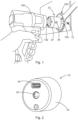
- the Fig. 2 shows a device 10 according to the invention in a schematic perspective view from the outside.
- the device 10 comprises a housing 32, which accommodates all mechanical and/or electronic components of the device 10 and protects them from external influences, in particular from mechanical stress and/or environmental influences such as moisture.
- the housing 32 comprises recesses through which a connection socket 34 and a receiving opening 20 can be reached from the outside through the housing.
- the connection socket 34 can be designed, for example, as a USB socket and can be used to connect the device 10, for example, to an external power supply for charging and/or to supply electrical energy and/or to a data transmission cable for data transmission.
- the receiving opening 20 is designed to accommodate the screwing tool 104. The screwing tool 104 can be pushed through the receiving opening 20, in particular partially or completely, through the device 10.
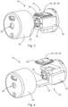
- the Fig. 3 shows the device 10 from the Fig. 2 in an open state in which the housing 32 and the remaining in the closed state of the Device 10 within the housing 32 are shown separately.
- the device 10 comprises a revolution counter 14, which in the closed state of the device 10, as shown in Fig. 2 is shown, is arranged inside the housing 32.
- revolution counter 14 which is designed as a sensory revolution counter 14
- revolutions of the device 10 in particular the revolutions of a screwing tool 104 which extends through the receiving opening 20 of the device 10, as well as the revolutions of a rotary blade 12 which may be connected to the screwing tool 104, can be detected.
- revolutions in the direction of rotation R about the longitudinal axis of the device 10 can be detected, wherein the longitudinal axis of the device 10 is preferably identical to the longitudinal axis of a screwing tool 104 in the receiving opening 20.
- the sensory revolution counter 14 comprises a detection device 16, which is designed as a sensory detection device 16, in particular as an acceleration sensor and/or a gyroscope, by means of which acceleration data and/or rotation data relating to the revolutions of the screwing tool 104, the device 10, and/or the rotary blade 12 can be detected.
- a detection device 16 which is designed as a sensory detection device 16, in particular as an acceleration sensor and/or a gyroscope, by means of which acceleration data and/or rotation data relating to the revolutions of the screwing tool 104, the device 10, and/or the rotary blade 12 can be detected.
- the sensory detection device 16 it is possible to detect acceleration data and/or rotation data relating to the revolutions, from which a number of revolutions can be derived, without the need for prior adaptation and/or calibration of the revolution counter 14 to a specific type and/or type of screwing tool. In this way, it is possible to use the device 10 with the sensory revolution counter 14 universally on any screwing tool and/or to retrofit it
- the sensory revolution counting device 14 of the device 10 comprises an electronic data processing device 22, an electronic control device 30 and an electronic communication unit 28, wherein the data processing device 22, the The communication unit 28 and the control device 30 can be arranged together in a computing unit designed as a chip or can each be designed separately from one another as independent computing units.
- the control device 30, the communication unit 28, the data processing device 22 and the sensory detection device 16 can each be connected to one another in a signal-conducting manner.
- the sensor data detected by the sensory detection device 16, in particular the detected acceleration data and/or rotation data are transmitted from the sensory detection device 16 to the electronic data processing device 22 for evaluation.
- the electronic data processing device 22 evaluates the sensor data, in particular the acceleration data and/or rotation data, wherein in particular a number of revolutions is derived from the data by means of the data processing device 22.
- the number of revolutions derived from the sensor data corresponds to the number of revolutions of the screwing tool 104 in the direction of rotation R, which are carried out, for example, during an adjustment process of a furniture fitting 200.
- the number of revolutions of the screwing tool 104 derived by the data processing device 22 can be output, for example, by the output unit 26 in the form of a illuminated LED and/or on a display device embodied as a display. Furthermore, the sensor data and/or the derived number of revolutions can be transmitted wirelessly, for example via mobile radio and/or Bluetooth, to an external data processing device 302, an external control device 304, an external input unit 306, and/or an external output unit 308 via the connection socket 34 using a cable and/or via the electronic communication unit 28.
- the sensor data acquired by means of the sensory detection device 16 and/or the number of revolutions derived by means of the electronic data processing device 22 can be transmitted to the electronic control device 30 of the revolution counting device 14, wherein the control device 30, on the basis of the acquired sensor data and/or on the basis of the number of revolutions, can control a screwing machine 100 by means of at which the screwing tool 104 is set in rotation.
- the data processing device 22 can derive control specifications for the control device 30 based on the sensor data and transmit them to the control device 30, on the basis of which a screwing machine 100 can be controlled.
- the data processing device 22 can compare a current number of revolutions of the screwing tool 104 derived from the sensor data of the sensory detection device 16 with the intended target number of revolutions and, upon reaching the target number of revolutions, derive control specifications which cause the control device 30 to stop the screwing machine 100.
- a target number of revolutions corresponding to a desired setting of a furniture fitting 200 can be specified by an operator using the input unit 24, wherein the screwdriving machine 100 is automatically stopped by the control device 30 upon reaching the number of revolutions of the screwing tool 104 corresponding to the setting of the furniture fitting 200.
- the desired setting of the furniture fitting is achieved easily, precisely, and reliably.
- the device 10 can also communicate wirelessly with an external control device 304 in the screwing machine 100, so that control specifications derived from the data processing device 22 can be transmitted wirelessly to the screwing machine 100 for control.
- derived numbers of revolutions can be transmitted to an external output unit 308 arranged on the screwing machine 100, for example a display on the screwing machine 100 or an LED on the screwing machine 100, so that the current number of revolutions or a current machine status, for example a signal when the target number of revolutions is reached, is signaled to the screwing machine 100.
- the sensory revolution counter device 14 comprises a Energy storage device 18, which can be designed in particular as a rechargeable battery, in particular as a lithium battery.
- the energy storage device 18 can be used to supply the electrical components of the sensor-based revolution counter, in particular the data processing device 22, the communication unit 28, the control device 30, and the sensor-based detection device 16, with electrical energy.
- the energy storage device 18 can be recharged via the connection socket 34, via which, for example, a USB cable can be connected.
- the Fig. 4 shows the device 10 from Fig. 3 in an open state, wherein the device 10 is shown in an exploded view so that the schematically illustrated structure of the device 10, in particular of the sensor-based revolution counter 14, is more clearly visible.
- the data processing device 22, the communication unit 28, and the control device 30 are arranged together with the connection socket 34 on an electrical circuit board. It is also possible for the connection socket 34, the data processing device 22, the communication unit 28, and the control device 30 to be arranged separately and/or spaced apart from one another instead of on a common circuit board.
- the Fig. 5 shows a furniture fitting 200, which can be adjusted via an adjustment mechanism 202 that can be adjusted by means of a rotary blade 12.
- the furniture fitting 200 is designed as a furniture fitting 200 for a furniture front 212 for opening and closing a cabinet, wherein the furniture front 212 can perform a pivoting movement for opening and closing the cabinet by means of the furniture fitting 200.
- the furniture front 212 is attached to support arms 210, wherein the support arms 210 connect the furniture front 212 to the adjustment mechanism 202.
- the furniture fitting 200 is adjustable, wherein in particular a load-bearing force and/or a counter-torque and/or an opening angle and/or an inclination for the furniture front 212 of the cabinet can be adjusted via the adjustment mechanism 202, so that the cabinet can be adjusted as Intended opens and closes.
- a load-bearing force and/or a counter-torque and/or an opening angle and/or an inclination for the furniture front 212 of the cabinet can be adjusted via the adjustment mechanism 202, so that the cabinet can be adjusted as Intended opens and closes.
- knowledge of the revolutions of the rotary blade 12 when adjusting the adjustment mechanism 202 is necessary, since an intended adjustment of the furniture fitting, for example an intended load-bearing capacity, corresponds to a defined number of revolutions of an adjustment screw 204 of the adjustment mechanism 202.
- the number of revolutions of the rotary blade 12 during an adjustment process of the furniture fitting 200 with a device 10 according to the invention can be detected by counting the revolutions of the screwing tool 104 in order to precisely and reliably implement a desired adjustment of the furniture fitting 200 using the sensory revolution counting device 14 of the device 10.
- the revolutions of the rotary blade 12 can be detected by counting the revolutions of the screwing tool 104, so that the adjustment process of the furniture fitting 200 can be stopped when an intended number of revolutions is reached.
- a suitable number of revolutions for a particular furniture fitting 200 when adjusting the furniture fitting 200 via the adjustment mechanism 202 can be taken, for example, from an online database or from the operating instructions for the furniture fitting 200.
- the Fig. 6 and 7 each show a detailed view of the adjustment mechanism 202 of the furniture fitting 200 in different adjustment states.
- the adjustment mechanism 202 comprises a spring 208, wherein the spring 208 is connected at a first end of the spring 208 to one of the support arms 210 and at its other end to an adjustment screw 204.
- the preload of the spring 208 can be adjusted by adjusting a tensile force on the spring 208.
- the opening moment and/or the load-bearing capacity and/or the counter-torque and/or the opening angle of the furniture fitting 200 can be individually adjusted.
- the adjusting screw 204 of the adjusting mechanism 202 has a crown wheel 206, wherein the adjusting screw 204 can be rotated via the crown wheel 206 by means of a rotary blade 12, wherein by rotating the adjusting screw 204 by means of a rotary blade 12 the end of the spring 208 connected to the adjusting screw 204 travels a travel path V along the adjusting screw 204, wherein the preload force of the spring 208 changes by moving the spring end along the adjusting screw 204.
- a setting state of the furniture fitting 200 is shown, in which a low preload force of the spring 208 is set, resulting in a low counter torque of the furniture fitting 200.
- the Fig. 7 The position of the adjustment mechanism 202 shown results in a high preload force of the spring and thus in a high counter-torque of the furniture fitting 200.
- the adjustment screw 204 is rotated via the crown wheel 206 with a previously defined and intended number of revolutions. Since the number of revolutions of the adjustment screw 204 corresponds to the number of revolutions of a rotary blade 12 and thus of a screwing tool 104, the use of a device 10 according to the invention with the revolution counting device 14 can be used to count the number of revolutions when adjusting the furniture fitting 200, thus ensuring at all times that the furniture fitting 200 is correctly adjusted with the required number of revolutions.
- the operating instructions for a furniture fitting 200 may already contain information on how many turns of the adjusting screw 204 are required to set a desired setting of the furniture fitting 200 via the adjusting mechanism 202 in order to achieve a setting suitable for the furniture.
- Counter torque and/or a suitable opening angle of the furniture front 212 can be used.
- An operator who adjusts the furniture fitting 200 for example, using a screwing machine 100, can use a device 10 according to the invention with a sensory revolution counter 14 to adjust the furniture fitting 200. This device counts the revolutions of the screwing tool 104 and thus the revolutions of the rotary blade 12 and the revolutions of the adjusting screw 204 when adjusting the furniture fitting 200 via the adjustment mechanism 202.
- a furniture fitting 200 can be adjusted quickly, easily, and precisely as intended by using the device 10 with the sensory revolution counter 14.
- other furniture fitting systems than the one shown with spring 208 can also be adjusted, provided that a number of revolutions of the screwing tool 104 corresponds to an intended adjustment of the furniture fitting system.
- fitting systems can also be adjusted that comprise at least one oil damper instead of a spring 208.
- the Fig. 8 shows a mobile terminal 300, which is designed in particular as a smartphone or tablet and comprises an external data processing device 302, an external control device 304, an external input unit 306, an external output unit 308, and an external communication unit 310.
- a computer program product in particular a mobile application, is executed on the mobile terminal 300, by means of which an operator can set, configure, and/or control the device 10, in particular the sensory revolution counter 14 of the device 10, as well as retrieve and/or transmit data.
- the external communication unit 310 of the mobile terminal 300 which can be designed, for example, as a Bluetooth module or mobile radio module of the mobile terminal 300, the mobile terminal 300 can communicate with the communication unit 28 of the device 10.
- Control specifications and/or sensor data and/or numbers of revolutions derived from the sensor data can be exchanged between the communication unit 28 of the device 10 and the external communication unit 310 of the mobile terminal 300.
- the external input unit 306 and/or the external output unit 308 can be designed as a touch-sensitive display, in particular as a touchscreen, of the mobile terminal 300.
- the mobile terminal 300 can display, in particular, the number of revolutions currently derived from the sensor data of the detection device 16 during an adjustment process of a furniture fitting 200.
- an operator can make inputs via the mobile terminal 300.
- desired settings of the furniture fitting 200, in particular intended target revolutions for the screwing tool 104 can be specified via the external input unit 306 via the touchscreen of the mobile terminal 300.
- Inputs made by means of the external input unit 306, in particular predetermined target revolution numbers, can be transmitted via the communication unit 310 of the mobile terminal 300 to the revolution counter 14 of the device 10 and evaluated there, in particular by the data processing device 22.
- the number of revolutions derived by the data processing device 22 of the device 10 can be transmitted to the mobile terminal 300 via the communication unit 28 and displayed there for an operator by the external output unit 308.
- Numbers of revolutions derived by the data processing device 22 and/or derived control specifications can also be transmitted to the mobile terminal 300 and further processed there by the external data processing device 302 and/or the external control device 304.
- sensor data acquired by means of the acquisition device 16 in particular acceleration data and/or rotation data, can be transmitted to the external data processing device 302 and/or the external control device 304 for deriving a number of revolutions and/or for deriving Control specifications and/or for controlling, in particular, the screwing machine 100, are further processed in the mobile terminal.
- the mobile terminal 300 can be configured to transmit control specifications to the screwdriving machine 100 via the communication unit 310 in order to control the screwdriving machine 100 based on the number of revolutions of the screwdriving tool 104.
- the mobile terminal 300 can also have a data memory on which sensor data acquired by the detection device 16, the number of revolutions and/or control specifications derived from the data processing device 22 or the data processing device 302, and target revolution numbers specified by means of the input unit 306 and/or by means of the input unit 24 can be stored.
- prefabricated profiles for example profiles with different target rotational speeds for different furniture fittings 200, can be stored in the data memory of the mobile terminal 300, so that an operator can select a profile suitable for their furniture fitting 200.
- a profile suitable for the furniture fitting 200 and/or a suitable target rotational speed are selected and, based thereon, control specifications are derived, for example.
- the mobile terminal 300 can be used to access, for example, a database, in particular an online database, in which prefabricated profiles and/or suitable target rotational speeds for different furniture fittings 200 are stored and retrievable.
- scannable barcodes and/or QR codes can be stored in the operating instructions for a furniture fitting 200, which can be scanned with a camera of the mobile terminal 300, and suitable target rotational speeds for the respective furniture fitting 200 can be derived therefrom.
Landscapes
- Engineering & Computer Science (AREA)
- Mechanical Engineering (AREA)
- Details Of Spanners, Wrenches, And Screw Drivers And Accessories (AREA)
Applications Claiming Priority (1)
| Application Number | Priority Date | Filing Date | Title |
|---|---|---|---|
| DE102023126896.1A DE102023126896A1 (de) | 2023-10-04 | 2023-10-04 | Vorrichtung zum Vereinfachen der Einstellung eines drehbaren Einstellglieds eines Möbelbeschlags |
Publications (1)
| Publication Number | Publication Date |
|---|---|
| EP4534248A1 true EP4534248A1 (fr) | 2025-04-09 |
Family
ID=92212748
Family Applications (1)
| Application Number | Title | Priority Date | Filing Date |
|---|---|---|---|
| EP24192596.5A Pending EP4534248A1 (fr) | 2023-10-04 | 2024-08-02 | Dispositif pour simplifier le reglage d'un actionneur rotatif d'une ferrure de meuble |
Country Status (2)
| Country | Link |
|---|---|
| EP (1) | EP4534248A1 (fr) |
| DE (1) | DE102023126896A1 (fr) |
Citations (4)
| Publication number | Priority date | Publication date | Assignee | Title |
|---|---|---|---|---|
| DE4343110A1 (de) * | 1992-12-21 | 1994-06-23 | Daimler Benz Ag | Verfahren und eine Vorrichtung zum drehwinkelüberwachten Anziehen oder Lösen von Verschraubungen |
| EP2248632A1 (fr) * | 2009-04-16 | 2010-11-10 | Maeda Metal Industries, Ltd. | Système radiotélégraphique de transmission et de réception de données |
| EP3025823A1 (fr) * | 2014-11-25 | 2016-06-01 | Eduard Wille GmbH & Co KG | Outil d'angle de rotation et de couple |
| DE102015103903A1 (de) * | 2015-03-17 | 2016-09-22 | Juko Technik Gmbh | Kraftschrauber mit direkter Drehwinkel- und/oder Drehmomentmessung |
Family Cites Families (5)
| Publication number | Priority date | Publication date | Assignee | Title |
|---|---|---|---|---|
| DE3216773A1 (de) * | 1982-05-05 | 1983-11-10 | Dr. Staiger, Mohilo + Co GmbH, 7060 Schorndorf | Vorrichtung zum anziehen eines ein gewinde tragenden verbindungselements mit begrenzung des endanzugsdrehmoments |
| US5154242A (en) * | 1990-08-28 | 1992-10-13 | Matsushita Electric Works, Ltd. | Power tools with multi-stage tightening torque control |
| US9243880B2 (en) * | 2014-01-23 | 2016-01-26 | Jonathan DeYaeger | System and method for verifying screw threads |
| DE102015211119A1 (de) * | 2014-06-20 | 2015-12-24 | Robert Bosch Gmbh | Verfahren zum Steuern eines Elektromotors eines Elektrowerkzeuges |
| WO2017147437A1 (fr) * | 2016-02-25 | 2017-08-31 | Milwaukee Electric Tool Corporation | Outil mécanique comportant un capteur de position de sortie |
-
2023
- 2023-10-04 DE DE102023126896.1A patent/DE102023126896A1/de active Pending
-
2024
- 2024-08-02 EP EP24192596.5A patent/EP4534248A1/fr active Pending
Patent Citations (4)
| Publication number | Priority date | Publication date | Assignee | Title |
|---|---|---|---|---|
| DE4343110A1 (de) * | 1992-12-21 | 1994-06-23 | Daimler Benz Ag | Verfahren und eine Vorrichtung zum drehwinkelüberwachten Anziehen oder Lösen von Verschraubungen |
| EP2248632A1 (fr) * | 2009-04-16 | 2010-11-10 | Maeda Metal Industries, Ltd. | Système radiotélégraphique de transmission et de réception de données |
| EP3025823A1 (fr) * | 2014-11-25 | 2016-06-01 | Eduard Wille GmbH & Co KG | Outil d'angle de rotation et de couple |
| DE102015103903A1 (de) * | 2015-03-17 | 2016-09-22 | Juko Technik Gmbh | Kraftschrauber mit direkter Drehwinkel- und/oder Drehmomentmessung |
Also Published As
| Publication number | Publication date |
|---|---|
| DE102023126896A1 (de) | 2025-04-10 |
Similar Documents
| Publication | Publication Date | Title |
|---|---|---|
| EP2096425B1 (fr) | Dispositif d'actionnement destiné au calibrage de clés dynamométriques | |
| DE102017104224B4 (de) | Überwachungssystem und Überwachungsverfahren zur Schraubenverbindung | |
| EP3359351B2 (fr) | Dispositif de préhension à régulateur intégré | |
| DE60032194T2 (de) | Anzieh-Werkzeug mit austauschbarem Einsatz | |
| EP3020512B1 (fr) | Outil et procede de traitement d'une piece ayant un element d'outil | |
| DE102015226734A1 (de) | Industrielles Gerät und tragbare Vorrichtung | |
| EP3571017B1 (fr) | Procédé et dispositif de serrage d'assemblage à vis | |
| DE102020127488A1 (de) | Vorrichtung zur automatisierten Herstellung von Schraubverbindungen | |
| DE102011109133B4 (de) | Transportables Schraubwerkzeug mit integriertem Schaltelement | |
| EP4045232A1 (fr) | Dispositif d'assistance, appareil d'outil et procédé permettant de faire fonctionner un appareil d'outil | |
| EP3302899A1 (fr) | Outil d'assemblage de bouchons et procédé d'assemblage | |
| EP4534248A1 (fr) | Dispositif pour simplifier le reglage d'un actionneur rotatif d'une ferrure de meuble | |
| DE102009056492A1 (de) | Vertikales Bearbeitungszentrum in Gantry-Bauform mit einer Auswuchteinrichtung für den Werkstücktisch | |
| DE202014009065U1 (de) | Messbank zur Überprüfung und Kalibrierung von gyroskopisch messenden Schraubwerkzeugen | |
| US6085564A (en) | Device for setting the adjustable rollers of a straightening unit | |
| EP3049214B1 (fr) | Machine-outil munie d'un dispositif de mesure de dureté | |
| DE102016218572A1 (de) | Handwerkzeugmaschine mit einem drehbaren Trommelmagazin | |
| DE202005019060U1 (de) | Greifvorrichtung | |
| EP2279057B1 (fr) | Dispositif pour le posage d'une paumelle | |
| EP3153280B1 (fr) | Outil avec interface universelle pour interface d'entraînement | |
| DE102016222700A1 (de) | Werkzeugmaschinenvorrichtung und Verfahren zum Betreiben einer Sensoreinheit | |
| DE102014016892B3 (de) | Messbank und Messverfahren zur Überprüfung und Kalibrierung von gyroskopisch messenden Schraubwerkzeugen | |
| DE3318910A1 (de) | Verfahren und einrichtung zum programmieren eines elektronischen schraubenschluessels | |
| DE3801516A1 (de) | Greifersystem fuer biegeschlaffe teile | |
| EP4000795A1 (fr) | Dispositif de vissage destiné à la mise en uvre automatisée d'un procédé de vissage |
Legal Events
| Date | Code | Title | Description |
|---|---|---|---|
| PUAI | Public reference made under article 153(3) epc to a published international application that has entered the european phase |
Free format text: ORIGINAL CODE: 0009012 |
|
| STAA | Information on the status of an ep patent application or granted ep patent |
Free format text: STATUS: THE APPLICATION HAS BEEN PUBLISHED |
|
| AK | Designated contracting states |
Kind code of ref document: A1 Designated state(s): AL AT BE BG CH CY CZ DE DK EE ES FI FR GB GR HR HU IE IS IT LI LT LU LV MC ME MK MT NL NO PL PT RO RS SE SI SK SM TR |
|
| STAA | Information on the status of an ep patent application or granted ep patent |
Free format text: STATUS: REQUEST FOR EXAMINATION WAS MADE |
|
| 17P | Request for examination filed |
Effective date: 20250930 |