EP4534307A1 - Luftstromerzeugungssystem - Google Patents
Luftstromerzeugungssystem Download PDFInfo
- Publication number
- EP4534307A1 EP4534307A1 EP22944059.9A EP22944059A EP4534307A1 EP 4534307 A1 EP4534307 A1 EP 4534307A1 EP 22944059 A EP22944059 A EP 22944059A EP 4534307 A1 EP4534307 A1 EP 4534307A1
- Authority
- EP
- European Patent Office
- Prior art keywords
- airflow
- air
- generation system
- cold
- cabin
- Prior art date
- Legal status (The legal status is an assumption and is not a legal conclusion. Google has not performed a legal analysis and makes no representation as to the accuracy of the status listed.)
- Pending
Links
Images





Classifications
-
- B—PERFORMING OPERATIONS; TRANSPORTING
- B60—VEHICLES IN GENERAL
- B60H—ARRANGEMENTS OF HEATING, COOLING, VENTILATING OR OTHER AIR-TREATING DEVICES SPECIALLY ADAPTED FOR PASSENGER OR GOODS SPACES OF VEHICLES
- B60H1/00—Heating, cooling or ventilating devices
- B60H1/32—Cooling devices
-
- B—PERFORMING OPERATIONS; TRANSPORTING
- B60—VEHICLES IN GENERAL
- B60H—ARRANGEMENTS OF HEATING, COOLING, VENTILATING OR OTHER AIR-TREATING DEVICES SPECIALLY ADAPTED FOR PASSENGER OR GOODS SPACES OF VEHICLES
- B60H1/00—Heating, cooling or ventilating devices
- B60H1/24—Ventilating devices where the heating or cooling is irrelevant
- B60H1/241—Ventilating devices where the heating or cooling is irrelevant characterised by the location of ventilation devices in the vehicle
- B60H1/245—Ventilating devices where the heating or cooling is irrelevant characterised by the location of ventilation devices in the vehicle located in the roof
-
- B—PERFORMING OPERATIONS; TRANSPORTING
- B60—VEHICLES IN GENERAL
- B60H—ARRANGEMENTS OF HEATING, COOLING, VENTILATING OR OTHER AIR-TREATING DEVICES SPECIALLY ADAPTED FOR PASSENGER OR GOODS SPACES OF VEHICLES
- B60H1/00—Heating, cooling or ventilating devices
- B60H1/00007—Combined heating, ventilating, or cooling devices
- B60H1/00207—Combined heating, ventilating, or cooling devices characterised by the position of the HVAC devices with respect to the passenger compartment
- B60H2001/00235—Devices in the roof area of the passenger compartment
Definitions
- the present invention relates to an airflow generation system that is used to reduce cabin temperature in an automobile or another of a variety of vehicles.
- Patent Citation 1 A prior-art example of an airflow generation system such as is described above is described in, for example, Patent Citation 1.
- the airflow generation system described in Patent Citation 1 comprises an air-conditioning device disposed on a roof of a vehicle and a circulation device disposed in a cabin.
- the air-conditioning device takes in cabin air from an air-conditioning intake port into an air-conditioning communication passage, and blows air cooled by an evaporator in the air-conditioning communication passage out to the cabin from an air blowout port.
- the circulation device includes a circulation blower, takes in air blown out from an air-conditioning blowout port toward a circulation intake port into a circulation communication passage, and blows the air from a circulation blowout port toward an air-conditioning intake port.
- Patent Citation 1 Japanese Laid-open Patent Application No. 2019-182118
- the present invention was devised in consideration of the situation of the prior art described above, it being an object of the invention to provide an airflow generation system that can reduce the temperature of the entire cabin using a small amount of energy.
- An airflow generation system comprises a cold source that is disposed on a roof panel of a vehicle and that has a radiant cooling function for maintaining a lower temperature than a temperature of a cabin, a roof trim disposed on an inner side of the roof panel, a cold airflow path formed between the cold source and the roof trim, an air inflow port that allows cabin air to flow into the cold airflow path, and an air outflow port that allows air in the cold airflow path to flow out to the cabin.
- the airflow generation system is characterized by comprising an airflow generator that generates a cold airflow in the cold airflow path in a direction from the air inflow port to the air outflow port, an airflow circulating in a direction from the air outflow port side to the air inflow port side being generated in the cabin.
- the airflow generator generates a cold airflow in the cold airflow path in a direction from the air inflow port to the air outflow port. That is, in the airflow generation system, since cabin air that has flowed into the cold airflow path from the air inflow port is cooled by a cold source having a radiant cooling function, a cold airflow is generated in the cold airflow path merely due to the airflow generator being driven. The airflow generation system then causes cold air to flow out from the air outflow port to the cabin. As a result, a circulating airflow, which is a cold airflow in a direction from the air outflow port side to the air inflow port side, is generated in the cabin, and the temperature of the cabin is reduced.
- a cold airflow in the cold airflow path and a circulating airflow in the cabin are generated merely due to the airflow generator being driven, and it is possible to reduce the temperature of the entire cabin using a small amount of energy.
- FIG. 1 illustrates a first embodiment of an airflow generation system according to the present invention.
- a vehicle V depicted therein, for which the left direction in the drawing is forward, has a roof panel R and a windshield WS, and inside a cabin 50 there are provided a front seat FS, a rear seat RS, a dashboard D, a steering wheel H, etc.
- the airflow generation system shown in Figure 1 comprises, as a basic configuration, a cold source 1 that is disposed on the roof panel R of the vehicle V and that has a radiant cooling function for maintaining a lower temperature than a temperature of the cabin 50, a roof trim T disposed on an inner side of the roof panel R, and a cold airflow path 2 formed between the cold source 1 and the roof trim T.
- Figure 1 schematically depicts the components for the sake of convenience, and accurate positions, sizes, and other features of the components are not limited to those in the drawing.
- the airflow generation system also comprises an air inflow port 3 that allows air in the cabin 50 to flow into the cold airflow path 2, an air outflow port 4 that allows air in the cold airflow path 2 to flow out to the cabin 50, and an airflow generator 5 that generates a cold airflow F1 in the cold airflow path 2 in a direction from the air inflow port 3 to the air outflow port 4.
- the airflow generation system generates a circulating airflow F2 in the cabin 50 in a direction from an air outflow port 4 side to an air inflow port 3 side.
- the cold source 1 is well known as a cooling sheet or structure various fields such as mobile bodies and buildings, and has a radiant cooling function.
- the cold source 1 is provided on an outer panel of the roof panel R.
- the air outflow port 4 can be disposed forward of the center of the roof trim T in the vehicle front-rear direction, and in this embodiment, the air outflow port 4 is disposed at a vehicle front end of the roof trim T.
- airflow generator 5 there are no particular limitations in regard to the airflow generator 5 as long as a unidirectional airflow is generated in the cold airflow path 2; typically a fan is used.
- the airflow generator 5 of this embodiment is disposed inside the cold airflow path 2, in the center in the vehicle front-rear direction.
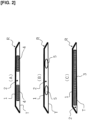
- airflow generators 5 can be disposed in multiple locations in the vehicle left-right direction, and in this embodiment, airflow generators 5, 5 are disposed in two locations in the vehicle left-right direction as shown in Figure 2(B) .
- the airflow generators 5 generate a cold airflow F1 in the cold airflow path 2 in a direction from the air inflow port 3 to the air outflow ports 4, i.e., a direction from the rear of the vehicle to the front of the vehicle.
- the quantity and placement of airflow generators 5 is not limited.
- the airflow generation system of this embodiment also comprises an airflow controller 6 that controls the airflow generators 5. Among functions of driving and stopping the airflow generators 5 and adjusting an airflow rate, at least the functions driving and stopping are provided to the airflow controller 6, but in this embodiment, the airflow controller 6 also has a function of adjusting the airflow rate.
- the airflow rate can be adjusted by changing an output of the airflow generators (fans) 5.
- the airflow controller 6 has an operation unit that is manually operated, and can be operated in conjunction with an automobile air conditioner 7.
- a temperature detector 8 is provided to detect the temperature of the cabin 50, and the airflow generators 5 and the automobile air conditioner 7 can be controlled based on of the temperature detected by the temperature detector 8.
- the airflow generators 5 generate a cold airflow F1 in the cold airflow path 2 in a direction from the air inflow port 3 to the air outflow ports 4. That is, in the airflow generation system, air in the cabin 50, having been caused to flow into the cold airflow path 2 from the air inflow port 3, is cooled by the cold source 1 having the radiant cooling function, and the cold airflow F1 is therefore generated in the cold airflow path 2 merely due to the airflow generators 5 being driven. The airflow generation system then causes cold air to flow out from the air outflow ports 4 to the cabin 50.
- a circulating airflow F2 which is a cold airflow in a direction from the air outflow ports 4 side to the air inflow port 3, i.e., in a direction from the front of the vehicle to the rear, and the temperature of the cabin 50 is reduced.
- air that has flowed to the rear of the cabin 50 is taken into the cold airflow path 2 from the air inflow port 3 and cooled again.
- the upper surfaces of the dashboard D and the instrument panel which are heat-radiating areas, are cooled in a concentrated manner, and the temperature of the cabin 50 is quickly reduced.
- the airflow generators 5 are disposed inside the cold airflow path 2, whereby a pressure difference is created in the cold airflow path 2, a cold airflow F1 having a sufficient flow rate can be easily generated, and the interior appearance of the cabin 50 can be improved by visually hiding the instruments.
- the airflow generators 5 being disposed in multiple locations in the vehicle left-right direction, the flow rate of the cold airflow F1 is increased, whereby the flow rate of the circulating airflow F2 is increased, and the function of cooling the entire cabin 50 can be further improved.
- the airflow generation system described above comprises a temperature detector 8 that detects the temperature of the cabin 50, and the airflow generators 5 are controlled based on of the temperature detected by the temperature detector 8, whereby automatic control is made possible and the airflow generation system can be operated in conjunction with the automobile air conditioner 7. Since the airflow generation system functions as a part of the automobile air conditioner 7, a device for controlling the automobile air conditioner, which is provided with the airflow generation system described above, can accordingly reduce energy required for air conditioning.
- FIGS 3 and 4 are drawings used to describe second through fourth embodiments of the airflow generation system according to the present invention.
- the same components as those in the first embodiment are denoted by the same reference numerals, and detailed description thereof shall be omitted.
- the airflow generation system comprises an airstream direction adjustment mechanism 60 that changes a flow direction of air flowing out to the cabin 50, as shown in Figure 3 .
- the airstream direction adjustment mechanism 60 is provided with a rectangular fixed frame 61 attached to an air outflow port (reference numeral 4 in Figure 1 ) as shown in Figures 3(A) and (B) , and a rectangular movable frame 62 attached to an inner side of the fixed frame 61, as shown in Figure 3(C) .
- the fixed frame 61 and the movable frame 62 are combined with each other such that contact surfaces thereof form a spherical or curved pair.
- a plurality of louvers 63 rotatably supported by vertical shafts are arranged inside the movable frame 62.
- a common link 65 having a left-right operation part 64 is connected to the louvers 63.
- the movable frame 62 also has, at a lower part thereof, an upward/downward operation part 66 that passes through the fixed frame 61 in a downward direction.
- An airflow generation system comprising such an airstream direction adjustment mechanism 60 makes it possible to obtain the same action and effect as the first embodiment, select airstream direction in accordance with occupant preference, and further improve convenience.
- the configuration of the airstream direction adjustment mechanism 60 is not limited to that of the embodiment described above; the movable component may be driven by a motor, and as component such as a throttle for adjusting airstream quantity may be added.
- the airflow generators 5 are disposed outside the cold airflow path 2, in at least one of the air inflow port 3 and the air outflow ports 4.
- the airflow generators 5 are disposed outside the cold airflow path 2 and outside the air outflow ports 4.
- the airflow generation system shown in Figure 4(B) is configured such that the airflow generators 5 are disposed outside the cold airflow path 2 and outside the air inflow port 3.
- pressure is increased in the cold airflow path 2
- the air in the cabin 50 is sent from the air inflow port 3 into the cold airflow path 2, and the sent air is cooled by the cold source 1.
- the airflow generators 5 can be disposed in both the air inflow port 3 and the air outflow ports 4, the airflow generators 5 can be disposed both inside and outside the cold airflow path 2, and the positions and placement locations of the airflow generators 5 can be freely selected.
- the portions measured for temperature were a heater portion of the dashboard, a windshield portion, a roof portion, and a head portion of the driver seat.
- Condition 4 A partition was disposed in the cold airflow path 2, and a front-to-rear airflow was generated.
- Condition 5 A defroster was operated.
- Condition 6 A partition was disposed in the cold airflow path 2, intake temperature was fixed, and a rear-to-front airflow was generated.
- Condition 7 A partition was disposed in the cold airflow path 2, intake temperature was changed, and a front-to-rear airflow was generated.
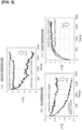
- Figure 5 shows the results of testing using conditions 1 and 2.
- the test procedure was as follows: in the same configuration as that of the airflow generating system shown in Figure 1 , a heater and a chiller were operated for 90 minutes, and the airflow generators 5 were then operated to measure temperature change over time.
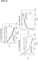
- Figure 6 shows the results of testing using conditions 3 and 7.
- the test procedure was the same as that of the test shown in Figure 5 , but the temperature of intake into the cold airflow path 2 was kept uniform.
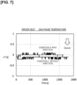
- Figure 7 shows the results of testing using conditions 1 and 3. As is clear from Figure 7 , in the head portion of the driver seat, under any of the conditions, there was no fluctuation in temperature or in the amount of temperature change, and the cabin 50 cooled easily regardless of whether or not there was a partition.
- Figure 8 shows the results of testing using conditions 3 and 5. As is clear from Figures 8(A) and 8(B) , it was found that in the head portion of the driver seat, air does not flow smoothly into the narrow cold airflow path 2 because the defroster is being operated, and heat exchange does not occur readily, but the amount of temperature change becomes large in the roof portion due to the cold source 1.
- Figure 9 shows the results of testing using conditions 4 and 7. As is clear from Figures 9(A) to 9(C) , it was found that when the air flowing into the cold airflow path 2 is warm air or cold air, the cooling speed increases when the air is cold, but the temperature reached is approximately the same in both cases.
- the temperature of the cabin 50 can be minimized to a further extent when the cold airflow F1 is generated in the cold airflow path 2 in a rearward direction from the front than when a defroster is operated.
- An airflow generation device can most efficiently minimize the temperature of the cabin 50 by generating a cold airflow F1 in the cold airflow path 2 in a forward direction from the rear, as shown in Figure 1 .
- the configuration of the airflow generation system according to the present invention is not limited to the embodiments described above, and can be changed as appropriate within a range that does not deviate from the scope of the present invention, depending on the structure inside the vehicle cabin and other factors.
Landscapes
- Physics & Mathematics (AREA)
- Thermal Sciences (AREA)
- Engineering & Computer Science (AREA)
- Mechanical Engineering (AREA)
- Air-Conditioning For Vehicles (AREA)
Applications Claiming Priority (1)
| Application Number | Priority Date | Filing Date | Title |
|---|---|---|---|
| PCT/JP2022/022304 WO2023233579A1 (ja) | 2022-06-01 | 2022-06-01 | 気流発生システム |
Publications (2)
| Publication Number | Publication Date |
|---|---|
| EP4534307A1 true EP4534307A1 (de) | 2025-04-09 |
| EP4534307A4 EP4534307A4 (de) | 2025-12-17 |
Family
ID=89026058
Family Applications (1)
| Application Number | Title | Priority Date | Filing Date |
|---|---|---|---|
| EP22944059.9A Pending EP4534307A4 (de) | 2022-06-01 | 2022-06-01 | Luftstromerzeugungssystem |
Country Status (4)
| Country | Link |
|---|---|
| EP (1) | EP4534307A4 (de) |
| JP (1) | JPWO2023233579A1 (de) |
| CN (1) | CN119343256A (de) |
| WO (1) | WO2023233579A1 (de) |
Families Citing this family (1)
| Publication number | Priority date | Publication date | Assignee | Title |
|---|---|---|---|---|
| CN118617945B (zh) * | 2024-08-12 | 2025-01-14 | 比亚迪股份有限公司 | 车辆和车辆的控制方法 |
Family Cites Families (11)
| Publication number | Priority date | Publication date | Assignee | Title |
|---|---|---|---|---|
| JPS6055509U (ja) * | 1983-09-26 | 1985-04-18 | 富士重工業株式会社 | 車両用空調装置 |
| JP3575119B2 (ja) * | 1995-07-21 | 2004-10-13 | 三菱自動車工業株式会社 | 自動車の空調システム |
| JP5239717B2 (ja) * | 2008-10-06 | 2013-07-17 | 株式会社デンソー | 除加湿装置 |
| JP2014202426A (ja) * | 2013-04-05 | 2014-10-27 | 株式会社デンソー | 加湿装置 |
| JP6394521B2 (ja) * | 2014-08-21 | 2018-09-26 | 株式会社デンソー | 加湿装置 |
| JP6304164B2 (ja) * | 2015-07-29 | 2018-04-04 | 株式会社デンソー | 加湿装置 |
| JP6547639B2 (ja) * | 2016-01-22 | 2019-07-24 | 株式会社デンソー | 車両用空調装置 |
| JP2017178277A (ja) * | 2016-03-31 | 2017-10-05 | 株式会社Subaru | 車両用空調装置 |
| JP7118016B2 (ja) * | 2018-03-02 | 2022-08-15 | 大阪瓦斯株式会社 | 放射冷却装置 |
| JP7309324B2 (ja) | 2018-04-06 | 2023-07-18 | 本田技研工業株式会社 | 車両空調システム |
| JP2020032913A (ja) * | 2018-08-31 | 2020-03-05 | 本田技研工業株式会社 | 車両空調システム及びその制御方法 |
-
2022
- 2022-06-01 CN CN202280096511.0A patent/CN119343256A/zh active Pending
- 2022-06-01 EP EP22944059.9A patent/EP4534307A4/de active Pending
- 2022-06-01 WO PCT/JP2022/022304 patent/WO2023233579A1/ja not_active Ceased
- 2022-06-01 JP JP2024524070A patent/JPWO2023233579A1/ja active Pending
Also Published As
| Publication number | Publication date |
|---|---|
| CN119343256A (zh) | 2025-01-21 |
| JPWO2023233579A1 (de) | 2023-12-07 |
| EP4534307A4 (de) | 2025-12-17 |
| WO2023233579A1 (ja) | 2023-12-07 |
Similar Documents
| Publication | Publication Date | Title |
|---|---|---|
| US6196308B1 (en) | Automotive vehicle climate control system | |
| KR101445649B1 (ko) | 차량용 공조 장치 | |
| JP4883080B2 (ja) | 車両用空調装置 | |
| US20090038774A1 (en) | Air conditioner for vehicle | |
| JPH1067218A (ja) | 日射に関係して調整できる空気案内装置を備えた走行車の空調装置 | |
| JPH11254937A (ja) | 車両用空調装置 | |
| US20130059522A1 (en) | Air conditioner for vehicle | |
| JPH11235914A (ja) | 車両用空調装置 | |
| JP2000233639A (ja) | 車両用空調装置 | |
| US11225121B2 (en) | Vehicle air conditioner | |
| WO2013088727A1 (ja) | 車両用空調装置 | |
| CN111319421B (zh) | 用于控制空调中的内部/外部空气的系统 | |
| US11820201B2 (en) | Method for controlling vehicle HVAC system | |
| JP2018043727A (ja) | 車両用空調装置 | |
| JP4581906B2 (ja) | 車両用空調装置 | |
| JP3316808B2 (ja) | 電気自動車の換気兼走行用モータ冷却装置 | |
| WO2023233579A1 (ja) | 気流発生システム | |
| JPH11189023A (ja) | 車両用空調装置 | |
| US12358346B2 (en) | Air conditioning device for vehicle | |
| JP2000219024A (ja) | 自動車用補助空調装置 | |
| JPH09142131A (ja) | 車載用空調装置 | |
| JPH11254945A (ja) | 車両用空調装置 | |
| JP3680443B2 (ja) | 車両後席用空調装置 | |
| JP7309324B2 (ja) | 車両空調システム | |
| JPH11129727A (ja) | 車両用空調装置 |
Legal Events
| Date | Code | Title | Description |
|---|---|---|---|
| STAA | Information on the status of an ep patent application or granted ep patent |
Free format text: STATUS: THE INTERNATIONAL PUBLICATION HAS BEEN MADE |
|
| PUAI | Public reference made under article 153(3) epc to a published international application that has entered the european phase |
Free format text: ORIGINAL CODE: 0009012 |
|
| STAA | Information on the status of an ep patent application or granted ep patent |
Free format text: STATUS: REQUEST FOR EXAMINATION WAS MADE |
|
| 17P | Request for examination filed |
Effective date: 20241218 |
|
| AK | Designated contracting states |
Kind code of ref document: A1 Designated state(s): AL AT BE BG CH CY CZ DE DK EE ES FI FR GB GR HR HU IE IS IT LI LT LU LV MC MK MT NL NO PL PT RO RS SE SI SK SM TR |
|
| DAV | Request for validation of the european patent (deleted) | ||
| DAX | Request for extension of the european patent (deleted) | ||
| A4 | Supplementary search report drawn up and despatched |
Effective date: 20251113 |
|
| RIC1 | Information provided on ipc code assigned before grant |
Ipc: B60H 1/32 20060101AFI20251107BHEP Ipc: B60H 1/34 20060101ALI20251107BHEP |