EP4534417A2 - Kabinenbelegungssensor für die klimaanlage von flugzeugen - Google Patents
Kabinenbelegungssensor für die klimaanlage von flugzeugen Download PDFInfo
- Publication number
- EP4534417A2 EP4534417A2 EP24204054.1A EP24204054A EP4534417A2 EP 4534417 A2 EP4534417 A2 EP 4534417A2 EP 24204054 A EP24204054 A EP 24204054A EP 4534417 A2 EP4534417 A2 EP 4534417A2
- Authority
- EP
- European Patent Office
- Prior art keywords
- cabin
- zone
- occupancy sensor
- electronic controller
- air
- Prior art date
- Legal status (The legal status is an assumption and is not a legal conclusion. Google has not performed a legal analysis and makes no representation as to the accuracy of the status listed.)
- Pending
Links
Images


Classifications
-
- B—PERFORMING OPERATIONS; TRANSPORTING
- B64—AIRCRAFT; AVIATION; COSMONAUTICS
- B64D—EQUIPMENT FOR FITTING IN OR TO AIRCRAFT; FLIGHT SUITS; PARACHUTES; ARRANGEMENT OR MOUNTING OF POWER PLANTS OR PROPULSION TRANSMISSIONS IN AIRCRAFT
- B64D13/00—Arrangements or adaptations of air-treatment apparatus for aircraft crew or passengers, or freight space
- B64D13/06—Arrangements or adaptations of air-treatment apparatus for aircraft crew or passengers, or freight space the air being conditioned
- B64D13/08—Arrangements or adaptations of air-treatment apparatus for aircraft crew or passengers, or freight space the air being conditioned the air being heated or cooled
-
- B—PERFORMING OPERATIONS; TRANSPORTING
- B64—AIRCRAFT; AVIATION; COSMONAUTICS
- B64D—EQUIPMENT FOR FITTING IN OR TO AIRCRAFT; FLIGHT SUITS; PARACHUTES; ARRANGEMENT OR MOUNTING OF POWER PLANTS OR PROPULSION TRANSMISSIONS IN AIRCRAFT
- B64D13/00—Arrangements or adaptations of air-treatment apparatus for aircraft crew or passengers, or freight space
- B64D13/06—Arrangements or adaptations of air-treatment apparatus for aircraft crew or passengers, or freight space the air being conditioned
- B64D2013/0603—Environmental Control Systems
- B64D2013/0625—Environmental Control Systems comprising means for distribution effusion of conditioned air in the cabin
-
- B—PERFORMING OPERATIONS; TRANSPORTING
- B64—AIRCRAFT; AVIATION; COSMONAUTICS
- B64D—EQUIPMENT FOR FITTING IN OR TO AIRCRAFT; FLIGHT SUITS; PARACHUTES; ARRANGEMENT OR MOUNTING OF POWER PLANTS OR PROPULSION TRANSMISSIONS IN AIRCRAFT
- B64D13/00—Arrangements or adaptations of air-treatment apparatus for aircraft crew or passengers, or freight space
- B64D13/06—Arrangements or adaptations of air-treatment apparatus for aircraft crew or passengers, or freight space the air being conditioned
- B64D2013/0603—Environmental Control Systems
- B64D2013/0655—Environmental Control Systems with zone or personal climate controls
-
- B—PERFORMING OPERATIONS; TRANSPORTING
- B64—AIRCRAFT; AVIATION; COSMONAUTICS
- B64D—EQUIPMENT FOR FITTING IN OR TO AIRCRAFT; FLIGHT SUITS; PARACHUTES; ARRANGEMENT OR MOUNTING OF POWER PLANTS OR PROPULSION TRANSMISSIONS IN AIRCRAFT
- B64D13/00—Arrangements or adaptations of air-treatment apparatus for aircraft crew or passengers, or freight space
- B64D13/06—Arrangements or adaptations of air-treatment apparatus for aircraft crew or passengers, or freight space the air being conditioned
- B64D2013/0603—Environmental Control Systems
- B64D2013/0688—Environmental Control Systems with means for recirculating cabin air
Definitions
- This disclosure relates generally to cabin air controller systems on aircraft and, more particularly, to ventilation and climate control on aircraft.
- a method for controlling an atmosphere within an aircraft.
- the method includes sensing, by at least one cabin occupancy sensor, a number of empty seats within a cabin of the aircraft. Data representative of the number of empty seats from the at least one cabin occupancy sensor is communicated by the at least one cabin occupancy sensor to an electronic controller.
- the electronic controller is in communication with a cabin air circulation system and at least one environmental control system.
- the electronic controller sends a flow command to both the at least one environmental control system and the cabin air circulation system to adjust a rate of a total air inflow into the cabin based on the number of empty seats sensed by the at least one cabin occupancy sensor.
- a method for controlling an atmosphere within an aircraft includes sensing, by at least one cabin occupancy sensor, surface temperatures of passengers within a first zone of a cabin of the aircraft.
- the at least one cabin occupancy sensor communicates data representative of the surface temperatures of the passengers within the first zone to an electronic controller.
- the electronic controller is in communication with a first environmental control system.
- the electronic controller sends a first temperature command to the first environmental control system to adjust a temperature of a first air inflow into the first zone of the cabin based on the surface temperatures of the passengers within the first zone sensed by the at least one cabin occupancy sensor.
- First ECS 13a and second ECS 13b can each include air conditioning units or packs 22, pack outlet ducts 24, hot air trim systems 26, and trim outlet ducts 28.
- First cabin air circulation system 16a and second cabin air circulation system 16b can each include air mixing units 30, return ducts 32, air distribution system 34 with one or more conduits 36, recirculation fan 38, cabin outlets 40, cabin vents 42, and filter 44.
- air controller system 10 is illustrated and described herein with reference to aircraft 11, the systems and techniques discussed herein may be used for a variety of air controller systems 10.
- cabin 12 may be replaced with any closed volume to be conditioned.
- systems described herein may be used with ship air controller systems, such as submarines and cruise liners for example, personnel carrier air controller systems, bus, trolley, train, or subway air controller systems, or any other air controller system that requires a continual supply of conditioned air.
- Filters 44 are mounted within return ducts 32 and are configured to remove harmful microbes such as bacteria, viruses, spores, fungi and particulate matter from the air exiting cabin 12 as the air flows through filters 44 before entering air mixing units 30.
- filters 44 are shown in FIG. 1 as being arranged adjacent downstream ends of return duct 32, such as directly upstream from an interface between return ducts 32 and air mixing units 30, filters 44 can be arranged at any location within return ducts 32.
- Filters 44 can comprise a HEPA-type filter. However, any suitable filter, or combination of multiple filters is within the scope of this disclosure.
- Recirculation fans 38 are connected to return ducts 32 to establish an overpressure that is used to drive the flow of the recirculating cabin air through filters 44 and into air mixing units 30.
- Occupancy sensors 20 are in wired or wireless communication with controller 18 of air controller system 10 such that controller receives data from occupancy sensors 20.
- Occupancy sensors 20 in cabin 12 can include a built-in processor and non-transitory system memory with stored artificial intelligence (AI) and machine learning software tools to process the data generated by occupancy sensors 20 before sending the data to controller 18.
- AI artificial intelligence
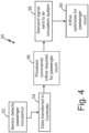
- occupancy sensors 20 sense a number of empty seats 48 and occupied seats 46 within cabin 12, occupancy sensors 20 communicate data representative of the number of empty seats 48 and/or representative of the number of occupied seats 46 to controller 18, which completes second step 54 of logic flow diagram 50 of FIG. 4 .
- controller 18 is in communication with first cabin air circulation system 16a, first ECS 13a, and second ECS 13b.
- third step 56 of logic flow diagram 50 is performed by the processor of controller 18 using the data from occupancy sensors 20 to determine what the rate should be for total air inflow F into cabin 12 based on the number of passengers sensed by occupancy sensors 20.
- Controller 18 can then send flow commands to first cabin air circulation system 16a, second cabin air circulation system 16b, first ECS 13a, and second ECS 13b to adjust a rate of total air inflow F into cabin 12 based on the number of empty seats 48 sensed by cabin occupancy sensors 20, as shown in fourth step 58 and fifth step 60 of logic flow diagram 50 of FIG. 4 .
- Recirculation fans 38 of first cabin air circulation system 16a and second cabin air circulation system 16b can be in communication with controller 18 and can adjust in speed in response to the flow command from controller 18.
- controller 18 can adjust the speed of recirculation fans 38 to achieve the rate of total air inflow F into cabin 12 appropriate for the number of occupied seats 46 sensed by cabin occupancy sensors 20.
- Controller 18 can also adjust the speed at which ECS 13a and ECS 13b provide fresh air inflow to first cabin air circulation system 16a and second cabin air circulation system 16b to help achieve the rate of total air inflow F into cabin 12 appropriate for the number of occupied seats 46 sensed by cabin occupancy sensors 20.
- cabin occupancy sensors 20 can also sense a distribution of the passengers within cabin 12 and thermal gradients within cabin 12, as discussed below with reference to FIGS. 5-8 .
- cabin occupancy sensors 20 sense a distribution of empty seats 48 within cabin 12 of aircraft 11 and can also sense the surface temperatures of the passengers in each of zones 1, 2, and 3.
- cabin occupancy sensors 20 can include a thermal infrared camera that senses the heat signatures of the passengers in zone 1 to determine a first distribution of empty seats within zone 1, and can also use the heat signatures of the passengers in zone 1 to sense surface temperatures of passengers within zone 1 of cabin 12.
- Cabin occupancy sensors 20 can communicate data representative of the first distribution of empty seats 48 within zone 1 to controller 18.
- Cabin occupancy sensors 20 can also communicate data representative of the surface temperatures of the passengers within zone 1 of cabin 12 to controller 18.
- controller 18 can send a first temperature command to first ECS 13a to adjust a temperature of first air inflow F 1 into zone 1 of cabin 12 based on the surface temperatures of the passengers within zone 1 and/or the first distribution of empty seats 48 sensed by cabin occupancy sensors 20. For example, controller 18 can send the first temperature command to first ECS 13a indicating that zone 1 is completely full of passengers and the passengers within zone 1 have an average skin temperature that is above a comfort level set by the flight crew. In response to the first temperature command, first ECS 13a can reduce the amount of medium contributed by hot air trim system 26 of first ECS 13a to first cabin air circulation system 16a, thereby reducing the temperature of first air inflow F 1 into zone 1.
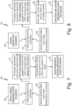
- a processor of controller 18 In the fourth step 72 of the logic flow diagram 62 of FIG. 7 , a processor of controller 18 generates a command signal that will adjust zone temperature control in cabin 12 to account for the flight crew cabin temperature command along with the thermal effects and biases caused by the passenger count in cabin 12.
- controller 18 sends the command signal to hot air trim system 26 of an ECS 13 of air controller system 10.
- hot air trim system 26 responds by increasing or decreasing the amount of hot air that is mixed into total air inflow F such that total air inflow F entering cabin 12 is optimized at a temperature that will cause cabin 12 to reach the temperature targeted by the flight crew.
- the method of the preceding paragraph can optionally include, additionally and/or alternatively, any one or more of the following features, configurations and/or additional components:
- an air controller system for controlling an atmosphere within an aircraft includes a cabin air circulation system and at least one cabin occupancy sensor in a cabin of the aircraft.
- the at least one cabin occupancy sensor is configured to detect a number of empty seats within the cabin.
- An electronic controller is in communication with the cabin air circulation system and the at least one cabin occupancy sensor.
- the electronic controller is configured to receive data from the at least one cabin occupancy sensor representative of the number of empty seats detected by the cabin occupancy sensor.
- the electronic controller is also configured to send commands to the cabin air circulation system based on the number of empty seats detected by the cabin occupancy sensor.
- a method for controlling an atmosphere within an aircraft.
- the method includes sensing, by at least one cabin occupancy sensor, surface temperatures of passengers within a first zone of a cabin of the aircraft.
- the at least one cabin occupancy sensor communicates data representative of the surface temperatures of the passengers within the first zone to an electronic controller.
- the electronic controller is in communication with a first environmental control system.
- the electronic controller sends a first temperature command to the first environmental control system to adjust a temperature of a first air inflow into the first zone of the cabin based on the surface temperatures of the passengers within the first zone sensed by the at least one cabin occupancy sensor.
- FIGS. 1 and 3 show air controller system 10 with first ECS 13a, second ECS 13b, first cabin air circulation system 16a, and second cabin air circulation system 16b
- air controller system 10 can include a single ECS 13 that supplies conditioned air and hot trim air to several different cabin air circulation systems 16 and a valve system that controller 18 manages to customize flow from the single ECS 13 to each of the several different cabin air circulation systems 16.
Landscapes
- Health & Medical Sciences (AREA)
- General Health & Medical Sciences (AREA)
- Pulmonology (AREA)
- Engineering & Computer Science (AREA)
- Aviation & Aerospace Engineering (AREA)
- Air-Conditioning For Vehicles (AREA)
- Air Conditioning Control Device (AREA)
Applications Claiming Priority (1)
| Application Number | Priority Date | Filing Date | Title |
|---|---|---|---|
| US18/479,519 US20250108925A1 (en) | 2023-10-02 | 2023-10-02 | Cabin occupancy sensor for aircraft ecs |
Publications (2)
| Publication Number | Publication Date |
|---|---|
| EP4534417A2 true EP4534417A2 (de) | 2025-04-09 |
| EP4534417A3 EP4534417A3 (de) | 2025-04-23 |
Family
ID=92966521
Family Applications (1)
| Application Number | Title | Priority Date | Filing Date |
|---|---|---|---|
| EP24204054.1A Pending EP4534417A3 (de) | 2023-10-02 | 2024-10-01 | Kabinenbelegungssensor für die klimaanlage von flugzeugen |
Country Status (2)
| Country | Link |
|---|---|
| US (1) | US20250108925A1 (de) |
| EP (1) | EP4534417A3 (de) |
Families Citing this family (1)
| Publication number | Priority date | Publication date | Assignee | Title |
|---|---|---|---|---|
| US20250223982A1 (en) * | 2024-01-08 | 2025-07-10 | The Boeing Company | Pneumatic System Flow Balancing Architecture and Method |
Family Cites Families (13)
| Publication number | Priority date | Publication date | Assignee | Title |
|---|---|---|---|---|
| JP4341142B2 (ja) * | 2000-04-17 | 2009-10-07 | 株式会社島津製作所 | 航空機用空調システム |
| US6454178B1 (en) * | 2001-05-24 | 2002-09-24 | Ford Global Technologies, Inc. | Adaptive controller for an automotive HVAC system |
| US7837541B2 (en) * | 2006-12-13 | 2010-11-23 | The Boeing Company | Method for reducing outside air inflow required for aircraft cabin air quality |
| US9102215B2 (en) * | 2011-10-17 | 2015-08-11 | Ford Global Technologies, Llc | Airflow control in floor mode for vehicle with multiple seating rows |
| US20130231035A1 (en) * | 2012-03-01 | 2013-09-05 | Hamilton Sundstrand Corporation | Active air flow control in aircraft |
| US9889939B2 (en) * | 2012-06-06 | 2018-02-13 | The Boeing Company | Environmental control system and methods of operating same |
| US9302781B2 (en) * | 2014-02-25 | 2016-04-05 | Astronics Advanced Electronic Systems Corp. | Apparatus and method to monitor the occupancy of seating |
| CN107635875B (zh) * | 2015-05-22 | 2021-08-24 | 庞巴迪公司 | 飞行器的机舱中的气流管理 |
| US9896216B2 (en) * | 2016-06-01 | 2018-02-20 | Honeywell Limited | ECO mode ECS logic |
| EP3808658B1 (de) * | 2019-10-14 | 2024-07-31 | Hamilton Sundstrand Corporation | Klimasteuerungsanlage |
| US12151820B2 (en) * | 2020-06-18 | 2024-11-26 | B/E Aerospace, Inc. | Software controlled air flow management |
| EP4171995A4 (de) * | 2020-06-25 | 2024-08-14 | Thales Avionics, Inc. | Sitzluftsterilisationsanordnung für eine sitzvideoanzeigeeinheit |
| DE102020210572A1 (de) * | 2020-08-20 | 2022-02-24 | Diehl Aerospace Gmbh | Kabine für ein Flugzeug mit einer Überwachungsanordnung, Flugzeug mit der Kabine, Überwachungsanordnung und Verfahren zur Überwachung einer Kabine eines Flugzeugs |
-
2023
- 2023-10-02 US US18/479,519 patent/US20250108925A1/en active Pending
-
2024
- 2024-10-01 EP EP24204054.1A patent/EP4534417A3/de active Pending
Also Published As
| Publication number | Publication date |
|---|---|
| EP4534417A3 (de) | 2025-04-23 |
| US20250108925A1 (en) | 2025-04-03 |
Similar Documents
| Publication | Publication Date | Title |
|---|---|---|
| JP3566353B2 (ja) | 旅客機の胴体内部の空調のための空気循環装置 | |
| EP2671801B1 (de) | Klimaanlage und verfahren zu deren betrieb | |
| EP1874625B2 (de) | Systeme und verfahren zur frachtraumklimatisierung unter verwendung von umluft | |
| US20080053126A1 (en) | Aircraft Air-Conditioning System For The Individual Air Conditioning Of Regions Of An Aircraft Cabin With A Liquid Coolant | |
| ES2248008T3 (es) | Sistema de regulacion de corriente de masa de aire con correccion segun la altitud barometrica para un avion comercial. | |
| US20180065752A1 (en) | Aircraft air conditioning system airflow regulation | |
| JP5190057B2 (ja) | 航空機用着氷防止空調システム | |
| EP4534417A2 (de) | Kabinenbelegungssensor für die klimaanlage von flugzeugen | |
| CN102209665B (zh) | 用于在空气混合器的区域中发生泄漏的情况下对飞机机舱紧急通风的方法和系统 | |
| US9592916B2 (en) | Aircraft air conditioning system and method for controlling an aircraft air conditioning system using a bypass valve | |
| US20130295831A1 (en) | Method for controlling an aircraft air conditioning system during maintenance | |
| EP2790939B1 (de) | Temperaturregelung von systemen zur verteilung erwärmter luft in passagierräumen | |
| EP4140890B1 (de) | Thermodynamische steuerung der flugzeugkabinenluft | |
| US9689597B2 (en) | Air-conditioning system for an aircraft, and method for an aircraft | |
| US9290118B2 (en) | Heated flight attendant jumpseats for commercial airplane applications | |
| EP3591302B1 (de) | Belüftungssystem | |
| EP3808658B1 (de) | Klimasteuerungsanlage | |
| CN110471475B (zh) | 温度调节系统和由其实现的应用方法 | |
| US20190352012A1 (en) | Aircraft ventilation system | |
| EP4269246B1 (de) | Verkleidungsmodul mit thermoelektrischem kühler | |
| US11987366B2 (en) | Aircraft cabin air management system | |
| EP3138774A1 (de) | Flugzeugklimatisierungssystem mit reduziertem prozessluftbedarf | |
| HK1109761C (en) | Systems and methods for cargo compartment air conditioning using recirculated air | |
| HK1109761B (en) | Systems and methods for cargo compartment air conditioning using recirculated air |
Legal Events
| Date | Code | Title | Description |
|---|---|---|---|
| PUAI | Public reference made under article 153(3) epc to a published international application that has entered the european phase |
Free format text: ORIGINAL CODE: 0009012 |
|
| STAA | Information on the status of an ep patent application or granted ep patent |
Free format text: STATUS: THE APPLICATION HAS BEEN PUBLISHED |
|
| PUAL | Search report despatched |
Free format text: ORIGINAL CODE: 0009013 |
|
| AK | Designated contracting states |
Kind code of ref document: A2 Designated state(s): AL AT BE BG CH CY CZ DE DK EE ES FI FR GB GR HR HU IE IS IT LI LT LU LV MC ME MK MT NL NO PL PT RO RS SE SI SK SM TR |
|
| AK | Designated contracting states |
Kind code of ref document: A3 Designated state(s): AL AT BE BG CH CY CZ DE DK EE ES FI FR GB GR HR HU IE IS IT LI LT LU LV MC ME MK MT NL NO PL PT RO RS SE SI SK SM TR |
|
| RIC1 | Information provided on ipc code assigned before grant |
Ipc: B64D 13/06 20060101AFI20250319BHEP |
|
| STAA | Information on the status of an ep patent application or granted ep patent |
Free format text: STATUS: REQUEST FOR EXAMINATION WAS MADE |
|
| 17P | Request for examination filed |
Effective date: 20250904 |
|
| STAA | Information on the status of an ep patent application or granted ep patent |
Free format text: STATUS: EXAMINATION IS IN PROGRESS |
|
| 17Q | First examination report despatched |
Effective date: 20260122 |