EP4534440A1 - Adaptateur de récipient de stockage, récipient de stockage et dispositif de stockage - Google Patents
Adaptateur de récipient de stockage, récipient de stockage et dispositif de stockage Download PDFInfo
- Publication number
- EP4534440A1 EP4534440A1 EP23811762.6A EP23811762A EP4534440A1 EP 4534440 A1 EP4534440 A1 EP 4534440A1 EP 23811762 A EP23811762 A EP 23811762A EP 4534440 A1 EP4534440 A1 EP 4534440A1
- Authority
- EP
- European Patent Office
- Prior art keywords
- engagement element
- brims
- reservoir
- pair
- brim
- Prior art date
- Legal status (The legal status is an assumption and is not a legal conclusion. Google has not performed a legal analysis and makes no representation as to the accuracy of the status listed.)
- Pending
Links
Images


Classifications
-
- B—PERFORMING OPERATIONS; TRANSPORTING
- B65—CONVEYING; PACKING; STORING; HANDLING THIN OR FILAMENTARY MATERIAL
- B65D—CONTAINERS FOR STORAGE OR TRANSPORT OF ARTICLES OR MATERIALS, e.g. BAGS, BARRELS, BOTTLES, BOXES, CANS, CARTONS, CRATES, DRUMS, JARS, TANKS, HOPPERS, FORWARDING CONTAINERS; ACCESSORIES, CLOSURES, OR FITTINGS THEREFOR; PACKAGING ELEMENTS; PACKAGES
- B65D83/00—Containers or packages with special means for dispensing contents
- B65D83/14—Containers for dispensing liquid or semi-liquid contents by internal gaseous pressure, i.e. aerosol containers comprising propellant
- B65D83/60—Containers for dispensing liquid or semi-liquid contents by internal gaseous pressure, i.e. aerosol containers comprising propellant with contents and propellant separated
-
- B—PERFORMING OPERATIONS; TRANSPORTING
- B05—SPRAYING OR ATOMISING IN GENERAL; APPLYING FLUENT MATERIALS TO SURFACES, IN GENERAL
- B05B—SPRAYING APPARATUS; ATOMISING APPARATUS; NOZZLES
- B05B9/00—Spraying apparatus for discharge of liquids or other fluent material, without essentially mixing with gas or vapour
- B05B9/03—Spraying apparatus for discharge of liquids or other fluent material, without essentially mixing with gas or vapour characterised by means for supplying liquid or other fluent material
- B05B9/04—Spraying apparatus for discharge of liquids or other fluent material, without essentially mixing with gas or vapour characterised by means for supplying liquid or other fluent material with pressurised or compressible container; with pump
- B05B9/08—Apparatus to be carried on or by a person, e.g. of knapsack type
- B05B9/0805—Apparatus to be carried on or by a person, e.g. of knapsack type comprising a pressurised or compressible container for liquid or other fluent material
- B05B9/0838—Apparatus to be carried on or by a person, e.g. of knapsack type comprising a pressurised or compressible container for liquid or other fluent material supply being effected by follower in container, e.g. membrane or floating piston, or by deformation of container
-
- B—PERFORMING OPERATIONS; TRANSPORTING
- B05—SPRAYING OR ATOMISING IN GENERAL; APPLYING FLUENT MATERIALS TO SURFACES, IN GENERAL
- B05C—APPARATUS FOR APPLYING FLUENT MATERIALS TO SURFACES, IN GENERAL
- B05C11/00—Component parts, details or accessories not specifically provided for in groups B05C1/00 - B05C9/00
- B05C11/11—Vats or other containers for liquids or other fluent materials
-
- A—HUMAN NECESSITIES
- A61—MEDICAL OR VETERINARY SCIENCE; HYGIENE
- A61M—DEVICES FOR INTRODUCING MEDIA INTO, OR ONTO, THE BODY; DEVICES FOR TRANSDUCING BODY MEDIA OR FOR TAKING MEDIA FROM THE BODY; DEVICES FOR PRODUCING OR ENDING SLEEP OR STUPOR
- A61M5/00—Devices for bringing media into the body in a subcutaneous, intra-vascular or intramuscular way; Accessories therefor, e.g. filling or cleaning devices, arm-rests
- A61M5/178—Syringes
- A61M5/20—Automatic syringes, e.g. with automatically actuated piston rod, with automatic needle injection, filling automatically
- A61M5/2053—Media being expelled from injector by pressurised fluid or vacuum
-
- B—PERFORMING OPERATIONS; TRANSPORTING
- B05—SPRAYING OR ATOMISING IN GENERAL; APPLYING FLUENT MATERIALS TO SURFACES, IN GENERAL
- B05C—APPARATUS FOR APPLYING FLUENT MATERIALS TO SURFACES, IN GENERAL
- B05C17/00—Hand tools or apparatus using hand held tools, for applying liquids or other fluent materials to, for spreading applied liquids or other fluent materials on, or for partially removing applied liquids or other fluent materials from, surfaces
- B05C17/005—Hand tools or apparatus using hand held tools, for applying liquids or other fluent materials to, for spreading applied liquids or other fluent materials on, or for partially removing applied liquids or other fluent materials from, surfaces for discharging material from a reservoir or container located in or on the hand tool through an outlet orifice by pressure without using surface contacting members like pads or brushes
- B05C17/00573—Hand tools or apparatus using hand held tools, for applying liquids or other fluent materials to, for spreading applied liquids or other fluent materials on, or for partially removing applied liquids or other fluent materials from, surfaces for discharging material from a reservoir or container located in or on the hand tool through an outlet orifice by pressure without using surface contacting members like pads or brushes the reservoir or container being pneumatically or hydraulically pressurized
-
- B—PERFORMING OPERATIONS; TRANSPORTING
- B65—CONVEYING; PACKING; STORING; HANDLING THIN OR FILAMENTARY MATERIAL
- B65D—CONTAINERS FOR STORAGE OR TRANSPORT OF ARTICLES OR MATERIALS, e.g. BAGS, BARRELS, BOTTLES, BOXES, CANS, CARTONS, CRATES, DRUMS, JARS, TANKS, HOPPERS, FORWARDING CONTAINERS; ACCESSORIES, CLOSURES, OR FITTINGS THEREFOR; PACKAGING ELEMENTS; PACKAGES
- B65D83/00—Containers or packages with special means for dispensing contents
-
- B—PERFORMING OPERATIONS; TRANSPORTING
- B65—CONVEYING; PACKING; STORING; HANDLING THIN OR FILAMENTARY MATERIAL
- B65D—CONTAINERS FOR STORAGE OR TRANSPORT OF ARTICLES OR MATERIALS, e.g. BAGS, BARRELS, BOTTLES, BOXES, CANS, CARTONS, CRATES, DRUMS, JARS, TANKS, HOPPERS, FORWARDING CONTAINERS; ACCESSORIES, CLOSURES, OR FITTINGS THEREFOR; PACKAGING ELEMENTS; PACKAGES
- B65D88/00—Large containers
- B65D88/54—Large containers characterised by means facilitating filling or emptying
-
- E—FIXED CONSTRUCTIONS
- E03—WATER SUPPLY; SEWERAGE
- E03F—SEWERS; CESSPOOLS
- E03F5/00—Sewerage structures
- E03F5/10—Collecting-tanks; Equalising-tanks for regulating the run-off; Laying-up basins
- E03F5/101—Dedicated additional structures, interposed or parallel to the sewer system
Definitions
- an object of the present invention is to provide a reservoir container adapter, a reservoir container, and a reservoir device that can solve the above-described problem.
- a distance W1 between inner walls of the pair of lateral members may be larger than a distance W2 between most protruded points of the pair of brims.
- the pair of lateral members may include rotation stop surfaces that come in contact with short sides of the pair of brims in such a position that the first engagement element and the second engagement element engage with each other.
- the pair of brim-holding claws may include tapered surfaces for the brims to come in contact with when entering the gaps between the brim-holding claws and the base.
- the adapter may be made of resin.
- the first engagement element may include a recessed portion provided in a lower surface of the base, and the second engagement element may include a protruded portion provided on an upper surface of each of the pair of brims.
- a reservoir container adapter is a reservoir container adapter used for the reservoir device, the reservoir container adapter including a base configured to be connected to an air pipe, a blocking portion extending downward from a central portion of the base, and a pair of brim-holding portions provided on opposite short sides of the base and configured to hold the pair of brims, wherein the first engagement element includes a protruded portion provided on an upper surface of each of the pair of brim-holding claws, wherein, when the blocking portion is inserted into the upper opening of the reservoir container and the reservoir container is rotated in one direction, the brims enter gaps between the brim-holding claws and the base and the first engagement element and the second engagement element engage with each other to perform positioning.
- a reservoir container adapter is a reservoir container adapter used for the reservoir device, the reservoir container adapter including a base configured to be connected to an air pipe, a blocking portion extending downward from a central portion of the base, and a pair of brim-holding portions provided on opposite short sides of the base and configured to hold the pair of brims, wherein the first engagement element includes a recessed portion provided in an upper surface of each of the pair of brim-holding claws, wherein, when the blocking portion is inserted into the upper opening of the reservoir container and the reservoir container is rotated in one direction, the brims enter gaps between the brim-holding claws and the base and the first engagement element and the second engagement element engage with each other to perform positioning.
- a reservoir device is a reservoir container adapter used for the reservoir device, the reservoir container adapter including a base configured to be connected to an air pipe, a blocking portion extending downward from a central portion of the base, and a pair of brim-holding portions provided on opposite short sides of the base and configured to hold the pair of brims, wherein the first engagement element includes a recessed portion provided in a lower surface of the base, wherein, when the blocking portion is inserted into the upper opening of the reservoir container and the reservoir container is rotated in one direction, the brims enter gaps between the brim-holding claws and the base and the first engagement element and the second engagement element engage with each other to perform positioning.
- a reservoir container adapter a reservoir container, and a reservoir device that make it possible to confirm that the reservoir container and the reservoir container adapter are in a right connection position even if some dimensional difference occurs due to uneven shrinkage during manufacturing.
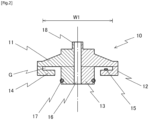
- the gap G is smaller than the thickness of the brim 23, when the brim 23 enters the gap G, the gap G widens due to elastic deformation of the brim-holding claw 14.
- the distance W1 between inner walls of the lateral members 12, 12 is larger than the distance W2 between most protruded points of the brims 23, 23 to be described later.
- the blocking portion 13 is a columnar member extending downward from the central portion of the base 11 and is provided with an annular seal member 17 slightly above its lower end.
- the blocking portion 13 has a through-hole 16, and pressurized air is supplied from the pressurized-air supply source 2 into the reservoir container 20 via the through-hole 16.
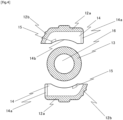
- Fig. 3 (a) is a perspective view illustrating the reservoir container 20 according to the embodiment, and (b) is a side view illustrating the adapter 10.
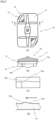
- Fig. 4 is a plan view illustrating elements of the adapter 10 excluding the base 11 and the seal member 17 according to the embodiment.
- the first engagement element 15 is a protruded portion that is substantially parallelogram shaped when viewed from above, the shape is not limited to the illustrated one and a protruded portion of any shape is possible.
- the adapter 10 has a substantially rectangular shape with opposite two corners rounded when viewed from above, and the base 11 is provided with the windows 19 near the rounded corners.
- the first engagement elements 15 are visible through the windows 19.
- the window 19 is formed by extracting a mold (insert) for forming the first engagement element when the adapter 10 is injection molded. In a case where no window 19 is provided, there is an issue that the protruded portion of the first engagement element 15 stands in the way and prevents the mold from being extracted. If the mold is forced to be extracted, there may arise an issue that the protruded portion is peeled back or crushed. From another perspective, providing the windows 19 achieves an increased freedom in shape of protruded portions of the first engagement elements 15.
- windows 19 are preferably provided in the brim-holding claws 14.
- a first engagement element 315 of the first mode is a recessed portion formed in the upper surface of the brim-holding claw 314.
- a second engagement element 327 is a protruded portion formed on the lower surface of the brim 323.
- first engagement element 315a, 315b 1 , 315b 2 is not limited to a circular-shaped hole when viewed from above, and may be a hole of elliptical shape, polygonal shape, or the like when viewed from above.
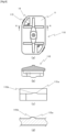
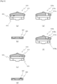
- Fig. 11 (a) is a side cross-sectional view of an adapter 410 according to a fourth variation including a first engagement element 415 that is a protruded portion provided on the lower surface of a base 411, and (b) is a side cross-sectional view (a cross-sectional view along the line B-B in Fig. 5 ) of a brim 423 according to the fourth variation including a second engagement element 427 that is a recessed portion provided in the upper surface of the brim 423.
- each engagement element is preferably arranged at such a position that the timing when resistance is given by the first engagement element during turning the brim of the reservoir container within the gap G can be delayed and attrition caused by sliding of the brim can be minimized.
- reservoir device / 2 pressurized-air supply source / 3: air pipe / 4: nozzle / 10: adapter / 11: base / 12: lateral member / 13: blocking portion / 14: brim-holding claw / 15: first engagement element / 16: through-hole / 17: seal member / 18: joint / 19: window / 20: reservoir container / 21: container body (reservoir cylinder) / 22: flange / 23: brim / 24: inner cylinder / 25: outer cylinder / 26: lower opening / 27: second engagement element/ 28: upper opening / 110, 210, 310, 410, 510: adapter / 115, 215, 315, 415, 515: first engagement element / 327, 427, 527: second engagement element
Landscapes
- Engineering & Computer Science (AREA)
- Mechanical Engineering (AREA)
- Health & Medical Sciences (AREA)
- Life Sciences & Earth Sciences (AREA)
- Public Health (AREA)
- Hydrology & Water Resources (AREA)
- Water Supply & Treatment (AREA)
- Chemical & Material Sciences (AREA)
- Dispersion Chemistry (AREA)
- Anesthesiology (AREA)
- Vascular Medicine (AREA)
- Biomedical Technology (AREA)
- Heart & Thoracic Surgery (AREA)
- Hematology (AREA)
- Animal Behavior & Ethology (AREA)
- General Health & Medical Sciences (AREA)
- Veterinary Medicine (AREA)
- Details Of Rigid Or Semi-Rigid Containers (AREA)
- Closures For Containers (AREA)
- Infusion, Injection, And Reservoir Apparatuses (AREA)
Applications Claiming Priority (2)
| Application Number | Priority Date | Filing Date | Title |
|---|---|---|---|
| JP2022084753 | 2022-05-24 | ||
| PCT/JP2023/018859 WO2023228890A1 (fr) | 2022-05-24 | 2023-05-22 | Adaptateur de récipient de stockage, récipient de stockage et dispositif de stockage |
Publications (1)
| Publication Number | Publication Date |
|---|---|
| EP4534440A1 true EP4534440A1 (fr) | 2025-04-09 |
Family
ID=88919303
Family Applications (1)
| Application Number | Title | Priority Date | Filing Date |
|---|---|---|---|
| EP23811762.6A Pending EP4534440A1 (fr) | 2022-05-24 | 2023-05-22 | Adaptateur de récipient de stockage, récipient de stockage et dispositif de stockage |
Country Status (7)
| Country | Link |
|---|---|
| US (1) | US20250381581A1 (fr) |
| EP (1) | EP4534440A1 (fr) |
| JP (1) | JPWO2023228890A1 (fr) |
| KR (1) | KR20250016084A (fr) |
| CN (1) | CN119255953A (fr) |
| TW (1) | TW202413226A (fr) |
| WO (1) | WO2023228890A1 (fr) |
Family Cites Families (6)
| Publication number | Priority date | Publication date | Assignee | Title |
|---|---|---|---|---|
| JPS4986600U (fr) | 1972-11-20 | 1974-07-26 | ||
| JPS5551433U (fr) | 1978-09-28 | 1980-04-04 | ||
| JP3914951B1 (ja) * | 2006-01-19 | 2007-05-16 | 文雄 田中 | ポンプ及び蓋付き容器 |
| EP2032467B1 (fr) | 2006-06-13 | 2010-08-18 | Nordson Corporation | Seringue de distribution de liquide |
| JP4986600B2 (ja) | 2006-12-20 | 2012-07-25 | 武蔵エンジニアリング株式会社 | 閉蓋具および液体材料貯留容器 |
| JP5916437B2 (ja) * | 2012-02-29 | 2016-05-11 | 三笠産業株式会社 | 封印帯付きキャップ |
-
2023
- 2023-05-22 EP EP23811762.6A patent/EP4534440A1/fr active Pending
- 2023-05-22 TW TW112118875A patent/TW202413226A/zh unknown
- 2023-05-22 JP JP2024523095A patent/JPWO2023228890A1/ja active Pending
- 2023-05-22 CN CN202380042386.XA patent/CN119255953A/zh active Pending
- 2023-05-22 US US18/867,552 patent/US20250381581A1/en active Pending
- 2023-05-22 WO PCT/JP2023/018859 patent/WO2023228890A1/fr not_active Ceased
- 2023-05-22 KR KR1020247033747A patent/KR20250016084A/ko active Pending
Also Published As
| Publication number | Publication date |
|---|---|
| WO2023228890A1 (fr) | 2023-11-30 |
| KR20250016084A (ko) | 2025-02-03 |
| CN119255953A (zh) | 2025-01-03 |
| JPWO2023228890A1 (fr) | 2023-11-30 |
| US20250381581A1 (en) | 2025-12-18 |
| TW202413226A (zh) | 2024-04-01 |
Similar Documents
| Publication | Publication Date | Title |
|---|---|---|
| JP5711884B2 (ja) | プランジャーおよびガスケットの緩み防止機構とその利用 | |
| CN104582742A (zh) | 容器盖的定心辅助件 | |
| CN111746904B (zh) | 储液瓶 | |
| KR101508440B1 (ko) | 뚜껑부착 용기 | |
| BR112015007097B1 (pt) | Processo de montagem de um dispositivo de embalagem para produto cosmético e dispositivo de embalagem para produto cosmético | |
| BR112013012597B1 (pt) | Encerramento de recipiente ventilado | |
| JP2008504956A (ja) | 注射器又はカートリッジ、クロージング・キャップ、及び混合器を含む分配システム | |
| CN102186403A (zh) | 流体容器单元 | |
| EP4534440A1 (fr) | Adaptateur de récipient de stockage, récipient de stockage et dispositif de stockage | |
| CN104972765B (zh) | 用于液体供给单元的保护部件 | |
| US20170102566A1 (en) | Liquid crystal display device and array substrate | |
| US20080300535A1 (en) | Particle cassette, method and kit therefor | |
| JP5869825B2 (ja) | キャップ付きバレル、キャップ、及びプレフィルドシリンジ | |
| US11096863B2 (en) | Port, and medical liquid bag | |
| JPH08112915A (ja) | 液体保持部材の液体流出用開口部に対する保護キャップおよびそれを有する液体保持部材 | |
| JP6275669B2 (ja) | 樹脂製品 | |
| JP2013078442A (ja) | キャップ、キャップ付きバレル、及びプレフィルドシリンジ | |
| WO2017002574A1 (fr) | Contenant distributeur de lingettes humides | |
| JP6655976B2 (ja) | 薬用瓶の樹脂製キャップ | |
| KR102643251B1 (ko) | 롤러 케이스 | |
| WO2014049924A1 (fr) | Support de cartouche, unité de cartouche, et dispositif d'injection de médicament sur lequel est montée l'unité de cartouche | |
| JP4851231B2 (ja) | 樹脂成形品、ダンパー装置および樹脂成形品の製造方法 | |
| HK40117223A (zh) | 储存容器用接头、储存容器及储存装置 | |
| JPH0714209Y2 (ja) | キャップ付き口栓 | |
| JPH0956462A (ja) | 底充填型繰り出し容器 |
Legal Events
| Date | Code | Title | Description |
|---|---|---|---|
| STAA | Information on the status of an ep patent application or granted ep patent |
Free format text: STATUS: THE INTERNATIONAL PUBLICATION HAS BEEN MADE |
|
| PUAI | Public reference made under article 153(3) epc to a published international application that has entered the european phase |
Free format text: ORIGINAL CODE: 0009012 |
|
| STAA | Information on the status of an ep patent application or granted ep patent |
Free format text: STATUS: REQUEST FOR EXAMINATION WAS MADE |
|
| 17P | Request for examination filed |
Effective date: 20241204 |
|
| AK | Designated contracting states |
Kind code of ref document: A1 Designated state(s): AL AT BE BG CH CY CZ DE DK EE ES FI FR GB GR HR HU IE IS IT LI LT LU LV MC ME MK MT NL NO PL PT RO RS SE SI SK SM TR |
|
| DAV | Request for validation of the european patent (deleted) | ||
| DAX | Request for extension of the european patent (deleted) |