EP4534730A2 - Elektrodenstruktur - Google Patents
Elektrodenstruktur Download PDFInfo
- Publication number
- EP4534730A2 EP4534730A2 EP24191394.6A EP24191394A EP4534730A2 EP 4534730 A2 EP4534730 A2 EP 4534730A2 EP 24191394 A EP24191394 A EP 24191394A EP 4534730 A2 EP4534730 A2 EP 4534730A2
- Authority
- EP
- European Patent Office
- Prior art keywords
- catalyst layer
- layer
- outer edge
- catalyst
- porous transport
- Prior art date
- Legal status (The legal status is an assumption and is not a legal conclusion. Google has not performed a legal analysis and makes no representation as to the accuracy of the status listed.)
- Pending
Links
Images


Classifications
-
- C—CHEMISTRY; METALLURGY
- C25—ELECTROLYTIC OR ELECTROPHORETIC PROCESSES; APPARATUS THEREFOR
- C25B—ELECTROLYTIC OR ELECTROPHORETIC PROCESSES FOR THE PRODUCTION OF COMPOUNDS OR NON-METALS; APPARATUS THEREFOR
- C25B9/00—Cells or assemblies of cells; Constructional parts of cells; Assemblies of constructional parts, e.g. electrode-diaphragm assemblies; Process-related cell features
- C25B9/17—Cells comprising dimensionally-stable non-movable electrodes; Assemblies of constructional parts thereof
- C25B9/19—Cells comprising dimensionally-stable non-movable electrodes; Assemblies of constructional parts thereof with diaphragms
- C25B9/23—Cells comprising dimensionally-stable non-movable electrodes; Assemblies of constructional parts thereof with diaphragms comprising ion-exchange membranes in or on which electrode material is embedded
-
- H—ELECTRICITY
- H01—ELECTRIC ELEMENTS
- H01M—PROCESSES OR MEANS, e.g. BATTERIES, FOR THE DIRECT CONVERSION OF CHEMICAL ENERGY INTO ELECTRICAL ENERGY
- H01M4/00—Electrodes
- H01M4/86—Inert electrodes with catalytic activity, e.g. for fuel cells
- H01M4/8605—Porous electrodes
-
- C—CHEMISTRY; METALLURGY
- C25—ELECTROLYTIC OR ELECTROPHORETIC PROCESSES; APPARATUS THEREFOR
- C25B—ELECTROLYTIC OR ELECTROPHORETIC PROCESSES FOR THE PRODUCTION OF COMPOUNDS OR NON-METALS; APPARATUS THEREFOR
- C25B11/00—Electrodes; Manufacture thereof not otherwise provided for
- C25B11/02—Electrodes; Manufacture thereof not otherwise provided for characterised by shape or form
- C25B11/03—Electrodes; Manufacture thereof not otherwise provided for characterised by shape or form perforated or foraminous
- C25B11/031—Porous electrodes
- C25B11/032—Gas diffusion electrodes
-
- C—CHEMISTRY; METALLURGY
- C25—ELECTROLYTIC OR ELECTROPHORETIC PROCESSES; APPARATUS THEREFOR
- C25B—ELECTROLYTIC OR ELECTROPHORETIC PROCESSES FOR THE PRODUCTION OF COMPOUNDS OR NON-METALS; APPARATUS THEREFOR
- C25B11/00—Electrodes; Manufacture thereof not otherwise provided for
- C25B11/04—Electrodes; Manufacture thereof not otherwise provided for characterised by the material
- C25B11/051—Electrodes formed of electrocatalysts on a substrate or carrier
- C25B11/052—Electrodes comprising one or more electrocatalytic coatings on a substrate
-
- C—CHEMISTRY; METALLURGY
- C25—ELECTROLYTIC OR ELECTROPHORETIC PROCESSES; APPARATUS THEREFOR
- C25B—ELECTROLYTIC OR ELECTROPHORETIC PROCESSES FOR THE PRODUCTION OF COMPOUNDS OR NON-METALS; APPARATUS THEREFOR
- C25B11/00—Electrodes; Manufacture thereof not otherwise provided for
- C25B11/04—Electrodes; Manufacture thereof not otherwise provided for characterised by the material
- C25B11/051—Electrodes formed of electrocatalysts on a substrate or carrier
- C25B11/073—Electrodes formed of electrocatalysts on a substrate or carrier characterised by the electrocatalyst material
- C25B11/075—Electrodes formed of electrocatalysts on a substrate or carrier characterised by the electrocatalyst material consisting of a single catalytic element or catalytic compound
- C25B11/081—Electrodes formed of electrocatalysts on a substrate or carrier characterised by the electrocatalyst material consisting of a single catalytic element or catalytic compound the element being a noble metal
-
- C—CHEMISTRY; METALLURGY
- C25—ELECTROLYTIC OR ELECTROPHORETIC PROCESSES; APPARATUS THEREFOR
- C25B—ELECTROLYTIC OR ELECTROPHORETIC PROCESSES FOR THE PRODUCTION OF COMPOUNDS OR NON-METALS; APPARATUS THEREFOR
- C25B13/00—Diaphragms; Spacing elements
- C25B13/04—Diaphragms; Spacing elements characterised by the material
- C25B13/08—Diaphragms; Spacing elements characterised by the material based on organic materials
-
- C—CHEMISTRY; METALLURGY
- C25—ELECTROLYTIC OR ELECTROPHORETIC PROCESSES; APPARATUS THEREFOR
- C25B—ELECTROLYTIC OR ELECTROPHORETIC PROCESSES FOR THE PRODUCTION OF COMPOUNDS OR NON-METALS; APPARATUS THEREFOR
- C25B9/00—Cells or assemblies of cells; Constructional parts of cells; Assemblies of constructional parts, e.g. electrode-diaphragm assemblies; Process-related cell features
- C25B9/60—Constructional parts of cells
-
- C—CHEMISTRY; METALLURGY
- C25—ELECTROLYTIC OR ELECTROPHORETIC PROCESSES; APPARATUS THEREFOR
- C25B—ELECTROLYTIC OR ELECTROPHORETIC PROCESSES FOR THE PRODUCTION OF COMPOUNDS OR NON-METALS; APPARATUS THEREFOR
- C25B9/00—Cells or assemblies of cells; Constructional parts of cells; Assemblies of constructional parts, e.g. electrode-diaphragm assemblies; Process-related cell features
- C25B9/70—Assemblies comprising two or more cells
- C25B9/73—Assemblies comprising two or more cells of the filter-press type
- C25B9/75—Assemblies comprising two or more cells of the filter-press type having bipolar electrodes
-
- C—CHEMISTRY; METALLURGY
- C25—ELECTROLYTIC OR ELECTROPHORETIC PROCESSES; APPARATUS THEREFOR
- C25B—ELECTROLYTIC OR ELECTROPHORETIC PROCESSES FOR THE PRODUCTION OF COMPOUNDS OR NON-METALS; APPARATUS THEREFOR
- C25B9/00—Cells or assemblies of cells; Constructional parts of cells; Assemblies of constructional parts, e.g. electrode-diaphragm assemblies; Process-related cell features
- C25B9/70—Assemblies comprising two or more cells
- C25B9/73—Assemblies comprising two or more cells of the filter-press type
- C25B9/77—Assemblies comprising two or more cells of the filter-press type having diaphragms
-
- H—ELECTRICITY
- H01—ELECTRIC ELEMENTS
- H01M—PROCESSES OR MEANS, e.g. BATTERIES, FOR THE DIRECT CONVERSION OF CHEMICAL ENERGY INTO ELECTRICAL ENERGY
- H01M4/00—Electrodes
- H01M4/86—Inert electrodes with catalytic activity, e.g. for fuel cells
- H01M4/8636—Inert electrodes with catalytic activity, e.g. for fuel cells with a gradient in another property than porosity
- H01M4/8642—Gradient in composition
-
- H—ELECTRICITY
- H01—ELECTRIC ELEMENTS
- H01M—PROCESSES OR MEANS, e.g. BATTERIES, FOR THE DIRECT CONVERSION OF CHEMICAL ENERGY INTO ELECTRICAL ENERGY
- H01M4/00—Electrodes
- H01M4/86—Inert electrodes with catalytic activity, e.g. for fuel cells
- H01M4/88—Processes of manufacture
- H01M4/8803—Supports for the deposition of the catalytic active composition
- H01M4/881—Electrolytic membranes
-
- H—ELECTRICITY
- H01—ELECTRIC ELEMENTS
- H01M—PROCESSES OR MEANS, e.g. BATTERIES, FOR THE DIRECT CONVERSION OF CHEMICAL ENERGY INTO ELECTRICAL ENERGY
- H01M8/00—Fuel cells; Manufacture thereof
- H01M8/02—Details
- H01M8/0202—Collectors; Separators, e.g. bipolar separators; Interconnectors
- H01M8/023—Porous and characterised by the material
- H01M8/0241—Composites
- H01M8/0245—Composites in the form of layered or coated products
-
- H—ELECTRICITY
- H01—ELECTRIC ELEMENTS
- H01M—PROCESSES OR MEANS, e.g. BATTERIES, FOR THE DIRECT CONVERSION OF CHEMICAL ENERGY INTO ELECTRICAL ENERGY
- H01M8/00—Fuel cells; Manufacture thereof
- H01M8/10—Fuel cells with solid electrolytes
- H01M8/1004—Fuel cells with solid electrolytes characterised by membrane-electrode assemblies [MEA]
-
- C—CHEMISTRY; METALLURGY
- C25—ELECTROLYTIC OR ELECTROPHORETIC PROCESSES; APPARATUS THEREFOR
- C25B—ELECTROLYTIC OR ELECTROPHORETIC PROCESSES FOR THE PRODUCTION OF COMPOUNDS OR NON-METALS; APPARATUS THEREFOR
- C25B1/00—Electrolytic production of inorganic compounds or non-metals
- C25B1/01—Products
- C25B1/02—Hydrogen or oxygen
- C25B1/04—Hydrogen or oxygen by electrolysis of water
-
- H—ELECTRICITY
- H01—ELECTRIC ELEMENTS
- H01M—PROCESSES OR MEANS, e.g. BATTERIES, FOR THE DIRECT CONVERSION OF CHEMICAL ENERGY INTO ELECTRICAL ENERGY
- H01M8/00—Fuel cells; Manufacture thereof
- H01M8/10—Fuel cells with solid electrolytes
- H01M2008/1095—Fuel cells with polymeric electrolytes
-
- Y—GENERAL TAGGING OF NEW TECHNOLOGICAL DEVELOPMENTS; GENERAL TAGGING OF CROSS-SECTIONAL TECHNOLOGIES SPANNING OVER SEVERAL SECTIONS OF THE IPC; TECHNICAL SUBJECTS COVERED BY FORMER USPC CROSS-REFERENCE ART COLLECTIONS [XRACs] AND DIGESTS
- Y02—TECHNOLOGIES OR APPLICATIONS FOR MITIGATION OR ADAPTATION AGAINST CLIMATE CHANGE
- Y02E—REDUCTION OF GREENHOUSE GAS [GHG] EMISSIONS, RELATED TO ENERGY GENERATION, TRANSMISSION OR DISTRIBUTION
- Y02E60/00—Enabling technologies; Technologies with a potential or indirect contribution to GHG emissions mitigation
- Y02E60/30—Hydrogen technology
- Y02E60/50—Fuel cells
Definitions
- the present invention relates to an electrode structure.
- H 2 hydrogen
- H 2 O water
- the solid polymer water electrolyzer has a cell stack with cells and separators stacked alternately. Each of the cells includes an electrolyte membrane, and a catalyst layer formed on each of both sides of the electrolyte membrane.
- the conventional solid polymer water electrolyzer is described in Japanese Patent Application Laid-Open No. 2022-023996 , for example.
- the catalyst layer is entirely used as an electrode.
- a formation range of the catalyst layer relative to the electrolyte membrane is determined with low accuracy, using the catalyst layer entirely as an electrode causes fluctuation of an effective region to practically function as an electrode.
- the present invention is intended to provide a technique that achieves reduction in fluctuation of an effective region to function as an electrode even if a formation range of a catalyst layer is determined with low accuracy.
- the present invention is intended for an electrode structure comprising: an electrolyte membrane; a first catalyst layer formed on one of surfaces of the electrolyte membrane; a first gas diffusion layer stacked on a surface of the first catalyst layer; a second catalyst layer formed on the other surface of the electrolyte membrane; and a porous transport layer stacked on a surface of the second catalyst layer.
- An outer edge of the porous transport layer is arranged at a more inward position than an outer edge of the first gas diffusion layer, an outer edge of the first catalyst layer, and an outer edge of the second catalyst layer.
- an effective region of the first catalyst layer and the second catalyst layer is defined using the porous transport layer.
- the first catalyst layer and the second catalyst layer may have an overlapping region where the first catalyst layer and the second catalyst layer overlap each other and the outer edge of the first catalyst layer and the outer edge of the second catalyst layer may be at positions differing from each other, and the outer edge of the porous transport layer may be arranged at a more inward position than an outer edge of the overlapping region.
- the porous transport layer may have a rectangular shape and all the four sides of the porous transport layer may be arranged at more inward positions than the outer edge of the first gas diffusion layer, the outer edge of the first catalyst layer, and the outer edge of the second catalyst layer.
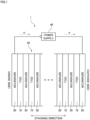
- Fig. 1 is a schematic view of a water electrolyzer 1.
- the water electrolyzer 1 is to produce hydrogen by solid polymer water electrolysis.
- the water electrolyzer 1 includes a cell stack 30 with a plurality of cells 10 and a plurality of separators 20, and a power supply 40.
- the cells 10 and the separators 20 are stacked alternately to form the cell stack 30.
- a direction in which the cells 10 and the separators 20 are stacked will be called a "stacking direction.”
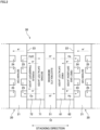
- Fig. 2 schematically shows only one cell 10 and separators 20 in a pair arranged on both sides of this cell 10 that form the cell stack 30 of the water electrolyzer 1.
- one cell 10 includes an electrolyte membrane 51, a first catalyst layer 61, a first gas diffusion layer 62, a second catalyst layer 71, and a porous transport layer 72.
- a stacked body composed of the electrolyte membrane 51, the first catalyst layer 61, the first gas diffusion layer 62, the second catalyst layer 71, and the porous transport layer 72 is called a membrane-electrode-assembly (EMA).
- EMA membrane-electrode-assembly
- a stacked body composed of the electrolyte membrane 51, the first catalyst layer 61, and the second catalyst layer 71 is called a catalyst-coated membrane (CCM).
- the electrolyte membrane 51 is a membrane having ion conductivity (ionexchange membrane).
- the electrolyte membrane 51 of the present preferred embodiment is a proton-exchange membrane that conducts hydrogen ions (H + ).
- a fluorine-based or hydrocarbon-based polymer electrolyte membrane is used as the electrolyte membrane 51. More specifically, a polymer electrolyte membrane containing perfluorocarbon sulfonic acid is used as the electrolyte membrane 51, for example.
- the electrolyte membrane 51 has a thickness from 5 to 200 ⁇ m, for example.
- the first catalyst layer 61 is a catalyst layer that causes electrochemical reaction on a cathode side.
- the first catalyst layer 61 is formed on a cathode-side surface of the electrolyte membrane 51.
- the first catalyst layer 61 contains a large number of carbon particles on which catalyst particles are supported.
- the catalyst particles are particles of platinum, for example. Alternatively, the catalyst particles may be prepared by mixing particles of a tiny amount of ruthenium or cobalt into particles of platinum.
- hydrogen ions (H + ) and electrons (e - ) are supplied to the first catalyst layer 61.
- the power supply 40 applies a voltage between the first catalyst layer 61 and the second catalyst layer 71. By doing so, by the actions of the applied voltage and the catalyst particles, a reduction reaction is caused in the first catalyst layer 61 to generate hydrogen gas (H 2 ) from the hydrogen ions and the electrons.
- the first gas diffusion layer 62 is a layer for transporting electrons from the separator 20 to the first catalyst layer 61 and for transporting hydrogen generated in the first catalyst layer 61 to the separator 20.
- the first gas diffusion layer 62 is stacked on an external surface of the first catalyst layer 61 (a surface on the opposite side to the electrolyte membrane 51).
- the first catalyst layer 61 is interposed between the electrolyte membrane 51 and the first gas diffusion layer 62.
- the first gas diffusion layer 62 is made of a material having electrical conductivity and porosity.
- the first gas diffusion layer 62 is formed using a porous base material (carbon paper) made of carbon, for example.
- the second catalyst layer 71 is a catalyst layer that causes electrochemical reaction on an anode side.
- the second catalyst layer 71 is formed on an anode-side surface of the electrolyte membrane 51 (a surface on the opposite side to the first catalyst layer 61).
- the second catalyst layer 71 contains a large number of catalyst particles.
- the catalyst particles are particles of iridium oxide (IrOx), platinum (Pt), an alloy of iridium (Ir) and ruthenium (Ru), or an alloy of iridium (Ir) and titanium dioxide (TiO 2 ), for example.
- water (H 2 O) is supplied to the second catalyst layer 71.
- the power supply 40 applies a voltage between the first catalyst layer 61 and the second catalyst layer 71.
- the water is electrolyzed into hydrogen ions (H + ), oxygen (O 2 ), and electrons (e - ) in the second catalyst layer 71.
- the porous transport layer 72 is a layer for supplying water uniformly to the second catalyst layer 71 and for transporting oxygen and electrons generated in the second catalyst layer 71 to the separator 20.
- the porous transport layer 72 is stacked on an external surface of the second catalyst layer 71 (a surface on the opposite side to the electrolyte membrane 51).
- the second catalyst layer 71 is interposed between the electrolyte membrane 51 and the porous transport layer 72.
- the porous transport layer 72 is made of a material having electrical conductivity and porosity.
- the porous transport layer 72 is formed using a porous base material made of metal such as titanium or stainless steel, for example.
- the separator 20 is a layer for moving electrons between the cells 10 next to each other and for forming a passage for water, oxygen, and hydrogen.
- the separator 20 is interposed between the first gas diffusion layer 62 of one cell 10 and the porous transport layer 72 of the cell 10 next to the one cell 10.
- the separator 20 is composed of a metal plate 21 having electrical conductivity and impermeable to gas and liquid.
- the metal plate 21 has a cathode surface 22 contacting the first gas diffusion layer 62, and an anode surface 23 contacting the porous transport layer 72.
- the metal plate 21 has a plurality of anode grooves 25 formed at the anode surface 23. Water is supplied to the porous transport layer 72 through the anode grooves 25 of the separator 20. Oxygen generated in the second catalyst layer 71 passes through the porous transport layer 72 and is then output to the outside through the anode grooves 25 of the separator 20.
- water is supplied from the anode grooves 25 of the separator 20 to the second catalyst layer 71 through the porous transport layer 72. Then, by the actions of a voltage applied from the power supply 40 and the catalyst particles in the second catalyst layer 71, the water is decomposed into hydrogen ions, oxygen, and electrons.
- the hydrogen ions propagate through the electrolyte membrane 51 into the first catalyst layer 61.
- the oxygen passes through the porous transport layer 72 and the anode grooves 25 of the separator 20 and is then output to the outside.
- the electrons pass through the porous transport layer 72 and the separator 20 and then flow into the adjoining cell 10. In the adjoining cell 10, these electrons pass through the first gas diffusion layer 62 to reach the first catalyst layer 61.
- the hydrogen ions and the electrons are combined with each other to generate hydrogen in the first catalyst layer 61.
- the generated hydrogen passes through the first gas diffusion layer 62 and the cathode grooves 24 of the separator 20 and is then output to the outside. In this way, hydrogen is produced.
- the cell 10 is an "electrode structure" having a function as an electrode.
- the configuration of the cell 10 will be described below in more detail.
- Fig. 3 shows one cell 10 viewed in the stacking direction from the anode side.
- Fig. 4 is a sectional view of the cell 10.
- Each of the electrolyte membrane 51, the first catalyst layer 61, the first gas diffusion layer 62, the second catalyst layer 71, and the porous transport layer 72 has a rectangular shape in a state viewed in the stacking direction.
- an outer edge of the first catalyst layer 61 is arranged at a more inward position than an outer edge of the electrolyte membrane 51.
- the area of the first catalyst layer 61 is smaller than that of the electrolyte membrane 51.
- an outer edge of the second catalyst layer 71 is arranged at a more inward position than the outer edge of the electrolyte membrane 51.
- the area of the second catalyst layer 71 is smaller than that of the electrolyte membrane 51.
- the outer edge of the porous transport layer 72 is arranged at a more inward position than an outer edge of the overlapping region 90 where the first catalyst layer 61 and the second catalyst layer 71 overlap each other.
- the porous transport layer 72 has a rectangular shape in a state viewed in the stacking direction. Furthermore, all the four sides of the outer edge of the porous transport layer 72 are arranged at more inward positions than the outer edge of the first gas diffusion layer 62, the outer edge of the first catalyst layer 61, and the outer edge of the second catalyst layer 71. Thus, it is possible to define the rectangular effective region A of the first catalyst layer 61 and the second catalyst layer 71 with high accuracy using the porous transport layer 72.
- all the four sides of the rectangular porous transport layer 72 are arranged at more inward positions than the outer edge of the first gas diffusion layer 62, the outer edge of the first catalyst layer 61, and the outer edge of the second catalyst layer 71.
- only some of the four sides of the porous transport layer 72 may be arranged at more inward positions than the outer edge of the first gas diffusion layer 62, the outer edge of the first catalyst layer 61, and the outer edge of the second catalyst layer 71.
- the two long sides and the two short sides of the porous transport layer 72 shown in Fig. 3 only the two long sides or only the two short sides may be arranged at more inward positions than the outer edge of the first gas diffusion layer 62, the outer edge of the first catalyst layer 61, and the outer edge of the second catalyst layer 71.
- the cell 10 discussed in the above-described preferred embodiment uses a proton-exchange membrane as the electrolyte membrane 51.
- the electrode structure of the present invention may use an anion-exchange membrane as an electrolyte membrane.
Landscapes
- Chemical & Material Sciences (AREA)
- Chemical Kinetics & Catalysis (AREA)
- Electrochemistry (AREA)
- Engineering & Computer Science (AREA)
- Materials Engineering (AREA)
- Organic Chemistry (AREA)
- Metallurgy (AREA)
- General Chemical & Material Sciences (AREA)
- Manufacturing & Machinery (AREA)
- Sustainable Development (AREA)
- Sustainable Energy (AREA)
- Life Sciences & Earth Sciences (AREA)
- Composite Materials (AREA)
- Inorganic Chemistry (AREA)
- Electrolytic Production Of Non-Metals, Compounds, Apparatuses Therefor (AREA)
- Fuel Cell (AREA)
- Inert Electrodes (AREA)
- Electrodes For Compound Or Non-Metal Manufacture (AREA)
Applications Claiming Priority (1)
| Application Number | Priority Date | Filing Date | Title |
|---|---|---|---|
| JP2023155640A JP2025047251A (ja) | 2023-09-21 | 2023-09-21 | 電極構造体 |
Publications (2)
| Publication Number | Publication Date |
|---|---|
| EP4534730A2 true EP4534730A2 (de) | 2025-04-09 |
| EP4534730A3 EP4534730A3 (de) | 2025-04-30 |
Family
ID=92108379
Family Applications (1)
| Application Number | Title | Priority Date | Filing Date |
|---|---|---|---|
| EP24191394.6A Pending EP4534730A3 (de) | 2023-09-21 | 2024-07-29 | Elektrodenstruktur |
Country Status (5)
| Country | Link |
|---|---|
| US (1) | US20250101611A1 (de) |
| EP (1) | EP4534730A3 (de) |
| JP (1) | JP2025047251A (de) |
| CN (1) | CN119663327A (de) |
| AU (1) | AU2024205773B2 (de) |
Citations (1)
| Publication number | Priority date | Publication date | Assignee | Title |
|---|---|---|---|---|
| JP2022023996A (ja) | 2021-11-05 | 2022-02-08 | 東京瓦斯株式会社 | 電気化学デバイス |
Family Cites Families (4)
| Publication number | Priority date | Publication date | Assignee | Title |
|---|---|---|---|---|
| JP5681792B2 (ja) * | 2011-04-01 | 2015-03-11 | 本田技研工業株式会社 | 燃料電池用電解質膜・電極構造体及びその製造方法 |
| JP6158758B2 (ja) * | 2014-06-30 | 2017-07-05 | 本田技研工業株式会社 | 燃料電池用樹脂枠付き電解質膜・電極構造体 |
| JP6659770B2 (ja) * | 2018-06-08 | 2020-03-04 | 本田技研工業株式会社 | 燃料電池スタック |
| JP6715277B2 (ja) * | 2018-03-15 | 2020-07-01 | 本田技研工業株式会社 | 燃料電池スタック及び燃料電池スタック用ダミーセル |
-
2023
- 2023-09-21 JP JP2023155640A patent/JP2025047251A/ja active Pending
-
2024
- 2024-07-29 EP EP24191394.6A patent/EP4534730A3/de active Pending
- 2024-08-15 AU AU2024205773A patent/AU2024205773B2/en active Active
- 2024-09-17 US US18/887,453 patent/US20250101611A1/en active Pending
- 2024-09-18 CN CN202411299447.3A patent/CN119663327A/zh active Pending
Patent Citations (1)
| Publication number | Priority date | Publication date | Assignee | Title |
|---|---|---|---|---|
| JP2022023996A (ja) | 2021-11-05 | 2022-02-08 | 東京瓦斯株式会社 | 電気化学デバイス |
Also Published As
| Publication number | Publication date |
|---|---|
| EP4534730A3 (de) | 2025-04-30 |
| JP2025047251A (ja) | 2025-04-03 |
| CN119663327A (zh) | 2025-03-21 |
| AU2024205773A1 (en) | 2025-04-10 |
| US20250101611A1 (en) | 2025-03-27 |
| AU2024205773B2 (en) | 2025-12-18 |
Similar Documents
| Publication | Publication Date | Title |
|---|---|---|
| EP2612390B1 (de) | Anordnung für eine umkehrbare brennstoffzelle | |
| KR20040099149A (ko) | 연료 전지 | |
| US7951284B2 (en) | Electrolysis apparatus, electrochemical reaction membrane apparatus, porous electrical conductor, and production method thereof | |
| US20240093383A1 (en) | Water electrolyzer | |
| EP4343031A2 (de) | Separator und wasserelektrolyseur | |
| US7572538B2 (en) | Fuel cell | |
| CN116334668A (zh) | 膜电极接合体及膜电极接合体的制造方法 | |
| EP4534730A2 (de) | Elektrodenstruktur | |
| KR20140133301A (ko) | 전기화학셀용 막전극 접합체 | |
| US20240110299A1 (en) | Support, electrode, membrane electrode assembly, electrochemical cell, stack, and electrolyzer | |
| US20250101612A1 (en) | Electrode structure | |
| US20250101610A1 (en) | Electrode structure | |
| US20230250543A1 (en) | Catalyst layer, membrane electrode assembly | |
| EP4435146A2 (de) | Elektrodenstruktur und wasserelektrolyseur | |
| US20240318331A1 (en) | Electrode structure and water electrolyzer | |
| JP2006185882A (ja) | 金属製セパレータを用いた燃料電池の運転方法、および金属製セパレータを用いた燃料電池を有する発電装置 | |
| JP7057731B2 (ja) | 燃料電池および燃料電池の製造方法 |
Legal Events
| Date | Code | Title | Description |
|---|---|---|---|
| PUAI | Public reference made under article 153(3) epc to a published international application that has entered the european phase |
Free format text: ORIGINAL CODE: 0009012 |
|
| STAA | Information on the status of an ep patent application or granted ep patent |
Free format text: STATUS: THE APPLICATION HAS BEEN PUBLISHED |
|
| PUAL | Search report despatched |
Free format text: ORIGINAL CODE: 0009013 |
|
| AK | Designated contracting states |
Kind code of ref document: A2 Designated state(s): AL AT BE BG CH CY CZ DE DK EE ES FI FR GB GR HR HU IE IS IT LI LT LU LV MC ME MK MT NL NO PL PT RO RS SE SI SK SM TR |
|
| AK | Designated contracting states |
Kind code of ref document: A3 Designated state(s): AL AT BE BG CH CY CZ DE DK EE ES FI FR GB GR HR HU IE IS IT LI LT LU LV MC ME MK MT NL NO PL PT RO RS SE SI SK SM TR |
|
| RIC1 | Information provided on ipc code assigned before grant |
Ipc: H01M 8/1004 20160101ALI20250327BHEP Ipc: H01M 4/88 20060101ALI20250327BHEP Ipc: H01M 4/86 20060101ALI20250327BHEP Ipc: C25B 13/00 20060101ALI20250327BHEP Ipc: C25B 11/03 20210101ALI20250327BHEP Ipc: C25B 1/04 20210101AFI20250327BHEP |
|
| STAA | Information on the status of an ep patent application or granted ep patent |
Free format text: STATUS: REQUEST FOR EXAMINATION WAS MADE |
|
| 17P | Request for examination filed |
Effective date: 20251014 |
|
| GRAP | Despatch of communication of intention to grant a patent |
Free format text: ORIGINAL CODE: EPIDOSNIGR1 |
|
| STAA | Information on the status of an ep patent application or granted ep patent |
Free format text: STATUS: GRANT OF PATENT IS INTENDED |
|
| RIC1 | Information provided on ipc code assigned before grant |
Ipc: C25B 1/04 20210101AFI20260126BHEP Ipc: H01M 4/86 20060101ALI20260126BHEP Ipc: H01M 4/88 20060101ALI20260126BHEP Ipc: H01M 8/1004 20160101ALI20260126BHEP Ipc: C25B 9/60 20210101ALI20260126BHEP Ipc: C25B 9/75 20210101ALI20260126BHEP Ipc: C25B 9/77 20210101ALI20260126BHEP Ipc: H01M 8/0245 20160101ALI20260126BHEP |
|
| INTG | Intention to grant announced |
Effective date: 20260206 |