EP4534793A1 - Ensemble porte ou fenêtre - Google Patents
Ensemble porte ou fenêtre Download PDFInfo
- Publication number
- EP4534793A1 EP4534793A1 EP23202137.8A EP23202137A EP4534793A1 EP 4534793 A1 EP4534793 A1 EP 4534793A1 EP 23202137 A EP23202137 A EP 23202137A EP 4534793 A1 EP4534793 A1 EP 4534793A1
- Authority
- EP
- European Patent Office
- Prior art keywords
- sash
- section
- end cap
- threshold
- door
- Prior art date
- Legal status (The legal status is an assumption and is not a legal conclusion. Google has not performed a legal analysis and makes no representation as to the accuracy of the status listed.)
- Granted
Links
Images


Classifications
-
- E—FIXED CONSTRUCTIONS
- E06—DOORS, WINDOWS, SHUTTERS, OR ROLLER BLINDS IN GENERAL; LADDERS
- E06B—FIXED OR MOVABLE CLOSURES FOR OPENINGS IN BUILDINGS, VEHICLES, FENCES OR LIKE ENCLOSURES IN GENERAL, e.g. DOORS, WINDOWS, BLINDS, GATES
- E06B7/00—Special arrangements or measures in connection with doors or windows
- E06B7/16—Sealing arrangements on wings or parts co-operating with the wings
- E06B7/22—Sealing arrangements on wings or parts co-operating with the wings by means of elastic edgings, e.g. elastic rubber tubes; by means of resilient edgings, e.g. felt or plush strips, resilient metal strips
- E06B7/23—Plastic, sponge rubber, or like strips or tubes
- E06B7/2316—Plastic, sponge rubber, or like strips or tubes used as a seal between the floor and the wing
-
- E—FIXED CONSTRUCTIONS
- E06—DOORS, WINDOWS, SHUTTERS, OR ROLLER BLINDS IN GENERAL; LADDERS
- E06B—FIXED OR MOVABLE CLOSURES FOR OPENINGS IN BUILDINGS, VEHICLES, FENCES OR LIKE ENCLOSURES IN GENERAL, e.g. DOORS, WINDOWS, BLINDS, GATES
- E06B1/00—Border constructions of openings in walls, floors, or ceilings; Frames to be rigidly mounted in such openings
- E06B1/70—Sills; Thresholds
-
- E—FIXED CONSTRUCTIONS
- E06—DOORS, WINDOWS, SHUTTERS, OR ROLLER BLINDS IN GENERAL; LADDERS
- E06B—FIXED OR MOVABLE CLOSURES FOR OPENINGS IN BUILDINGS, VEHICLES, FENCES OR LIKE ENCLOSURES IN GENERAL, e.g. DOORS, WINDOWS, BLINDS, GATES
- E06B7/00—Special arrangements or measures in connection with doors or windows
- E06B7/26—Rain or draught deflectors, e.g. under sliding wings also protection against light for doors
Definitions
- the invention relates to a door or window arrangement having the features of the preamble of claim 1. Furthermore, the invention relates to a building closure having the features of the independent claim.
- Door or window assemblies of the type mentioned above, with, for example, a sash that opens outward relative to the frame, are known from the prior art.
- Such door or window assemblies have a shoulder on the frame side of the lower frame cross member, against which the sash, with a sash overlap formed on the underside of the sash, rests sealingly in the closed position.
- the sash typically has lateral sash overlaps on the sash sides and a sash overlap on the sash top, which allow the sash to seal tightly against the frame when closed, a circumferential seal is implemented between the sash and the frame (circumferential sealing layer).
- the threshold represents a tripping hazard or an obstacle, particularly for people with physical disabilities such as wheelchair users or seniors with walking frames.
- the invention is based on the object of providing an improved door or window arrangement. It is desirable to improve accessibility and ensure sufficient tightness at a reasonable cost.
- the invention solves this problem by a door or window arrangement having the features of claim 1.
- the door or window arrangement comprises a frame and a sash mounted on the frame and pivotable relative to the frame, preferably towards an outside, between an open position and a closed position (possibly an outward-opening sash or outward-opening door).
- the sash has lateral sash overlaps, each of which has an overlap seal attached to it for sealing with the frame or with vertical frame members (when the sash is closed).
- the sash can also have a sash overlap on its upper side with an attached overlap seal for sealing it with the frame or with an upper frame cross member. On its underside, however, the sash is designed without an overlap (no sash overlap on the underside of the sash).
- the frame has a lower frame cross member extending along a longitudinal direction, wherein a threshold with a threshold surface, in particular a tread surface, is arranged on the lower frame cross member towards the outside.
- An end cap is attached to one or both ends of the weatherboard.
- the end cap has a downwardly projecting section (along the direction of gravity) with a threshold contact surface, by means of which the The section projecting downwards rests sealingly on the sill surface when the sash is in the closed position.
- a receptacle On or in the end cap, in particular in a base section of the end cap, a receptacle is formed which has a cross-section complementary to the seal of the weather strip and sealingly receives an end section of the seal.
- the proposed design improves accessibility, particularly for sashes that open outwards relative to the frame (outward-opening doors), as a sash overlap on the underside of the sash and a corresponding stop raised from the floor are no longer required.
- the end cap attached to the front of the weatherboard seals off the interfaces crucial for sealing, namely the threshold surface of the sill, the overlap seal on the side sash overlap, and The elastic seal in the weatherboard is sealed together when the sash is closed. This ensures adequate sealing on the underside of the sash.
- side sash overlaps and a sash overlap on the top of the sash, each with its own overlap seal a continuous sealing layer can be achieved between the sash and frame.
- the end cap can have a base portion, in particular a substantially cuboidal one, in which the receptacle for the seal is formed and/or from which the lateral portion of the end cap extends. This contributes to a comparatively stable design of the end cap, since the various portions of the end cap are connected by means of the base portion.
- a fastening section can extend from the base section, by means of which the end cap is fastened to the (relevant) front end of the weatherboard, preferably by means of a screw. This contributes to a stable fastening of the end cap to the weatherboard.
- a passage for a screw (fastening screw) for fastening the fastening section to the weatherboard is formed in the fastening section. The passage can be chamfered or countersunk on the outer side of the fastening section (weather side) for sealing with the screw head, in particular a countersunk head.
- a groove is formed for sealingly accommodating a front end section of the weatherboard.
- the fastening section extends, in particular, transversely to the above-mentioned direction of extension from the base section of the end cap.
- a coupling section can extend from the base section along or parallel to the direction of extension, penetrating into a corresponding pocket on the weatherboard.
- the pocket is formed on a web of the weatherboard that engages under the sash on its underside. This stabilizes the coupling of the end cap and weatherboard and contributes to a good seal.
- a groove extending along or parallel to the direction of extension can be formed on the web of the weatherboard that engages under the sash for securing the weatherboard seal.
- the base section can be fixed at its (upwardly oriented along the direction of gravity)
- the top surface has a contact surface through which the base section contacts the wing on its underside, or in other words, is in contact with the underside of the wing. This achieves improved sealing and increased stability between the end cap and the wing.
- the threshold can have a gradient towards the outside, wherein the threshold contact surface of the downwardly projecting section of the end cap is adapted to the gradient of the threshold.
- the threshold contact surface is adapted to the gradient of the threshold in such a way that, when the sash is in the closed position, the threshold contact surface rests evenly and sealingly on the threshold surface.
- the outward gradient of the threshold can compensate for a height difference between a floor covering on the outside and the lower frame cross member or the highest point of the lower frame cross member. This improves accessibility.
- a water drainage direction is also specified.
- the threshold contact surface of the downwardly projecting section and the threshold surface of the threshold can be oriented parallel to one another when the sash is in the closed position.
- the seal can be spaced at one or both of its front ends from the overlap seal of the respective lateral wing overlap, with a section of the end cap, in particular the base section of the end cap, being arranged at this spacing.
- the seal deliberately ends at one or both front ends at a distance from the respective overlap seal, creating space for a section of the end cap.
- the end cap can thus connect the various interfaces and exert its sealing effect.
- the end cap can be made of a single piece and/or made of elastic soft plastic. This contributes to a stable design and a sufficiently good sealing effect.
- the building closure is designed and/or intended to separate the inside of a building from its surroundings (outside or outside of the building).
- the building closure has a door or window arrangement with one or more of the aspects described above.
- the building closure has an inside covering (inside floor covering) adjacent to the lower frame cross member and an outside covering (outside floor covering) adjacent to the lower frame cross member and the sill.
- the height difference (h) along the direction of gravity between the highest point of the sill and the lower frame cross member relative to the inside covering and the outside covering is more than 0 mm (millimeters) and a maximum of 20 mm (0 ⁇ h ⁇ 20 mm), preferably more than 5 mm and a maximum of 15 mm (5 ⁇ h ⁇ 15 mm).
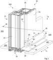
- Figure 1 shows a section of a building enclosure, which is designated overall by the reference numeral 100.
- the building enclosure 100 is designed and intended to separate a building interior 102 from the exterior or surroundings 104 (building exterior).
- the building closure 100 comprises a door or window arrangement 10, which in turn comprises a lower frame cross member 26 with a threshold 28 arranged thereon and which will be described in more detail below.
- the building closure 100 has an inner covering 106 adjacent to the lower frame cross member 26 and an outer covering 108 adjacent to the lower frame cross member 26 and the threshold 28.
- the height difference h along the direction of gravity g between the highest point of the threshold 28 and the lower frame cross member 26 relative to the inner covering 106 and the outer covering 108 is more than 0 mm (millimeters) and a maximum of 20 mm (0 ⁇ h ⁇ 20 mm; cf. Fig.3 ).
- the inner lining 106 is arranged higher than the outer lining 108, contrary to the direction of gravity g.
- the door or window arrangement 10 has a frame 12 (only partially shown) and a sash 16 mounted on the frame 12 and pivotable relative to the frame 12 towards the outer side 104 between an open position and a closed position (outward-opening sash 16; only partially shown).
- the sash 16 has lateral sash overlaps 18 (only one sash overlap is shown here), to each of which an overlap seal 20 is attached for sealing with the frame 12 or a vertical frame member 22 (in the closed position of the sash 16) (cf. Fig.1 ).
- the sash 16 can also have a sash overlap on its upper side with an overlap seal attached thereto for sealing with the frame 12 (not shown).
- the sash 16 is designed without an overlap (no
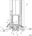
- the lower frame cross member 26 has a base profile 30, made of plastic, for example, two attachment profiles 31, 32 and a step profile 33 (cf. Fig.3 ).
- the attachment profiles 31, 32 and the tread profile 33 can each be made of aluminum, for example.
- the tread profile 33 is arranged flush with the inner covering 106, i.e., the surfaces of the tread profile 33 and the inner covering 106 are at the same height.
- a weather leg 36 extending along an extension direction E with an elastic seal 38 (also extending along the extension direction E) is arranged (cf. Fig.1-3 ).
- the extension direction E is oriented along or parallel to the longitudinal direction L when the sash 16 is in the closed position.
- the seal 38 projects downwards from the weatherstrip 36 along the direction of gravity g in such a way that, when the sash 16 is in the closed position, it rests sealingly on the sill surface 29 (cf. Fig.3 ).
- a through hole 43' is formed for fastening the lateral section 43 to the lateral wing overlap 18 by means of a screw (cf. Fig.1 and 4a ).
- the through hole 43' has a chamfered or countersunk section on the outside of the lateral section 43 (weather side) for sealing with the screw head, in particular a countersunk head.
- a receptacle 45 is formed which has a cross-section complementary to the seal 38 of the weather leg 36 and sealingly receives an end section of the seal 38 (cf. Fig.3 and 4b ).
- the receptacle 45 has a T-shaped cross-section.
- the end cap 40 has a (substantially cuboid-shaped) base section 44 in which the receptacle 45 is formed and from which the lateral section 43 extends in the example (cf. Fig.4b ) .
- a groove 48 is formed for sealingly receiving a front end section of the weather leg 36.
- the fastening section 47 extends, in particular, transversely to the above-mentioned direction of extension E away from the base section 46 of the end cap (cf. Fig.4b ).
- a coupling section 49 extends from the base section 44 along or parallel to the direction of extension E, which coupling section 49 penetrates into a corresponding pocket 61 on the weather leg 36, the pocket 61 being the web 62 of the weather leg 36 engaging under the wing 16 on its underside 24 (cf. Fig.3 ).
- a screw receptacle 64 is formed on the weatherboard 36 for receiving a screw shaft (screw-in section) of the screw 60.
- the base section 44 has on its upper side (oriented upwards along the direction of gravity g) a contact surface 50, by means of which the base section 44 contacts the wing 16 on its underside 24 (cf. Fig.4b ) .
- the threshold 28 has a gradient towards the outer side 14, wherein the threshold contact surface 42 of the downwardly projecting portion 41 of the end cap 40 is adapted to the gradient of the threshold 28 (cf. Fig.1 , 3 and 4b ).
- the threshold contact surface 42 is thus adapted to the slope of the threshold 28 such that, when the leaf 16 is in the closed position, the threshold contact surface 42 rests evenly and sealingly on the threshold surface 29.
- the threshold contact surface 42 of the downwardly projecting portion 41 and the threshold surface 29 of the threshold 28 can be oriented parallel to one another when the leaf 16 is in the closed position.
- the seal 38 is spaced at one or both of its front ends from the overlap seal 20 of the respective lateral wing overlap 18, wherein a portion of the end cap 40, in particular the base portion 44 of the end cap 40, is arranged at this spacing.
- the seal 38 deliberately ends at one or both of its front ends at a distance from the respective overlap seal 20, thereby creating space for a portion of the end cap 40.
- the end cap 40 is formed in one piece and made of elastic soft plastic.
- the invention proposes replacing the existing tripping edge (step) on a preferably outward-opening sash with a barrier-free threshold.
- a threshold is provided with a slope toward the outside, creating a slight offset (e.g., 5 mm) from the outer covering to the threshold surface or the floor inside, thereby reducing the barrier effect.
- the weather strip with its elastic seal is designed in such a way that the elastic seal can run onto the slope of the threshold when the leaf is closed or when the door is closed and interacts with the threshold at the bottom to form a seal horizontally across the width of the leaf.
Landscapes
- Engineering & Computer Science (AREA)
- Civil Engineering (AREA)
- Structural Engineering (AREA)
- Specific Sealing Or Ventilating Devices For Doors And Windows (AREA)
Priority Applications (1)
| Application Number | Priority Date | Filing Date | Title |
|---|---|---|---|
| EP23202137.8A EP4534793B1 (fr) | 2023-10-06 | 2023-10-06 | Ensemble porte ou fenêtre |
Applications Claiming Priority (1)
| Application Number | Priority Date | Filing Date | Title |
|---|---|---|---|
| EP23202137.8A EP4534793B1 (fr) | 2023-10-06 | 2023-10-06 | Ensemble porte ou fenêtre |
Publications (2)
| Publication Number | Publication Date |
|---|---|
| EP4534793A1 true EP4534793A1 (fr) | 2025-04-09 |
| EP4534793B1 EP4534793B1 (fr) | 2026-01-28 |
Family
ID=88295760
Family Applications (1)
| Application Number | Title | Priority Date | Filing Date |
|---|---|---|---|
| EP23202137.8A Active EP4534793B1 (fr) | 2023-10-06 | 2023-10-06 | Ensemble porte ou fenêtre |
Country Status (1)
| Country | Link |
|---|---|
| EP (1) | EP4534793B1 (fr) |
Citations (2)
| Publication number | Priority date | Publication date | Assignee | Title |
|---|---|---|---|---|
| DE102013110832A1 (de) * | 2013-09-30 | 2015-04-02 | Gealan Fenster-Systeme Gmbh | Vorrichtung zur Abdichtung von Tür- oder Fensterelementen |
| DE202017106040U1 (de) * | 2017-10-05 | 2017-11-16 | Gretsch-Unitas GmbH Baubeschläge | Türsystem |
-
2023
- 2023-10-06 EP EP23202137.8A patent/EP4534793B1/fr active Active
Patent Citations (2)
| Publication number | Priority date | Publication date | Assignee | Title |
|---|---|---|---|---|
| DE102013110832A1 (de) * | 2013-09-30 | 2015-04-02 | Gealan Fenster-Systeme Gmbh | Vorrichtung zur Abdichtung von Tür- oder Fensterelementen |
| DE202017106040U1 (de) * | 2017-10-05 | 2017-11-16 | Gretsch-Unitas GmbH Baubeschläge | Türsystem |
Also Published As
| Publication number | Publication date |
|---|---|
| EP4534793B1 (fr) | 2026-01-28 |
Similar Documents
| Publication | Publication Date | Title |
|---|---|---|
| EP2202378B1 (fr) | Seuil pouvant être installé en rattrapage pour fenêtre coulissante à soulèvement et son procédé de montage | |
| DE202008013043U1 (de) | Hebe-Schiebe-Fenster oder -Tür sowie Abdichtelement | |
| EP3259428B1 (fr) | Dispositif d'étanchéité pour éléments de fenêtre et éléments de porte | |
| EP3043017B1 (fr) | Systeme de drainage pour des elements de porte et de fenetre | |
| AT408566B (de) | Fenster, insbesondere dachfenster | |
| EP3581752B1 (fr) | Fenêtre | |
| EP0418629A1 (fr) | Panneaux pour une porte sectionnelle | |
| EP4534793A1 (fr) | Ensemble porte ou fenêtre | |
| DE20321194U1 (de) | Durchgangstür für Lamellentore mit austauschbaren Teilstücken | |
| DE4339467C1 (de) | Dachverglasungssystem | |
| EP1790816B1 (fr) | Porte en verre avec un joint descendant | |
| EP1279791B1 (fr) | Joint d'étanchéité descendant pour porte | |
| EP3715576B1 (fr) | Pièce d'assemblage de seuil universelle pourvue d'élément interchangeable | |
| CH688102A5 (de) | Falt- oder Schwingfluegeltor. | |
| DE102018112434A1 (de) | Fenster | |
| DE202007002319U1 (de) | Schließteil | |
| DE202017106040U1 (de) | Türsystem | |
| EP3141687A1 (fr) | Joint d'etancheite antiretour d'une porte | |
| EP4026979B1 (fr) | Installation de porte hermétique | |
| EP2554082B1 (fr) | Séparation de douche | |
| EP2362047B1 (fr) | Porte à levage coulissante ou fenêtre à levage coulissant | |
| DE10011576A1 (de) | Fenster- oder Türrahmen für Container o. dgl. | |
| EP1582674A2 (fr) | Charnière en feuillure avec bande d'étanchéité | |
| DE202009003391U1 (de) | Profilsystem für eine Haustür und daraus hergestellte Haustüranlage | |
| EP4245957A1 (fr) | Cadre de porte avec seuil |
Legal Events
| Date | Code | Title | Description |
|---|---|---|---|
| PUAI | Public reference made under article 153(3) epc to a published international application that has entered the european phase |
Free format text: ORIGINAL CODE: 0009012 |
|
| STAA | Information on the status of an ep patent application or granted ep patent |
Free format text: STATUS: REQUEST FOR EXAMINATION WAS MADE |
|
| 17P | Request for examination filed |
Effective date: 20240508 |
|
| AK | Designated contracting states |
Kind code of ref document: A1 Designated state(s): AL AT BE BG CH CY CZ DE DK EE ES FI FR GB GR HR HU IE IS IT LI LT LU LV MC ME MK MT NL NO PL PT RO RS SE SI SK SM TR |
|
| GRAP | Despatch of communication of intention to grant a patent |
Free format text: ORIGINAL CODE: EPIDOSNIGR1 |
|
| STAA | Information on the status of an ep patent application or granted ep patent |
Free format text: STATUS: GRANT OF PATENT IS INTENDED |
|
| INTG | Intention to grant announced |
Effective date: 20250919 |
|
| GRAS | Grant fee paid |
Free format text: ORIGINAL CODE: EPIDOSNIGR3 |
|
| GRAA | (expected) grant |
Free format text: ORIGINAL CODE: 0009210 |
|
| STAA | Information on the status of an ep patent application or granted ep patent |
Free format text: STATUS: THE PATENT HAS BEEN GRANTED |
|
| P01 | Opt-out of the competence of the unified patent court (upc) registered |
Free format text: CASE NUMBER: UPC_APP_0016974_4534793/2025 Effective date: 20251211 |
|
| AK | Designated contracting states |
Kind code of ref document: B1 Designated state(s): AL AT BE BG CH CY CZ DE DK EE ES FI FR GB GR HR HU IE IS IT LI LT LU LV MC ME MK MT NL NO PL PT RO RS SE SI SK SM TR |
|
| REG | Reference to a national code |
Ref country code: CH Ref legal event code: F10 Free format text: ST27 STATUS EVENT CODE: U-0-0-F10-F00 (AS PROVIDED BY THE NATIONAL OFFICE) Effective date: 20260128 Ref country code: GB Ref legal event code: FG4D Free format text: NOT ENGLISH Ref country code: CH Ref legal event code: R17 Free format text: ST27 STATUS EVENT CODE: U-0-0-R10-R17 (AS PROVIDED BY THE NATIONAL OFFICE) Effective date: 20260128 |
|
| REG | Reference to a national code |
Ref country code: DE Ref legal event code: R096 Ref document number: 502023002864 Country of ref document: DE |
|
| REG | Reference to a national code |
Ref country code: IE Ref legal event code: FG4D Free format text: LANGUAGE OF EP DOCUMENT: GERMAN |