EP4534862A2 - Dispositifs et procédés de verrouillage de tige filetée - Google Patents
Dispositifs et procédés de verrouillage de tige filetée Download PDFInfo
- Publication number
- EP4534862A2 EP4534862A2 EP24205117.5A EP24205117A EP4534862A2 EP 4534862 A2 EP4534862 A2 EP 4534862A2 EP 24205117 A EP24205117 A EP 24205117A EP 4534862 A2 EP4534862 A2 EP 4534862A2
- Authority
- EP
- European Patent Office
- Prior art keywords
- plunger
- threaded
- threaded rod
- passage
- section
- Prior art date
- Legal status (The legal status is an assumption and is not a legal conclusion. Google has not performed a legal analysis and makes no representation as to the accuracy of the status listed.)
- Pending
Links
Images








Classifications
-
- F—MECHANICAL ENGINEERING; LIGHTING; HEATING; WEAPONS; BLASTING
- F16—ENGINEERING ELEMENTS AND UNITS; GENERAL MEASURES FOR PRODUCING AND MAINTAINING EFFECTIVE FUNCTIONING OF MACHINES OR INSTALLATIONS; THERMAL INSULATION IN GENERAL
- F16B—DEVICES FOR FASTENING OR SECURING CONSTRUCTIONAL ELEMENTS OR MACHINE PARTS TOGETHER, e.g. NAILS, BOLTS, CIRCLIPS, CLAMPS, CLIPS OR WEDGES; JOINTS OR JOINTING
- F16B37/00—Nuts or like thread-engaging members
- F16B37/08—Quickly-detachable or mountable nuts, e.g. consisting of two or more parts; Nuts movable along the bolt after tilting the nut
- F16B37/0807—Nuts engaged from the end of the bolt, e.g. axially slidable nuts
- F16B37/0857—Nuts engaged from the end of the bolt, e.g. axially slidable nuts with the threaded portions of the nut engaging the thread of the bolt by the action of one or more springs or resilient retaining members
-
- F—MECHANICAL ENGINEERING; LIGHTING; HEATING; WEAPONS; BLASTING
- F16—ENGINEERING ELEMENTS AND UNITS; GENERAL MEASURES FOR PRODUCING AND MAINTAINING EFFECTIVE FUNCTIONING OF MACHINES OR INSTALLATIONS; THERMAL INSULATION IN GENERAL
- F16L—PIPES; JOINTS OR FITTINGS FOR PIPES; SUPPORTS FOR PIPES, CABLES OR PROTECTIVE TUBING; MEANS FOR THERMAL INSULATION IN GENERAL
- F16L25/00—Construction or details of pipe joints not provided for in, or of interest apart from, groups F16L13/00 - F16L23/00
- F16L25/14—Joints for pipes of different diameters or cross-section
-
- E—FIXED CONSTRUCTIONS
- E04—BUILDING
- E04B—GENERAL BUILDING CONSTRUCTIONS; WALLS, e.g. PARTITIONS; ROOFS; FLOORS; CEILINGS; INSULATION OR OTHER PROTECTION OF BUILDINGS
- E04B1/00—Constructions in general; Structures which are not restricted either to walls, e.g. partitions, or floors or ceilings or roofs
- E04B1/38—Connections for building structures in general
- E04B1/41—Connecting devices specially adapted for embedding in concrete or masonry
- E04B1/4114—Elements with sockets
- E04B1/4121—Elements with sockets with internal threads or non-adjustable captive nuts
-
- F—MECHANICAL ENGINEERING; LIGHTING; HEATING; WEAPONS; BLASTING
- F16—ENGINEERING ELEMENTS AND UNITS; GENERAL MEASURES FOR PRODUCING AND MAINTAINING EFFECTIVE FUNCTIONING OF MACHINES OR INSTALLATIONS; THERMAL INSULATION IN GENERAL
- F16B—DEVICES FOR FASTENING OR SECURING CONSTRUCTIONAL ELEMENTS OR MACHINE PARTS TOGETHER, e.g. NAILS, BOLTS, CIRCLIPS, CLAMPS, CLIPS OR WEDGES; JOINTS OR JOINTING
- F16B9/00—Connections of rods or tubular parts to flat surfaces at an angle
- F16B9/05—Connections of rods or tubular parts to flat surfaces at an angle by way of an intermediate member
- F16B9/054—Connections of rods or tubular parts to flat surfaces at an angle by way of an intermediate member the intermediate member being threaded
Definitions
- Some aspects of the disclosure can provide the device of any previous aspect in which the first and second plunger halves are seated against each other in the closed configuration.
- Some aspects of the disclosure can provide the device of any previous aspect in which the first threaded section and the second threaded section include threadless areas, within the passage, adjacent the split lines.
- Some aspects of the disclosure can provide the device of any previous aspect in which, with the plunger in the closed configuration, a shape of the passage as viewed in an axial direction is ovular, with internal major diameters of the ovular shape extending between the split lines at the first threaded sections and the second threaded sections.
- Some aspects of the disclosure can provide the device of any previous aspect in which the outer surface defines an ovular outer periphery in the closed configuration and a circular outer periphery in the open configuration.
- Some aspects of the disclosure can provide a method of securing threaded rods.
- the method can include providing a threaded rod locking device having a housing with an internal bore, and a plunger within the internal bore including a first plunger body with a first threaded section and a second plunger body with a second threaded section, aligning a threaded rod with a passage defined by the first and second plunger bodies, with the plunger in a closed configuration, in which the first and second threaded sections define an ovular cross-section of the passage, axially inserting the threaded rod into the internal bore to urge the plunger, against a biasing force, into an open configuration, in which the first and second threaded sections define a circular cross-section of the passage to receive the threaded rod, and axially loading the threaded rod to urge the first and second plunger bodies to the closed configuration to secure the threaded rod within the housing.
- Some aspects of the disclosure can provide the device of any previous aspect in which the threaded rod is axially inserted into the internal bore by axial engagement of the threaded rod with one or more tapered sections of the passage that are defined at one or more of: an entrance to the passage, or a transition within the passage between different thread diameters.
- the threaded rod locking device can include parts that move within a housing of an anchor that are urged open upon contact with an inserted threaded rod and self-close to engage the threads of the threaded rod for securement of the threaded rod within the anchor.
- a threaded rod locking device can have a set of plungers configured to separate to receive a threaded rod therebetween and engage the threads of the inserted threaded rod.
- the set of plungers can be biased toward a closed configuration to secure the threaded rod within the anchor.
- FIGS. 1-3 show a coupler 100 for coupling a pair of threaded rods (e.g., a set of threaded rods like threaded rod 50 shown in FIG. 6 ).
- the coupler 100 has a housing 102, a back plate 104 (here shown as a threaded nipple), and a threaded rod locking device 106.
- the housing 102 includes a first end 108, a second end 110, and an internal bore 112 extending between first and second bore ends (e.g., extending from the first end 108 to the second end 110 in the example shown).
- the internal bore 112 has a first diameter 114 adjacent the first end 108, which remains constant as the internal bore 112 extends toward the second end 110. Adj acent the second end 110, the internal bore 112 has a tapered section 116, which tapers inward from the first diameter 114 to a second diameter 118 to an opening 120.
- the threaded rod locking device 106 is shown with a plunger 122 and a spring 130 or other known biasing member (e.g., elastomer bodies, integral prong structures, etc.).
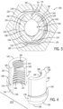
- the plunger 122 is split along a split plane 124 to provide separate first and second plunger bodies, which may be separate plunger halves 126, 128, as shown (e.g., substantially identical halves, as shown, separated by corresponding split lines on opposing sides of the plunger 122).
- the plunger halves 126, 128 are received together within the internal bore 112 to collectively define a passage 164 to receive threaded rods (as further discussed below).
- the inner arcuate surface 144, 146 includes a first threaded section 156, 158 adjacent the first end 132, 134 and a second threaded section 160, 162 adjacent the second end 136, 138.
- first and second plunger halves 126, 128 With the first and second plunger halves 126, 128 in a closed position (e.g., as shown in FIG. 9 ) the first threaded sections 156, 158 can be sized to secure within the passage 164 a threaded rod of a different size than the second threaded sections 160, 162.
- first threaded sections 156, 158 can be sized to collectively receive a 1 ⁇ 4" threaded rod and the second threaded sections 160, 162 can be sized to collectively receive a 3/8" threaded rod.
- Other example combinations of the first threaded sections 156, 158 and the second threaded sections 160, 162 can include 3/8" and 1 ⁇ 2"; 1 ⁇ 2" and 5/8"; and 5/8" and 3 ⁇ 4". Other combinations are also contemplated.
- first chamfer 166, 168 can include a partial thread to allow for smoother engagement of a threaded rod (e.g., the threaded rod 50 shown in FIG. 7 ) with the threads of the first threaded sections 156, 158.
- a second chamfer 172, 174 or other taper can also be provided at the second end 136, 138, at an entrance to the passage 164, to aid in guiding a threaded rod into the plunger 122.
- the second chamfer 172, 174 can be disposed at an angle of about 20 degrees from the central axis 170.
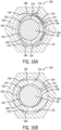
- the second chamfer 172, 174 can define a circular cross-section (and corresponding circular conical section overall) when the plunger 122 is in the closed configuration (see, e.g., FIG. 5B ).
- initial insertion of a threaded rod can easily move the plunger 122 from the closed configuration toward the open configuration without binding because the plunger 122 can translate uniformly along the full chamfered circumference to urge the plunger halves 126, 128 axially into the housing 102 and radially apart from each other.
- non-circular cross-section of the passage 164 at the entrance to the first threaded sections 156, 158 can also allow for significantly smoother insertion of a threaded rod, including because a tapered thread depth (as further detailed below) can help to prevent binding of the threads of the plunger 122 with the threads of the rod.
- the threads of the first threaded sections 156, 158 and the second threaded sections 160, 162 can be configured to change in depth along the inner arcuate surface 144, 146 (e.g., continuously along a circumference of the corresponding threads, in some cases).
- the threads can transition from a deepest depth at a point along the inner arcuate surface 144, 146 farthest from the split plane 124 to shallowest depth adjacent the split plane 124.
- the threaded sections 156, 158 can provide areas of zero thread depth (i.e., threadless areas) adjacent to the split plane 124 in some cases. As shown in FIG.
- the reduction in thread depth can be accomplished by reducing the peaks of the threads down to the valley of the threads and can provide an area with no threads at the split plane 124. Therefore, the inner diameter of the passage 164 is largest at the split plane 124.
- the female threads of a threaded section of the plunger may define a major thread diameter (i.e., a width of the passage measured at the roots of the threads, perpendicular to the split plane, and through the central axis) that is substantially equal to a major thread diameter of the male threads of the corresponding threaded rod (i.e., a diameter of the rod measured at the crests of the threads).
- the roots of the threads of the plunger may define a circular cross-section when the plunger is in a closed configuration to allow easy rotational adjustment of the threaded rod.
- the plunger threads generally define a minor thread diameter (i.e., a diameter of the between the crests of the threads, perpendicular to the split plane, and through the central axis) that is smaller than the major thread diameter of the threaded rod and thus extend into threaded engagement with the thread rod to secure the threaded rod against axial movement.
- the threads of the plunger may define a non-circular (e.g., ovular) cross-section when the plungers are in the closed configuration.
- an open configuration for a first threaded rod diameter may correspond to a different spacing between plunger bodies - and different major and minor thread diameters - than an open configuration for a second, different threaded rod diameter.
- FIG. 2 the combination of the threaded rod locking device 106, the housing 102, and the back plate 104 is shown.
- the threaded rod locking device 106 is positioned within the internal bore 112 of the housing 102 with the spring 130 biased between the back plate 104 and the ledge sections 148, 150 of the first and second plunger halves 126, 128.
- the spring 130 is therefore arranged external to and surrounding at least a portion of the plunger 122.
- the shape of the combined outer peripheries of the first and second plunger halves 126, 128 permits this described movement of the first and second plunger halves 126, 128 during the transition from the closed configuration to the open configuration without interfering with the spring 130.
- the spring 130 or other circular biasing element can also thus engage firmly with the outer (e.g., circular) periphery of the plunger 122 in the (maximum-diameter) open configuration, to prevent overseparation of the plunger halves 126, 128 or underside splaying of the plunger halves 126, 128 away from each other.
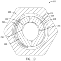
- FIG. 19 also provides a view of the non-circular shape of the outer periphery of a plunger 222 in a closed position.
- threaded rod 50 to be inserted into the passage 164 without the substantial interference that would be encountered if the threads in the first threaded sections 156, 158 maintained a continuous depth along the entire respective inner arcuate surfaces 144, 146.
- threaded rods can be easily inserted into engagement with the coupler 100 even at relatively large installation distances (e.g., to hang rod from relatively high ceilings), in contrast to various conventional designs.
- FIGS. 9-11A provide views of the threaded rod locking device 106 returned to the closed configuration to secure the threaded rod 50 within the coupler 100. Removing the insertion force previously applied to the threaded rod 50 permits the bias force of the spring 130 (e.g., acting between the back plate 104 and the ledge sections 148, 150) or a corresponding axial loading of the rod 50 to urge the first and second plunger halves 126, 128 back downward toward the second end 110 of the housing 102.
- the bias force of the spring 130 e.g., acting between the back plate 104 and the ledge sections 148, 150
- a corresponding axial loading of the rod 50 to urge the first and second plunger halves 126, 128 back downward toward the second end 110 of the housing 102.
- the tapered sections 152, 154 on the outer arcuate surface 140, 142 of the first and second plunger halves 126, 128 correspondingly translate along the tapered section 116 of the housing 102 to move the first and second plunger halves 126, 128 back toward the central axis 170 and back toward the closed configuration, so that the first threaded sections 156, 158 engage with the threads of the threaded rod 50.
- the corresponding threads may engage the threaded rod 50 over only part of the circumference of the threaded rod and of the threaded sections 160, 162.
- the threaded sections 156, 158 may contact the threaded rod 50 along a full circumferential extent of the thread of the sections 156, 158 and the corresponding circular arcs of the circular cross-section of the passage (but not over the gap between the spaced-apart plunger halves 126, 128 or at any threadless sections).
- FIGS. 12-16B depict the installation of a larger threaded rod 60 (e.g., a 1/2" threaded rod) into the coupler 100.
- FIG. 12 is provided as a reference drawing of the threaded rod 60 and the coupler 100 to illustrate the orientation of the respective cross-sectional views shown in FIGS. 13-16 , but is not necessarily accurate as to the actual position of the threaded rod 60 within the coupler 100 as shown in some of the cross-sectional views (which collectively illustrated axial translation of the rod 60 within the coupler 100).
- the threaded rod 60 can be inserted through the opening 120 of the housing 102 to contact the second chamfers 172, 174 of the first and second plunger halves 126, 128.
- the threaded rod 60 can be inserted through the opening 120 of the housing 102 to contact the second chamfers 172, 174 of the first and second plunger halves 126, 128.
- an insertion force large enough to overcome the bias force of the spring 130 urges the first and second plunger halves 126, 128 toward the back plate 104 and outward away from the central axis 170 170 (e.g., due to the angled engagement of the rod and plunger threads).
- the shape of the passage 164 converts from having a pointed oval or other ovular shape to a circular chape (e.g., to extend along arcs of a circle with an internal diameter substantially equal to an outer diameter of the threaded rod 60).
- a circular chape e.g., to extend along arcs of a circle with an internal diameter substantially equal to an outer diameter of the threaded rod 60.
- the threaded rod 60 can be inserted more easily into the passage 164.
- the threaded rod 60 can be inserted as far as contacting the first chamfers 166, 168.
- the tapered sections 152, 154 on the outer arcuate surface 140, 142 of the first and second plunger halves 126, 128 correspondingly translate along the tapered section 116 of the housing 102 to move the first and second plunger halves 126, 128 back toward the central axis 170 and back toward the closed configuration, in which the second threaded sections 160, 162 engage with the threads of the threaded rod 60.
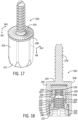
- FIGS. 17-19 illustrate an embodiment of an anchor bolt 200, according to the invention, as also can be equipped with a threaded rod locking device 206.
- the anchor bolt 200 can be configured to be installed within a structure (e.g., a concrete structure) after the concrete has hardened to a point in which a hole can be drilled and an anchor installed.
- the anchor bolt 200 is similar to the coupler 100 described above.
- similar numbering in the 200 series is used for the anchor bolt 200 and discussion of similarly numbered or names components relative to the coupler 100 also apply to the anchor bolt 200, and vice versa, unless otherwise noted or required.
- the anchor bolt 200 includes a housing 202, a back plate 204, and the threaded rod locking device 206.
- the housing 202 has a first end 208, a second end 210 with an opening 220, and an internal bore 212.
- the threaded rod locking device 206 has the plunger 222 and a spring 230.
- the plunger 222 includes a first plunger half 226 and a second plunger half 228, each with a ledge section 248, 250; a tapered section 252, 254; a first threaded section 256, 258; and a second threaded section 260, 262 and is configured to receive and secure a threaded rod (e.g., the threaded rod 50 shown in FIG. 6 ) by pushing the threaded rod into the threaded rod locking device 206.
- a threaded rod e.g., the threaded rod 50 shown in FIG. 6
- FIGS. 20-22 illustrate an embodiment of a pre-set concrete anchor 300, according to the invention, as also can be equipped with a threaded rod locking device 306.
- the pre-set concrete anchor 300 can be configured to be installed within a structure (e.g., a metal deck) prior to concrete being poured thereon.
- the pre-set concrete anchor 300 is similar to the coupler 100 described above.
- similar numbering in the 300 series is used for the pre-set concrete anchor 300 and discussion of similarly numbered or names components relative to the coupler 100 also apply to the anchor 300, and vice versa, unless otherwise noted or required.
- the pre-set concrete anchor 300 includes a housing 302, a back plate 304, and the threaded rod locking device 306.
- the pre-set concrete anchor 300 can be installed through a plateau section of a metal deck.
- the tube 380 can be inserted through a hole (e.g., a 1.25" diameter hole) in the metal deck, with the holding fingers 384 being configured to bend inwards to pass through the hole and rebound outward to contact an underside of the metal deck.
- the holding plate 378 is then positioned against the topside of the metal deck, opposite the holding fingers 384. The metal deck is therefore captured between the holding fingers 384 and the holding plate 378. This arrangement is maintained by the holding spring 382 applying a biasing force between the flange 309 and the holding plate 378.
- the holding plate 378 can include a set of holes 386 through which fasteners can be received to secure the holding plate 378 to the metal deck.
- the tube 380 can be formed from plastic and the barrier 392 can be integrally formed with the tube 380.
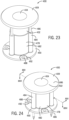
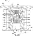
- FIGS. 23-29 illustrate an embodiment of a pre-set anchor 400, according to the invention, as also can be equipped with a threaded rod locking device 406.
- the pre-set anchor 400 can be configured to be installed within a structure (e.g., a plywood deck for the version of the pre-set anchor shown in FIGS. 23-26 or a metal pan deck for the version of the pre-set anchor shown in FIGS. 27-29 ) prior to concrete being poured thereon.
- the pre-set anchor 400 is similar to the coupler 100 described above.
- similar numbering in the 400 series is used for the pre-set anchor 400 and discussion of similarly numbered or names components relative to the coupler 100 also apply to the anchor 400, and vice versa, unless otherwise noted or required.
- the pre-cut lines 492 around each of the holes 488 predefine a location along which the holes can be separated from the base, so as the metal pan deck is removed the fasteners to break the base 478 at the pre-cut lines 492 to allow the fasteners, and the metal pan deck, to fall away.
- a list preceded by "one or more” (and variations thereon) and including “or” to separate listed elements indicates options of one or more of any or all of the listed elements.
- the phrases “one or more of A, B, or C" and “at least one of A, B, or C” indicate options of: one or more A; one or more B; one or more C; one or more A and one or more B; one or more B and one or more C; one or more A and one or more C; and one or more A, one or more B, and one or more C.
- a list preceded by "a plurality of" (and variations thereon) and including “or” to separate listed elements indicates options of one or more of each of multiple of the listed elements.
Landscapes
- Engineering & Computer Science (AREA)
- General Engineering & Computer Science (AREA)
- Mechanical Engineering (AREA)
- Architecture (AREA)
- Physics & Mathematics (AREA)
- Electromagnetism (AREA)
- Civil Engineering (AREA)
- Structural Engineering (AREA)
- Mutual Connection Of Rods And Tubes (AREA)
- Fluid-Damping Devices (AREA)
Applications Claiming Priority (1)
| Application Number | Priority Date | Filing Date | Title |
|---|---|---|---|
| US202363588363P | 2023-10-06 | 2023-10-06 |
Publications (2)
| Publication Number | Publication Date |
|---|---|
| EP4534862A2 true EP4534862A2 (fr) | 2025-04-09 |
| EP4534862A3 EP4534862A3 (fr) | 2025-06-11 |
Family
ID=93037454
Family Applications (1)
| Application Number | Title | Priority Date | Filing Date |
|---|---|---|---|
| EP24205117.5A Pending EP4534862A3 (fr) | 2023-10-06 | 2024-10-07 | Dispositifs et procédés de verrouillage de tige filetée |
Country Status (2)
| Country | Link |
|---|---|
| US (1) | US20250116360A1 (fr) |
| EP (1) | EP4534862A3 (fr) |
Cited By (1)
| Publication number | Priority date | Publication date | Assignee | Title |
|---|---|---|---|---|
| GB2700981A (en) * | 2024-06-06 | 2026-04-01 | Gripple Ltd | Improvements in or relating to connectors |
Families Citing this family (2)
| Publication number | Priority date | Publication date | Assignee | Title |
|---|---|---|---|---|
| US20200325924A1 (en) * | 2019-04-12 | 2020-10-15 | Black & Decker Inc. | Cast-in place anchor with multi-use jaws and removable nose-piece |
| USD1089566S1 (en) * | 2022-03-31 | 2025-08-19 | Nidec Corporation | Plug of pipe joint |
Family Cites Families (30)
| Publication number | Priority date | Publication date | Assignee | Title |
|---|---|---|---|---|
| US991517A (en) * | 1910-06-24 | 1911-05-09 | Clements Co | Anchor. |
| US1475907A (en) * | 1922-04-08 | 1923-11-27 | Volman Ani | Securing element |
| US2294745A (en) * | 1940-12-03 | 1942-09-01 | Goetz John | Jack |
| US4974888A (en) * | 1988-07-25 | 1990-12-04 | The Vendo Company | Fastening apparatus |
| US5378100A (en) * | 1993-04-16 | 1995-01-03 | Fullerton; Robert L. | Method and apparatus for rapidly engaging and disengaging threaded coupling members |
| JP3319566B2 (ja) * | 1995-03-31 | 2002-09-03 | 株式会社イナックス | 連結用クリップ |
| US6053655A (en) * | 1998-07-30 | 2000-04-25 | The United States Of America As Represented By The Secretary Of The Army | Fastener with cam engagement |
| JP4486240B2 (ja) * | 2000-09-25 | 2010-06-23 | 薫 種市 | ナット |
| US6361260B1 (en) * | 2000-11-03 | 2002-03-26 | Wendell E. Schirrmacher | Quick locking fastener |
| US8534974B2 (en) * | 2006-07-29 | 2013-09-17 | Ronald A. Smith | Thread clamping device with improved locking distance |
| US7985041B2 (en) * | 2008-10-08 | 2011-07-26 | Simpson Strong-Tie Company, Inc. | Symmetrically stepped bore coupler nut |
| US8998155B2 (en) * | 2008-10-30 | 2015-04-07 | Erico International Corporation | Quick threaded rod locking devices and method |
| US8061945B2 (en) * | 2008-11-24 | 2011-11-22 | Zipnut Technology, Llc | Quick-acting threaded fastener |
| US20100133810A1 (en) * | 2008-11-29 | 2010-06-03 | Krohn Kenneth P | Device for connecting to ducts of various sizes and shapes |
| US20100283237A1 (en) * | 2009-01-24 | 2010-11-11 | Krohn Kenneth P | Device for connecting to ducts of various sizes and shapes |
| US8646339B2 (en) * | 2011-02-07 | 2014-02-11 | Ronald A. Smith | Thread clamping device including internal sensing and reporting |
| CA2867842C (fr) * | 2011-03-18 | 2018-01-16 | Thomas M. Espinosa | Ensemble d'accouplement pour ancrage a beton et support de tige d'ancrage |
| US9695861B2 (en) * | 2011-08-03 | 2017-07-04 | Qwikline Industrial Products, Inc. | Split nut compression fastener system |
| CA2918189C (fr) * | 2012-08-06 | 2018-03-27 | Thomas M. Espinosa | Ensembles support et ancre a beton |
| CN105579717A (zh) * | 2013-05-03 | 2016-05-11 | 爱瑞柯国际公司 | 快速螺杆锁紧装置及方法 |
| US9394706B2 (en) * | 2013-10-08 | 2016-07-19 | Simpson Strong-Tie Company, Inc. | Concrete anchor |
| US9163655B2 (en) * | 2014-01-14 | 2015-10-20 | Kaoru Taneichi | Thrust nut |
| US9181691B2 (en) * | 2014-03-25 | 2015-11-10 | William J. Thompson | Quick connect anchor for poured concrete ceilings on metal or wood decks |
| EP3126686A4 (fr) * | 2014-04-01 | 2017-11-29 | Erico International Corporation | Dispositif et procédé de verrouillage d'objet cylindrique |
| CN107429866B (zh) * | 2015-03-04 | 2019-05-21 | 法斯泰斯特公司 | 宽公差流体连接器 |
| CA3014187C (fr) * | 2016-02-11 | 2021-03-16 | Cetres Holdings, Llc | Bouchons et corps d'ancrage de beton |
| EP3388699B1 (fr) * | 2017-04-13 | 2021-09-01 | Black & Decker Inc. | Ensemble d'ancrage de béton à écrou à déclic |
| US10927874B2 (en) * | 2018-03-16 | 2021-02-23 | Black & Decker Inc. | Snap nut concrete anchor assembly |
| US20200325924A1 (en) * | 2019-04-12 | 2020-10-15 | Black & Decker Inc. | Cast-in place anchor with multi-use jaws and removable nose-piece |
| US11608630B2 (en) * | 2019-04-12 | 2023-03-21 | Black & Decker Inc. | Cast-in place anchor with lockable jaw assembly |
-
2024
- 2024-10-07 EP EP24205117.5A patent/EP4534862A3/fr active Pending
- 2024-10-07 US US18/908,400 patent/US20250116360A1/en active Pending
Cited By (1)
| Publication number | Priority date | Publication date | Assignee | Title |
|---|---|---|---|---|
| GB2700981A (en) * | 2024-06-06 | 2026-04-01 | Gripple Ltd | Improvements in or relating to connectors |
Also Published As
| Publication number | Publication date |
|---|---|
| US20250116360A1 (en) | 2025-04-10 |
| EP4534862A3 (fr) | 2025-06-11 |
Similar Documents
| Publication | Publication Date | Title |
|---|---|---|
| US20250116360A1 (en) | Threaded rod locking devices and methods | |
| US11447943B2 (en) | Pipe connector | |
| CN113756414B (zh) | 线性排水组件 | |
| US6634034B2 (en) | Adjustable toilet flange assembly | |
| TWI805805B (zh) | 包含用於金屬蓋板的鑄入式錨的系統與方法 | |
| US10030369B2 (en) | Faucet assembly fixture | |
| US11384866B2 (en) | Pipe clamp | |
| EP3067574A1 (fr) | Un clip et une structure de fixation | |
| CA2934777A1 (fr) | Dispositif d'accouplement | |
| KR20180126973A (ko) | 건축 슬래브용 인서트 | |
| CN109425089B (zh) | 风口安装结构、室内机及空调机组 | |
| CN210739092U (zh) | 一种可快速装卸的螺帽组件 | |
| EP2992229B1 (fr) | Dispositif de blocage rapide de tige filetée | |
| KR102128485B1 (ko) | 건축용 슬리브의 자전방지 기능이 부여된 미세 신장조절 조절테 결합구조 | |
| US20080038079A1 (en) | Adjustable concrete drop-in anchor | |
| KR20110103071A (ko) | 높이조절이 가능한 스프링클러의 고정장치 | |
| KR200481431Y1 (ko) | 고정구 | |
| GB2586467A (en) | Wall fixing | |
| JP2609972B2 (ja) | 継手支持固定具 | |
| EP4546584A2 (fr) | Support de montage pour composants électriques | |
| JPH0210728Y2 (fr) | ||
| US11680598B2 (en) | Fixing device | |
| JPH094766A (ja) | 継手支持固定具 | |
| JPS587853Y2 (ja) | コンクリ−ト構築物に埋込む照明器具等の取付け具 | |
| JPH0926057A (ja) | 水栓金具の取付具 |
Legal Events
| Date | Code | Title | Description |
|---|---|---|---|
| PUAI | Public reference made under article 153(3) epc to a published international application that has entered the european phase |
Free format text: ORIGINAL CODE: 0009012 |
|
| STAA | Information on the status of an ep patent application or granted ep patent |
Free format text: STATUS: THE APPLICATION HAS BEEN PUBLISHED |
|
| AK | Designated contracting states |
Kind code of ref document: A2 Designated state(s): AL AT BE BG CH CY CZ DE DK EE ES FI FR GB GR HR HU IE IS IT LI LT LU LV MC ME MK MT NL NO PL PT RO RS SE SI SK SM TR |
|
| PUAL | Search report despatched |
Free format text: ORIGINAL CODE: 0009013 |
|
| AK | Designated contracting states |
Kind code of ref document: A3 Designated state(s): AL AT BE BG CH CY CZ DE DK EE ES FI FR GB GR HR HU IE IS IT LI LT LU LV MC ME MK MT NL NO PL PT RO RS SE SI SK SM TR |
|
| RIC1 | Information provided on ipc code assigned before grant |
Ipc: F16B 37/08 20060101AFI20250507BHEP |
|
| STAA | Information on the status of an ep patent application or granted ep patent |
Free format text: STATUS: REQUEST FOR EXAMINATION WAS MADE |
|
| 17P | Request for examination filed |
Effective date: 20251211 |
|
| GRAP | Despatch of communication of intention to grant a patent |
Free format text: ORIGINAL CODE: EPIDOSNIGR1 |
|
| STAA | Information on the status of an ep patent application or granted ep patent |
Free format text: STATUS: GRANT OF PATENT IS INTENDED |
|
| INTG | Intention to grant announced |
Effective date: 20260529 |