EP4534865A1 - Palier suiveur, module de palier suiveur, et procédé de fabrication d'élément interne pour palier suiveur - Google Patents
Palier suiveur, module de palier suiveur, et procédé de fabrication d'élément interne pour palier suiveur Download PDFInfo
- Publication number
- EP4534865A1 EP4534865A1 EP23823632.7A EP23823632A EP4534865A1 EP 4534865 A1 EP4534865 A1 EP 4534865A1 EP 23823632 A EP23823632 A EP 23823632A EP 4534865 A1 EP4534865 A1 EP 4534865A1
- Authority
- EP
- European Patent Office
- Prior art keywords
- mass
- less
- circumferential surface
- diameter
- follower bearing
- Prior art date
- Legal status (The legal status is an assumption and is not a legal conclusion. Google has not performed a legal analysis and makes no representation as to the accuracy of the status listed.)
- Pending
Links
Images









Classifications
-
- F—MECHANICAL ENGINEERING; LIGHTING; HEATING; WEAPONS; BLASTING
- F16—ENGINEERING ELEMENTS AND UNITS; GENERAL MEASURES FOR PRODUCING AND MAINTAINING EFFECTIVE FUNCTIONING OF MACHINES OR INSTALLATIONS; THERMAL INSULATION IN GENERAL
- F16C—SHAFTS; FLEXIBLE SHAFTS; ELEMENTS OR CRANKSHAFT MECHANISMS; ROTARY BODIES OTHER THAN GEARING ELEMENTS; BEARINGS
- F16C13/00—Rolls, drums, discs, or the like; Bearings or mountings therefor
- F16C13/006—Guiding rollers, wheels or the like, formed by or on the outer element of a single bearing or bearing unit, e.g. two adjacent bearings, whose ratio of length to diameter is generally less than one
-
- F—MECHANICAL ENGINEERING; LIGHTING; HEATING; WEAPONS; BLASTING
- F16—ENGINEERING ELEMENTS AND UNITS; GENERAL MEASURES FOR PRODUCING AND MAINTAINING EFFECTIVE FUNCTIONING OF MACHINES OR INSTALLATIONS; THERMAL INSULATION IN GENERAL
- F16C—SHAFTS; FLEXIBLE SHAFTS; ELEMENTS OR CRANKSHAFT MECHANISMS; ROTARY BODIES OTHER THAN GEARING ELEMENTS; BEARINGS
- F16C19/00—Bearings with rolling contact, for exclusively rotary movement
- F16C19/22—Bearings with rolling contact, for exclusively rotary movement with bearing rollers essentially of the same size in one or more circular rows, e.g. needle bearings
- F16C19/24—Bearings with rolling contact, for exclusively rotary movement with bearing rollers essentially of the same size in one or more circular rows, e.g. needle bearings for radial load mainly
- F16C19/26—Bearings with rolling contact, for exclusively rotary movement with bearing rollers essentially of the same size in one or more circular rows, e.g. needle bearings for radial load mainly with a single row of rollers
-
- F—MECHANICAL ENGINEERING; LIGHTING; HEATING; WEAPONS; BLASTING
- F16—ENGINEERING ELEMENTS AND UNITS; GENERAL MEASURES FOR PRODUCING AND MAINTAINING EFFECTIVE FUNCTIONING OF MACHINES OR INSTALLATIONS; THERMAL INSULATION IN GENERAL
- F16C—SHAFTS; FLEXIBLE SHAFTS; ELEMENTS OR CRANKSHAFT MECHANISMS; ROTARY BODIES OTHER THAN GEARING ELEMENTS; BEARINGS
- F16C19/00—Bearings with rolling contact, for exclusively rotary movement
- F16C19/22—Bearings with rolling contact, for exclusively rotary movement with bearing rollers essentially of the same size in one or more circular rows, e.g. needle bearings
- F16C19/44—Needle bearings
- F16C19/46—Needle bearings with one row or needles
- F16C19/466—Needle bearings with one row or needles comprising needle rollers and an outer ring, i.e. subunit without inner ring
-
- F—MECHANICAL ENGINEERING; LIGHTING; HEATING; WEAPONS; BLASTING
- F16—ENGINEERING ELEMENTS AND UNITS; GENERAL MEASURES FOR PRODUCING AND MAINTAINING EFFECTIVE FUNCTIONING OF MACHINES OR INSTALLATIONS; THERMAL INSULATION IN GENERAL
- F16C—SHAFTS; FLEXIBLE SHAFTS; ELEMENTS OR CRANKSHAFT MECHANISMS; ROTARY BODIES OTHER THAN GEARING ELEMENTS; BEARINGS
- F16C35/00—Rigid support of bearing units; Housings, e.g. caps, covers
- F16C35/04—Rigid support of bearing units; Housings, e.g. caps, covers in the case of ball or roller bearings
- F16C35/06—Mounting or dismounting of ball or roller bearings; Fixing them onto shaft or in housing
- F16C35/063—Fixing them on the shaft
-
- F—MECHANICAL ENGINEERING; LIGHTING; HEATING; WEAPONS; BLASTING
- F16—ENGINEERING ELEMENTS AND UNITS; GENERAL MEASURES FOR PRODUCING AND MAINTAINING EFFECTIVE FUNCTIONING OF MACHINES OR INSTALLATIONS; THERMAL INSULATION IN GENERAL
- F16H—GEARING
- F16H53/00—Cams or cam-followers, e.g. rollers for gearing mechanisms
- F16H53/06—Cam-followers
-
- F—MECHANICAL ENGINEERING; LIGHTING; HEATING; WEAPONS; BLASTING
- F16—ENGINEERING ELEMENTS AND UNITS; GENERAL MEASURES FOR PRODUCING AND MAINTAINING EFFECTIVE FUNCTIONING OF MACHINES OR INSTALLATIONS; THERMAL INSULATION IN GENERAL
- F16C—SHAFTS; FLEXIBLE SHAFTS; ELEMENTS OR CRANKSHAFT MECHANISMS; ROTARY BODIES OTHER THAN GEARING ELEMENTS; BEARINGS
- F16C2204/00—Metallic materials; Alloys
- F16C2204/60—Ferrous alloys, e.g. steel alloys
- F16C2204/62—Low carbon steel, i.e. carbon content below 0.4 wt%
-
- F—MECHANICAL ENGINEERING; LIGHTING; HEATING; WEAPONS; BLASTING
- F16—ENGINEERING ELEMENTS AND UNITS; GENERAL MEASURES FOR PRODUCING AND MAINTAINING EFFECTIVE FUNCTIONING OF MACHINES OR INSTALLATIONS; THERMAL INSULATION IN GENERAL
- F16C—SHAFTS; FLEXIBLE SHAFTS; ELEMENTS OR CRANKSHAFT MECHANISMS; ROTARY BODIES OTHER THAN GEARING ELEMENTS; BEARINGS
- F16C2204/00—Metallic materials; Alloys
- F16C2204/60—Ferrous alloys, e.g. steel alloys
- F16C2204/66—High carbon steel, i.e. carbon content above 0.8 wt%, e.g. through-hardenable steel
-
- F—MECHANICAL ENGINEERING; LIGHTING; HEATING; WEAPONS; BLASTING
- F16—ENGINEERING ELEMENTS AND UNITS; GENERAL MEASURES FOR PRODUCING AND MAINTAINING EFFECTIVE FUNCTIONING OF MACHINES OR INSTALLATIONS; THERMAL INSULATION IN GENERAL
- F16C—SHAFTS; FLEXIBLE SHAFTS; ELEMENTS OR CRANKSHAFT MECHANISMS; ROTARY BODIES OTHER THAN GEARING ELEMENTS; BEARINGS
- F16C2204/00—Metallic materials; Alloys
- F16C2204/60—Ferrous alloys, e.g. steel alloys
- F16C2204/70—Ferrous alloys, e.g. steel alloys with chromium as the next major constituent
-
- F—MECHANICAL ENGINEERING; LIGHTING; HEATING; WEAPONS; BLASTING
- F16—ENGINEERING ELEMENTS AND UNITS; GENERAL MEASURES FOR PRODUCING AND MAINTAINING EFFECTIVE FUNCTIONING OF MACHINES OR INSTALLATIONS; THERMAL INSULATION IN GENERAL
- F16C—SHAFTS; FLEXIBLE SHAFTS; ELEMENTS OR CRANKSHAFT MECHANISMS; ROTARY BODIES OTHER THAN GEARING ELEMENTS; BEARINGS
- F16C2223/00—Surface treatments; Hardening; Coating
- F16C2223/10—Hardening, e.g. carburizing, carbo-nitriding
- F16C2223/12—Hardening, e.g. carburizing, carbo-nitriding with carburizing
-
- F—MECHANICAL ENGINEERING; LIGHTING; HEATING; WEAPONS; BLASTING
- F16—ENGINEERING ELEMENTS AND UNITS; GENERAL MEASURES FOR PRODUCING AND MAINTAINING EFFECTIVE FUNCTIONING OF MACHINES OR INSTALLATIONS; THERMAL INSULATION IN GENERAL
- F16C—SHAFTS; FLEXIBLE SHAFTS; ELEMENTS OR CRANKSHAFT MECHANISMS; ROTARY BODIES OTHER THAN GEARING ELEMENTS; BEARINGS
- F16C2226/00—Joining parts; Fastening; Assembling or mounting parts
- F16C2226/50—Positive connections
- F16C2226/60—Positive connections with threaded parts, e.g. bolt and nut connections
-
- F—MECHANICAL ENGINEERING; LIGHTING; HEATING; WEAPONS; BLASTING
- F16—ENGINEERING ELEMENTS AND UNITS; GENERAL MEASURES FOR PRODUCING AND MAINTAINING EFFECTIVE FUNCTIONING OF MACHINES OR INSTALLATIONS; THERMAL INSULATION IN GENERAL
- F16C—SHAFTS; FLEXIBLE SHAFTS; ELEMENTS OR CRANKSHAFT MECHANISMS; ROTARY BODIES OTHER THAN GEARING ELEMENTS; BEARINGS
- F16C2240/00—Specified values or numerical ranges of parameters; Relations between them
- F16C2240/40—Linear dimensions, e.g. length, radius, thickness, gap
- F16C2240/48—Particle sizes
Definitions
- the present disclosure relates to a follower bearing, a follower bearing module, and a method of producing an inner member of a follower bearing.
- the present application claims priority based on Japanese Patent Application No. 2022-097876 filed on June 17, 2022 , the entire contents of which are incorporated herein by reference.
- a follower bearing having a columnar stud and a follower bearing module for mounting such a follower bearing to a mounted member are known (see, for example, Patent Literature 1 and Patent Literature 2).
- one of the objects of the present disclosure is to provide a follower bearing, a follower bearing module, and a method of producing an inner member of a follower bearing which are excellent in ease of mounting while suppressing reduction of fatigue strength of the inner member.
- the inner member may include a large diameter portion including the first raceway surface on an outer circumferential surface thereof, and a small diameter portion having an outside diameter smaller than an outside diameter of the large diameter portion and connected to the large diameter portion at a first end portion which is an end portion in a direction along the central axis.
- the carburized layer may be arranged so as to include an outer circumferential surface corresponding to the first end portion in the small diameter portion. This can suppress the reduction of the fatigue strength in the portion of the inner member where stress would likely be concentrated.
- the follower bearing and the fixing element are capable of being fastened together by coupling between the threaded groove of the cylindrical portion inserted into the through hole and the thread of the body portion inserted into the through hole in a state where the plate-shaped portion of the fixing element is located on one side in a direction along the central axis as viewed from the through hole and where the head portion of the fastening element is located on another side in the direction along the central axis as viewed from the through hole.
- This further facilitates the mounting of the follower bearing to a mounted member by utilizing the through hole.
- the inner member includes an outer circumferential surface that includes an annular first raceway surface having a central axis and an inner wall surface that defines a through hole including the central axis.
- a portion of the through hole with a smallest diameter has a diameter that is 40% or more of an outside diameter of a portion of the inner member with a smallest outside diameter.
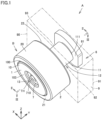
- the outer ring 2 includes an outer circumferential surface 20, a fourth end surface 21 connected to one end edge of the outer circumferential surface 20, and a fifth end surface 22 connected to another end edge of the outer circumferential surface 20.
- the fourth end surface 21 and the fifth end surface 22 are parallel.
- FIG. 5 is a schematic perspective view of the fixing element 6 in Embodiment 1 of the present disclosure, as viewed in a first direction.
- FIG. 6 is a schematic perspective view of the fixing element 6 of FIG. 5 , as viewed in a second direction which is opposite to the first direction.
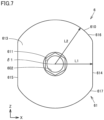
- FIG. 7 is a schematic view of the fixing element 6 of FIG. 5 , as viewed in a direction facing a tenth end surface 613 of a plate-shaped portion 61.
- FIG. 8 is a schematic cross-sectional view of the fixing element 6 of FIG. 5 , as cut in a plane including a central axis ⁇ 1 of a cylindrical portion 60.
- the eighth end surface 601 faces in the same direction as the insertion direction when the cylindrical portion 60 is inserted into the through hole TH.
- the fourth inner circumferential surface 602 has a threaded groove formed thereon. That is, the cylindrical portion 60 includes the threaded groove on the fourth inner circumferential surface 602.
- the plate-shaped portion 61 is arranged to be orthogonal to a central axis ⁇ 1 of the cylindrical portion 60.
- the plate-shaped portion 61 includes an outer circumferential surface 610, an inner circumferential surface 611, a ninth end surface 612 connecting the outer circumferential surface 610 to the circular arc-shaped portion 62, and a tenth end surface 613 connecting the outer circumferential surface 610 to the inner circumferential surface 611.
- the outer circumferential surface 610 includes a pair of flat surface portions 614, 615 which are flat-shaped and arranged parallel to each other, and a pair of circular arc surface portions 616, 617 which are circular arc-shaped and connecting the flat surface portion 614 to the flat surface portion 615. As shown in FIG.
- the inner circumferential surface 611 has a regular hexagonal cylindrical shape. Rotation of the fixing element 6 with the central axis ⁇ 1 of the cylindrical portion 60 as the axis of rotation can be suppressed by fitting a hexagon socket screw key or the like to the inside of the cylindrical portion 60 so as to contact the inner circumferential surface 611.
- the follower bearing B and the fixing element 6 can be fastened together by coupling between the threaded groove of the cylindrical portion 60 inserted into the through hole TH and the thread of the body portion 70 inserted into the through hole TH in the state where the plate-shaped portion 61 of the fixing element 6 is located on one side in the direction along the central axis ⁇ as viewed from the through hole TH and where the head portion 71 of the bolt 7 is located on the other side in the direction along the central axis ⁇ as viewed from the through hole TH.
- the shaft member 1 includes the outer circumferential surface 12 including the annular first raceway surface P1 having the central axis ⁇ , and the inner wall surface 13 defining the through hole TH including the central axis ⁇ .
- the through hole TH has a diameter that is 40% or more of an outside diameter of a portion of the shaft member 1 having a smallest outside diameter.
- the above formed body is prepared by, for example, forming it by cold forging and then adjusting the shape by turning. Forming the formed body by cold forging enables grain flows in the shaft member 1 to be continuous, thereby ensuring the strength of the shaft member 1.
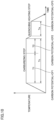
- the temperature is maintained at a temperature not lower than the A1 point of the steel and not higher than 900°C for a predetermined carburizing time Tc.
- the carburizing time Tc is, for example, 160 minutes.
- the carbon potential in the atmosphere is maintained at a predetermined value CP1 (for example, 1.1%) for a first time T1 (for example, 130 minutes) in the carburizing time Tc.
- the carbon potential in the atmosphere is maintained at a predetermined value CP2 (for example, 0.9%) lower than the value CP1 for a second time T2 (for example, 30 minutes) in the carburizing time Tc.
- step ST5 the formed piece that has been tempered in step ST4 is finished by grinding or the like.
- the outer circumferential surface including the first raceway surface P1 of the large diameter portion 10 of the shaft member 1 is subjected to grinding to thereby remove an abnormal carburized layer (intergranular oxidation layer) generated in the carburizing treatment.
- the outer circumferential surface of the small diameter portion 11 corresponding to the first end portion 11a is not subjected to grinding.
- an abnormal carburized layer exists in the region including the outer circumferential surface corresponding to the first end portion 11a.
- the shaft member 1 is produced through the processes in steps ST1 to ST5 as described above.
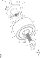
- FIG. 11 is a schematic perspective view of a follower bearing module A in Embodiment 2 of the present disclosure.
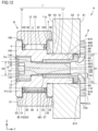
- FIG. 12 is a schematic view of a cross section indicated by IV-IV in FIG. 11 .
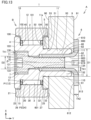
- FIG. 13 is a schematic view of a cross section indicated by V-V in FIG. 11 .
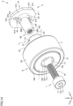
- FIG. 14 is a schematic exploded perspective view of the follower bearing module A shown in FIG. 11 .
- the mounted member 9 is indicated by long dashed short dashed lines.
- the central axis ⁇ is indicated by a long dashed short dashed line.
- the illustration of the mounted member 9 is omitted.
- the small diameter portion 11 of the shaft member 1 further includes notches 112 and 113 formed so as to cut off portions of corners formed by the outer circumferential surface 110 and the third end surface 111.
- the notches 112 and 113 are arranged 180 degrees apart from each other in a circumferential direction of the small diameter portion 11.
- the notches 112 and 113 each have a rectangular contour, whether viewed from the axial direction or from the radial direction.
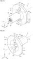
- FIG. 15 is a schematic perspective view of the fixing element 6 in Embodiment 2 of the present disclosure, as viewed in a first direction.
- FIG. 16 is a schematic perspective view of the fixing element 6 of FIG. 15 , as viewed in a second direction which is opposite to the first direction.
- FIG. 17 is a schematic view of the fixing element 6 of FIG. 15 , as viewed in a direction facing the tenth end surface 613 of the plate-shaped portion 61.
- the fixing element 6 further includes protruding portions 63 and 64 that protrude radially outward of the cylindrical portion 60 on the outer circumferential surface 600 of the cylindrical portion 60 from portions near the plate-shaped portion 61.
- the protruding portion 63 is fitted into the notch 112 of the small diameter portion 11 of the shaft member 1.
- the protruding portion 63 interferes with the inner wall surface of the notch 112 to thereby suppress the rotation of the shaft member 1 with the central axis ⁇ or an axis parallel to the central axis ⁇ as the axis of rotation.
- the protruding portion 64 is fitted into the notch 113 of the small diameter portion 11.
- the cylindrical portion 60 further includes a fifth inner circumferential surface 603 connected to the fourth inner circumferential surface 602.
- the fifth inner circumferential surface 603 has a regular hexagonal cylindrical shape. Rotation of the fixing element 6 with the central axis ⁇ 1 of the cylindrical portion 60 as the axis of rotation can be suppressed by fitting a hexagon socket screw key or the like to the inside of the cylindrical portion 60 so as to contact the fifth inner circumferential surface 603.
- the inner circumferential surface 611 of the plate-shaped portion 61 has a circular arc shape connecting the tenth end surface 613 of the plate-shaped portion 61 to the fifth inner circumferential surface 603 of the cylindrical portion 60.
- the plate-shaped portion 61 has two plate-shaped portion through holes 618 and 619 formed therein.
- the plate-shaped portion through holes 618 and 619 are arranged 180 degrees apart from each other in a circumferential direction of the cylindrical portion 60.
- the plate-shaped portion through holes 618 and 619 are arranged at positions farther than the protruding portions 63 and 64 with respect to the central axis ⁇ 1 of the cylindrical portion 60.
- the protruding portions 63, 64 can be easily formed by deforming portions of the plate-shaped portion 61 utilizing the plate-shaped portion through holes 618, 619.
- the small diameter portion 11 there may be one notch in the small diameter portion 11 and one protruding portion in the fixing element 6, or there may be three or more of each, as required.
- the number of notches in the small diameter portion 11 may be greater than the number of protruding portions in the fixing element 6.
- the method of producing the shaft member 1 (inner member) of the follower bearing B in Embodiment 2 is identical to the above-described method of producing the shaft member 1 (inner member) in Embodiment 1.
- FIG. 18 is a diagram showing an example of the prior austenite grains in the carburized layer of the shaft member 1 produced according to the method of producing the shaft member 1 of the present disclosure.
- the example shown in FIG. 18 was obtained by heating to a temperature of 860°C in the carburizing step.
- the grain size number of the prior austenite grains is 9.5.
- FIG. 19 is a diagram showing a comparative example of the prior austenite grains in a carburized layer of a shaft member 1.
- the example shown in FIG. 19 was obtained by heating to a temperature of 930°C in the carburizing step.
- the grain size number of the prior austenite grains is 7.8.
- a carburized layer having the prior austenite grains with a grain size number of 8.6 or more was obtained by heating the formed body to a temperature not lower than the A1 point of the steel and not higher than 900°C in a carburizing atmosphere in the carburizing step.
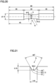
- FIG. 20 is a schematic view of a test specimen used in a rotating bending fatigue test in Example 2.
- FIG. 21 is an enlarged view of a notch N in the test specimen of FIG. 20 .
- the numbers indicate dimensions (in mm).
- ⁇ means diameter.
- R means radius of curvature.
- a rotating bending fatigue test was performed on the basis of JIS Z 2274 using the test specimens as shown in FIG. 20 .
- the load frequency was 50 kHz.
- the test was terminated if the test specimen did not break until the number of revolutions of the test specimen had reached 10 7 times from the beginning of the test.
- test specimen one composed of SCM415 specified in JIS G 4053 was prepared.
- Three types of test specimens were prepared, including one heated to a temperature of 860°C in a carburizing atmosphere, one heated to a temperature of 900°C in the carburizing atmosphere, and one heated to a temperature of 930°C in the carburizing atmosphere.
- the test specimens were all fabricated by forming a carburized layer and then performing the quenching and tempering steps, as in the above-described method of producing the shaft member 1.
- the notch N has a surface in the state not subjected to grinding (the state in which the abnormal carburized layer exists).
- the results obtained from the rotating bending fatigue test performed on these test specimens were applied to the regression model described in the Standard Evaluation Method of Fatigue Reliability for Metallic Materials (JSMS-SD-6-02) of the Society of Materials Science, Japan, to obtain S-N curves.
- FIG. 22 is a diagram showing the S-N curves obtained from the rotating bending fatigue test in Example 2.
- the vertical axis shows the stress amplitude on a normal scale.
- the horizontal axis shows the number of cycles on a logarithmic scale.
- the arrows indicate the termination of the test.
- the circles indicate data points for the test specimens heated to the temperature of 860°C in the carburizing atmosphere
- the diamonds indicate data points for the test specimens heated to the temperature of 900°C in the carburizing atmosphere
- the triangles indicate data points for the test specimens heated to the temperature of 930°C in the carburizing atmosphere.
- the bold line shows the S-N curve for the test specimens heated to the temperature of 860°C in the carburizing atmosphere
- the dashed line shows the S-N curve for the test specimens heated to the temperature of 900°C in the carburizing atmosphere
- the long dashed short dashed line shows the S-N curve for the test specimens heated to the temperature of 930°C in the carburizing atmosphere.
- the test specimens heated to the temperature of 860°C in the carburizing atmosphere had a fatigue limit of about 547 MPa
- the test specimens heated to the temperature of 900°C in the carburizing atmosphere had a fatigue limit of about 529 MPa
- the test specimens heated to the temperature of 930°C in the carburizing atmosphere had a fatigue limit of about 417 MPa.
- FIG. 23 is a diagram showing an example of the prior austenite grains in a carburized layer of a test specimen heated to a temperature of 860°C in a carburizing atmosphere. In the example shown in FIG. 23 , the grain size number of the prior austenite grains is 9.6.
- FIG. 24 is a diagram showing an example of the prior austenite grains in a carburized layer of a test specimen heated to a temperature of 900°C in a carburizing atmosphere. In the example shown in FIG. 24 , the grain size number of the prior austenite grains is 8.6.
- FIG. 25 is a diagram showing an example of the prior austenite grains in a carburized layer of a test specimen heated to a temperature of 930°C in a carburizing atmosphere. In the example shown in FIG. 25 , the grain size number of the prior austenite grains is 8.0.
- FIG. 26 is a diagram illustrating a relationship between the fatigue limit and the grain size number of the prior austenite grains.
- the vertical axis represents the fatigue limit.
- the horizontal axis represents the grain size number of the prior austenite grains.
- the dashed line in FIG. 26 is an approximate curve expressing the transition of the fatigue limit with respect to the grain size number of the prior austenite grains. The relationship between the fatigue limit and the grain size number of the prior austenite grains was obtained by first obtaining a relationship between the fatigue limits obtained from the S-N curves in FIG.
- 1 shaft member (inner member); 2: outer ring; 3: roller (rolling element); 4: retainer; 5: side plate; 6: fixing element; 7: bolt; 9: mounted member; 10: large diameter portion; 11: small diameter portion; 11a: first end portion; 11b: portion; 12: outer circumferential surface; 13: inner wall surface; 20: outer circumferential surface; 21: fourth end surface; 22: fifth end surface; 23: first inner circumferential surface; 24: second inner circumferential surface; 25: third inner circumferential surface; 26: fourth stepped surface; 27: fifth stepped surface; 30: outer circumferential surface; 31: end surface; 32: end surface; 40: pocket; 50: outer circumferential surface; 51: inner circumferential surface; 52: sixth end surface; 53: seventh end surface; 60: cylindrical portion; 61: plate-shaped portion; 62: circular arc-shaped portion; 63: protruding portion; 64: protruding portion; 70: body portion; 71: head portion; 90: first surface; 91:
Landscapes
- Engineering & Computer Science (AREA)
- General Engineering & Computer Science (AREA)
- Mechanical Engineering (AREA)
- Mounting Of Bearings Or Others (AREA)
- Rolling Contact Bearings (AREA)
- Gears, Cams (AREA)
Applications Claiming Priority (2)
| Application Number | Priority Date | Filing Date | Title |
|---|---|---|---|
| JP2022097876 | 2022-06-17 | ||
| PCT/JP2023/019182 WO2023243332A1 (fr) | 2022-06-17 | 2023-05-23 | Palier suiveur, module de palier suiveur, et procédé de fabrication d'élément interne pour palier suiveur |
Publications (2)
| Publication Number | Publication Date |
|---|---|
| EP4534865A1 true EP4534865A1 (fr) | 2025-04-09 |
| EP4534865A4 EP4534865A4 (fr) | 2025-09-17 |
Family
ID=89191073
Family Applications (2)
| Application Number | Title | Priority Date | Filing Date |
|---|---|---|---|
| EP23823632.7A Pending EP4534865A4 (fr) | 2022-06-17 | 2023-05-23 | Palier suiveur, module de palier suiveur, et procédé de fabrication d'élément interne pour palier suiveur |
| EP23823631.9A Pending EP4477905A4 (fr) | 2022-06-17 | 2023-05-23 | Module de palier suiveur |
Family Applications After (1)
| Application Number | Title | Priority Date | Filing Date |
|---|---|---|---|
| EP23823631.9A Pending EP4477905A4 (fr) | 2022-06-17 | 2023-05-23 | Module de palier suiveur |
Country Status (5)
| Country | Link |
|---|---|
| US (1) | US12066089B1 (fr) |
| EP (2) | EP4534865A4 (fr) |
| JP (2) | JP7410357B1 (fr) |
| CN (2) | CN119213231A (fr) |
| WO (2) | WO2023243332A1 (fr) |
Family Cites Families (20)
| Publication number | Priority date | Publication date | Assignee | Title |
|---|---|---|---|---|
| US3602150A (en) * | 1969-05-01 | 1971-08-31 | Frost & Son C L | Suspended trolley conveyor system |
| GB1202190A (en) * | 1969-06-17 | 1970-08-12 | Roller Bearing Co Of America | An eccentrically adjustable roller |
| US4113327A (en) * | 1976-12-29 | 1978-09-12 | Roller Bearing Company Of America | Combination seal and thrust washer for anti-friction bearings |
| US4798149A (en) * | 1982-12-02 | 1989-01-17 | Florkey's Conveyor Service, Inc. | Wheel lock assembly |
| DE69004477T2 (de) * | 1989-01-25 | 1994-05-11 | Skb Fabrique De Roulements Bie | Rolle. |
| US5724861A (en) | 1996-03-27 | 1998-03-10 | Emerson Electric Company | Cam follower mounting assembly and method |
| JP4603643B2 (ja) | 1999-06-08 | 2010-12-22 | 株式会社三共製作所 | カムフォロアの固定構造 |
| JP2002194438A (ja) * | 2000-12-22 | 2002-07-10 | Nsk Ltd | 転がり軸受 |
| ES2259176T3 (es) * | 2002-10-17 | 2006-09-16 | Ntn Corporation | Seguidor de leva de rodillo para un motor. |
| DE102005060531A1 (de) * | 2005-12-17 | 2007-07-19 | Schaeffler Kg | Befestigung einer Umlenkrolle |
| JP4812571B2 (ja) * | 2006-06-05 | 2011-11-09 | 日本トムソン株式会社 | カムフォロア |
| JP2008020003A (ja) * | 2006-07-13 | 2008-01-31 | Ntn Corp | 軌道部材の製造方法、動弁装置の製造方法および軌道部材 |
| JP2008063603A (ja) * | 2006-09-05 | 2008-03-21 | Ntn Corp | 軌道部材の製造方法、動弁装置の製造方法および軌道部材 |
| JP2008064159A (ja) * | 2006-09-05 | 2008-03-21 | Ntn Corp | 軌道部材の製造方法、動弁装置の製造方法および軌道部材 |
| JP5489111B2 (ja) * | 2009-03-25 | 2014-05-14 | Ntn株式会社 | 軸受部品、転がり軸受および軸受部品の製造方法 |
| DE102018220323B3 (de) * | 2018-11-27 | 2019-11-21 | Heidelberger Druckmaschinen Ag | Rollenlagerung in einer Druckmaschine |
| JP7318903B2 (ja) | 2019-02-05 | 2023-08-01 | テクノダイナミックス株式会社 | カム装置 |
| JP2021042837A (ja) * | 2019-09-13 | 2021-03-18 | 日本トムソン株式会社 | 旋回テーブル用軸受および旋回テーブル |
| JP7442120B2 (ja) * | 2019-09-19 | 2024-03-04 | 日本トムソン株式会社 | 潤滑剤組成物及びそれを封入した軸受 |
| JP7575936B2 (ja) | 2020-12-21 | 2024-10-30 | 東芝ライフスタイル株式会社 | 冷蔵庫システム |
-
2023
- 2023-05-23 JP JP2023557090A patent/JP7410357B1/ja active Active
- 2023-05-23 CN CN202380040742.4A patent/CN119213231A/zh active Pending
- 2023-05-23 WO PCT/JP2023/019182 patent/WO2023243332A1/fr not_active Ceased
- 2023-05-23 EP EP23823632.7A patent/EP4534865A4/fr active Pending
- 2023-05-23 WO PCT/JP2023/019181 patent/WO2023243331A1/fr not_active Ceased
- 2023-05-23 US US18/580,233 patent/US12066089B1/en active Active
- 2023-05-23 CN CN202380012582.2A patent/CN117642562B/zh active Active
- 2023-05-23 EP EP23823631.9A patent/EP4477905A4/fr active Pending
- 2023-05-23 JP JP2024528437A patent/JPWO2023243332A1/ja active Pending
Also Published As
| Publication number | Publication date |
|---|---|
| CN119213231A (zh) | 2024-12-27 |
| EP4477905A4 (fr) | 2025-07-02 |
| JPWO2023243331A1 (fr) | 2023-12-21 |
| CN117642562B (zh) | 2024-08-09 |
| EP4477905A1 (fr) | 2024-12-18 |
| US20240263694A1 (en) | 2024-08-08 |
| JP7410357B1 (ja) | 2024-01-09 |
| CN117642562A (zh) | 2024-03-01 |
| US12066089B1 (en) | 2024-08-20 |
| WO2023243331A1 (fr) | 2023-12-21 |
| EP4534865A4 (fr) | 2025-09-17 |
| JPWO2023243332A1 (fr) | 2023-12-21 |
| WO2023243332A1 (fr) | 2023-12-21 |
Similar Documents
| Publication | Publication Date | Title |
|---|---|---|
| US9346097B2 (en) | Process for manufacturing rolling contact member, process for manufacturing rolling bearing, raceway member of rolling bearing and rolling bearing | |
| CN101529105B (zh) | 摆动轴承用外圈、摆动轴承用保持器、摆动轴承及气压盘式制动器装置 | |
| WO2008050671A1 (fr) | Bague externe pour support oscillant, dispositif de retenue pour support oscillant, support oscillant et frein à disque à air | |
| CN103975081B (zh) | 机器零件、滚动轴承、锥形滚柱轴承以及制造机器零件的方法 | |
| EP2444200B1 (fr) | Procédé pour fabriquer un ressort hélicoïdal | |
| JP5045491B2 (ja) | 大型転がり軸受 | |
| WO2019189087A1 (fr) | Pièce de support | |
| US20220411891A1 (en) | Rolling bearing | |
| EP3315619A1 (fr) | Procédé de fabrication d'un pièce de roulement | |
| CN100570167C (zh) | 机械元件及其制造方法 | |
| EP3591089A1 (fr) | Élément de palier, palier à roulement et procédé de fabrication d'élément de palier | |
| WO2022202922A1 (fr) | Galet de roulement et arbre | |
| EP1961584A1 (fr) | Dispositif de roulement pour roue | |
| EP4534865A1 (fr) | Palier suiveur, module de palier suiveur, et procédé de fabrication d'élément interne pour palier suiveur | |
| EP4394059A1 (fr) | Composant mécanique et palier à roulement | |
| JP5147259B2 (ja) | 車輪用軸受装置の製造方法 | |
| EP4039833A1 (fr) | Composant de palier | |
| CN105026591B (zh) | 非调质型软氮化部件 | |
| US20060130333A1 (en) | Method of forming bearing ring resistant to season cracking | |
| WO2019065622A1 (fr) | Piece de roulement et roulement | |
| JPH10184701A (ja) | 転がり軸受 | |
| JP2007182609A (ja) | 車輪軸受装置用転動部材の製造方法、車輪軸受装置用転動部材および車輪軸受装置 | |
| JP2005098320A (ja) | 車輪支持用軸受装置 | |
| US10077484B2 (en) | Method for producing a planetary gear shaft having increased hardness | |
| JP2023068856A (ja) | 転がり軸受 |
Legal Events
| Date | Code | Title | Description |
|---|---|---|---|
| STAA | Information on the status of an ep patent application or granted ep patent |
Free format text: STATUS: THE INTERNATIONAL PUBLICATION HAS BEEN MADE |
|
| PUAI | Public reference made under article 153(3) epc to a published international application that has entered the european phase |
Free format text: ORIGINAL CODE: 0009012 |
|
| STAA | Information on the status of an ep patent application or granted ep patent |
Free format text: STATUS: REQUEST FOR EXAMINATION WAS MADE |
|
| 17P | Request for examination filed |
Effective date: 20241230 |
|
| AK | Designated contracting states |
Kind code of ref document: A1 Designated state(s): AL AT BE BG CH CY CZ DE DK EE ES FI FR GB GR HR HU IE IS IT LI LT LU LV MC ME MK MT NL NO PL PT RO RS SE SI SK SM TR |
|
| A4 | Supplementary search report drawn up and despatched |
Effective date: 20250818 |
|
| RIC1 | Information provided on ipc code assigned before grant |
Ipc: F16C 19/26 20060101AFI20250811BHEP Ipc: F16C 33/62 20060101ALI20250811BHEP |
|
| DAV | Request for validation of the european patent (deleted) | ||
| DAX | Request for extension of the european patent (deleted) |