EP4534875A1 - Mechanisches werkzeug - Google Patents
Mechanisches werkzeug Download PDFInfo
- Publication number
- EP4534875A1 EP4534875A1 EP23811815.2A EP23811815A EP4534875A1 EP 4534875 A1 EP4534875 A1 EP 4534875A1 EP 23811815 A EP23811815 A EP 23811815A EP 4534875 A1 EP4534875 A1 EP 4534875A1
- Authority
- EP
- European Patent Office
- Prior art keywords
- seal ring
- rotating
- axial
- casing
- back surface
- Prior art date
- Legal status (The legal status is an assumption and is not a legal conclusion. Google has not performed a legal analysis and makes no representation as to the accuracy of the status listed.)
- Pending
Links
Images



Classifications
-
- F—MECHANICAL ENGINEERING; LIGHTING; HEATING; WEAPONS; BLASTING
- F16—ENGINEERING ELEMENTS AND UNITS; GENERAL MEASURES FOR PRODUCING AND MAINTAINING EFFECTIVE FUNCTIONING OF MACHINES OR INSTALLATIONS; THERMAL INSULATION IN GENERAL
- F16J—PISTONS; CYLINDERS; SEALINGS
- F16J15/00—Sealings
- F16J15/16—Sealings between relatively-moving surfaces
- F16J15/34—Sealings between relatively-moving surfaces with slip-ring pressed against a more or less radial face on one member
- F16J15/3464—Mounting of the seal
-
- F—MECHANICAL ENGINEERING; LIGHTING; HEATING; WEAPONS; BLASTING
- F16—ENGINEERING ELEMENTS AND UNITS; GENERAL MEASURES FOR PRODUCING AND MAINTAINING EFFECTIVE FUNCTIONING OF MACHINES OR INSTALLATIONS; THERMAL INSULATION IN GENERAL
- F16J—PISTONS; CYLINDERS; SEALINGS
- F16J15/00—Sealings
- F16J15/16—Sealings between relatively-moving surfaces
- F16J15/34—Sealings between relatively-moving surfaces with slip-ring pressed against a more or less radial face on one member
- F16J15/38—Sealings between relatively-moving surfaces with slip-ring pressed against a more or less radial face on one member sealed by a packing
Definitions
- the present invention relates to a mechanical seal, for example, a mechanical seal that seals a rotating shaft.
- a mechanical seal is mounted and used between a housing of a fluid device and a rotating shaft disposed to penetrate through the housing, and has the function of reducing friction occurring between sliding surfaces and preventing the leakage of a sealed fluid by allowing sliding contact in a circumferential direction between the sliding surface of a stationary seal ring fixed to a stationary-side casing attached to the housing and the sliding surface of a rotating seal ring that is fixed to a rotating-side casing attached to the rotating shaft and that rotates.
- a seal member is disposed between the stationary seal ring and the stationary-side casing, and sealability between the stationary seal ring and the stationary-side casing is ensured.
- the stationary seal ring is disposed to be movable in an axial direction with respect to the stationary-side casing, and is biased toward a rotating seal ring side by biasing means.
- the rotating seal ring is press-fitted into the rotating-side casing with a cup gasket interposed therebetween.
- the rotating-side casing includes an axial wall extending in a tubular shape in the axial direction; a radial wall extending in an annular shape in a radially inward direction from a back surface-side end portion of the axial wall; and a fixed wall extending in the axial direction from a radially inner end portion of the radial wall and fixed to the rotating shaft.
- the cup gasket includes an axial portion sandwiched between an outer peripheral surface of the rotating seal ring and an inner peripheral surface of the axial wall of the rotating-side casing, and a radial portion sandwiched between a back surface of the rotating seal ring and a front surface of the radial wall of the rotating-side casing. Accordingly, sealability and fixing force between the rotating-side casing and the rotating seal ring are ensured.
- Patent Citation 1 WO 2019/163726 A (Page 5, FIG. 1 )
- the present invention has been made in view of such problems, and an object of the present invention is to provide a mechanical seal capable of appropriately setting the surface pressure between sliding surfaces.
- a mechanical seal is a mechanical seal including a seal ring held by a casing with an elastic body interposed between the seal ring and the casing, wherein the casing includes an axial wall extending in an axial direction along a peripheral surface of the seal ring, and a radial wall extending in a radial direction along a back surface of the seal ring, the elastic body includes an axial portion sandwiched between the peripheral surface of the seal ring and the axial wall of the casing, and a radial portion sandwiched between the back surface of the seal ring and the radial wall of the casing, and the elastic body further includes a tapered portion which is formed between a peripheral surface of the axial portion and a back surface of the radial portion and which extends from the axial portion to a back surface position of the seal ring such that the tapered portion overlaps with the back surface of the seal ring in an axial directional view.
- the elastic body escapes into a gap between the tapered portion and the casing, so that the seal ring can be properly installed in a state where the back surface of the radial portion is brought into contact with the radial wall, and the surface pressure between sliding surfaces can be appropriately set.
- the tapered portion includes a flat surface. According to this preferable configuration, the tapered portion easily comes into smooth contact with the radial wall of the casing.
- the tapered portion includes two tapered surfaces. According to this preferable configuration, while a gap between the casing and the elastic body is reduced, the elastic body is efficiently elastically deformed in the gap.
- the tapered portion has an inner diameter side end which is positioned between the axial portion and a radial center of the seal ring in a radial width of the seal ring. According to this preferable configuration, the gap between the casing and the elastic body can be reduced.
- a corner portion of the seal ring covered by the elastic body is chamfered. According to this preferable configuration, a part of the elastic body that is elastically deformed is disposed in a gap between the corner portion of the seal ring and the elastic body.
- the corner portion is chamfered to a larger extent than other corner portions of the seal ring. According to this preferable configuration, the gap in which a part of the elastic body that is elastically deformed is disposed can be ensured to a large extent.
- a cutout portion is formed at a tip portion of the peripheral surface of the axial portion. According to this preferable configuration, a part of the elastic body that is elastically deformed is disposed in a gap between the cutout portion and the casing.
- FIGS. 1 to 5 A mechanical seal according to a first embodiment of the present invention will be described with reference to FIGS. 1 to 5 .
- the left side of the drawing sheet and the right side of the drawing sheet of FIG. 1 will be described as a left side and a right side, respectively.
- a mechanical seal 1 is an inside mechanical seal that seals a sealed fluid F attempting to leak from a radially outer side toward a radially inner side.
- a space on the radially inner side of a stationary seal ring 11 and a rotating seal ring 21 will be described as an atmosphere A side
- a space on the radially outer side of the stationary seal ring 11 and the rotating seal ring 21 will be described as a sealed fluid F side.
- the stationary-side element S mainly includes a stationary-side casing 10 fixed to a housing 3; the stationary seal ring 11 having an annular shape and provided to be non-rotatable and movable in an axial direction inside the casing 10; a bellows 12 that seals a gap between the casing 10 and the stationary seal ring 11; and a spring 13 that biases the stationary seal ring 11 toward the rotating seal ring 21 to be described later.
- the stationary-side casing 10 mainly includes a first portion 10a having a tubular shape and extending in the axial direction along an inner peripheral surface of the housing 3; a second portion 10b having a circular annular shape and extending in a radially inward direction from a right end portion of the first portion 10a; and a third portion 10c having a tubular shape and extending from a radially inner end portion of the second portion 10b to the left side.
- the stationary seal ring 11 includes a base portion 11a; a protrusion 11b having an annular shape and protruding in the axial direction from the radially inner side and a left surface side of the base portion 11a; and a protrusion 11c having an annular shape and protruding in the axial direction from the radially inner side and a right surface side of the base portion 11a.
- the rotating-side element R mainly includes a rotating-side casing 20 fixed to a rotating shaft 2; the rotating seal ring 21 disposed inside the casing 20; and a cup gasket 22 as an elastic body disposed in a compressed state between the casing 20 and the rotating seal ring 21.
- the rotating-side casing 20 includes a first portion 20a as an axial wall having a cylindrical shape and extending in the axial direction; a second portion 20b as a radial wall having a circular annular shape and extending in the radially inward direction from a left end portion of the first portion 20a; and a third portion 20c having a cylindrical shape and extending from a radially inner end portion of the second portion 20b to the right side along the rotating shaft 2.
- the first portion 20a and the second portion 20b form substantially 90 degrees.
- the rotating seal ring 21 has a rectangular cross section, and a right surface thereof, namely, a front surface of the rotating seal ring 21 is a flat sliding surface 21a.
- a front surface of the rotating seal ring 21 is a flat sliding surface 21a.
- the right side and the left side of the rotating seal ring 21 may be referred to as a front surface side and a back surface side, respectively.
- a corner portion 21b on the radially outer side of a left surface namely, a back surface of the rotating seal ring 21, a corner portion 21c on the radially outer side of the front surface, a corner portion 21d on the radially inner side of the front surface, and a corner portion 21e on the radially inner side of the back surface are chamfered.
- the corner portion 21b on the radially outer side of the back surface is chamfered to a larger extent than the other corner portions 21c to 21e.
- a back surface 21f of the rotating seal ring 21 which is a surface on the back surface side excluding the corner portions 21b and 21e is a flat surface in the present embodiment.
- the cup gasket 22 is an annular member made of an elastically deformable synthetic resin, and has an L-shaped cross section and includes an axial portion 221 having a tubular shape and extending in the axial direction, and a radial portion 222 having a circular annular shape and extending in the radially inward direction from a back surface-side end portion of the axial portion 221.
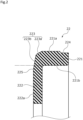
- a tapered portion 223 is formed at a corner portion on the radially outer side of a back surface of the cup gasket 22 to taper toward the back surface side.
- the tapered portion 223 includes a first inclined surface 223a as a flat tapered surface that tapers from an outer peripheral surface 221a of the axial portion 221 toward the back surface side, and a second inclined surface 223b as a flat tapered surface that further tapers from a back surface-side end portion of the first inclined surface 223a toward a back surface 222a of the radial portion 222.
- a boundary portion 225 between the second inclined surface 223b and the back surface 222a of the radial portion 222 is disposed on the radially inner side of an inner peripheral surface 221b of the axial portion 221.
- the second inclined surface 223b extends to the back surface position of the back surface 21f of the rotating seal ring 21, namely, to a position where the second inclined surface 223b overlaps the back surface 21f of the rotating seal ring 21 in the axial direction.
- the boundary portion 225 is disposed on the radially outer side (namely, on an axial portion 221 side) of a radial center 21g of the rotating seal ring 21 at the back surface position of the back surface 21f of the rotating seal ring 21.
- a portion of the back surface 21f of the rotating seal ring 21, which is located on an axis passing through the radial center 21g of the rotating seal ring 21, may be simply referred to as a "radial center of the back surface 21f of the rotating seal ring 21".
- a cutout portion 224 is formed at a tip portion on the front surface side of the axial portion 221.
- the cutout portion 224 is formed in an annular shape to be open on the radially outer side and the front surface side.
- the cutout portion 224 is not limited to an annular shape, and the cutout portions 224 may be provided at a plurality of locations in a circumferential direction.
- an inner diameter of the rotating-side casing 20 and an outer diameter of the cup gasket 22 are substantially the same.
- the outer peripheral surface 221a of the axial portion 221 is in surface contact with an inner peripheral surface of the first portion 20a of the rotating-side casing 20
- the back surface 222a of the radial portion 222 is in surface contact with a front surface of the second portion 20b of the rotating-side casing 20.
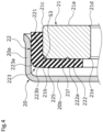
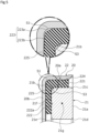
- a gap S1 is formed between the tapered portion 223 and a corner portion on the radially inner side of the rotating-side casing 20.
- a gap S2 is formed between the cutout portion 224 and the first portion 20a.
- an outer diameter of the rotating seal ring 21 is slightly larger than an inner diameter of the cup gasket 22.
- the cup gasket 22 is press-fitted from the front surface side of the rotating-side casing 20 toward the back surface side. Since the axial portion 221 is compressed in the radial direction between the rotating seal ring 21 and the first portion 20a of the rotating-side casing 20, the axial portion 221 is elastically deformed to bulge in the axial direction.
- the tapered portion 223 of the axial portion 221 bulges toward the back surface side.
- the second inclined surface 223b is located on the front surface side of the back surface 222a of the radial portion 222 and the boundary portion 225.
- the first inclined surface 223a of the tapered portion 223 bulges in the radially outward direction, but is located on the radially inner side of the inner peripheral surface of the first portion 20a of the rotating-side casing 20.
- a gap S3 is formed between a corner portion on the radially inner side between the axial portion 221 and the radial portion 222 forming substantially 90 degrees and the corner portion 21b of the rotating seal ring 21.
- a part of the cup gasket 22 that elastically deforms can escape into the gap S3, and the gap S3 becomes smaller than before the cup gasket 22 is press-fitted into the rotating-side casing 20.
- the boundary portion 225 is disposed at a back surface position on the axial portion 221 side of the radial center of the back surface 21f of the rotating seal ring 21.
- the radially outer side of the second inclined surface 223b of the tapered portion 223 is slightly separated from the second portion 20b of the rotating-side casing 20 toward the front surface side.
- first inclined surface 223a of the tapered portion 223 is slightly separated from the radially inner side of the first portion 20a of the rotating-side casing 20.
- the gap S1 becomes smaller than in the state illustrated in FIG. 3 .
- the vicinity of the cutout portion 224 of the axial portion 221 bulges toward the radially outer side to fill the gap S2.
- the tapered portion 223 is formed in the cup gasket 22 to extend to the back surface position of the rotating seal ring 21 from the outer peripheral surface 221a of the axial portion 221 to the back surface 222a of the radial portion 222. Accordingly, when the rotating seal ring 21 is press-fitted into the rotating-side casing 20, the tapered portion 223 can escape into the gap S1 between the tapered portion 223 and the rotating-side casing 20, so that the rotating seal ring 21 can be properly installed in a state where the back surface 222a of the radial portion 222 is brought into contact with the second portion 20b. Therefore, the elastic force of the cup gasket 22 does not act on the surface pressure between the sliding surfaces 11d and 21a, and an appropriate surface pressure can be achieved by the biasing force of the spring 13.
- the boundary portion 225 is disposed at a back surface position on the axial portion 221 side of the radial center of the back surface 21f of the rotating seal ring 21, the back surface 222a of the radial portion 222 that comes into contact with the second portion 20b of the rotating-side casing 20 can be ensured to a large extent. Namely, the gap S1 can be reduced.
- the cutout portion 224 is formed at the tip portion on the front surface side of the axial portion 221, a part of the cup gasket 22 that elastically deforms can escape into the gap S2 between the cutout portion 224 and the rotating-side casing 20.
Landscapes
- Engineering & Computer Science (AREA)
- General Engineering & Computer Science (AREA)
- Mechanical Engineering (AREA)
- Mechanical Sealing (AREA)
Applications Claiming Priority (2)
| Application Number | Priority Date | Filing Date | Title |
|---|---|---|---|
| JP2022084967 | 2022-05-25 | ||
| PCT/JP2023/019171 WO2023228943A1 (ja) | 2022-05-25 | 2023-05-23 | メカニカルシール |
Publications (2)
| Publication Number | Publication Date |
|---|---|
| EP4534875A1 true EP4534875A1 (de) | 2025-04-09 |
| EP4534875A4 EP4534875A4 (de) | 2026-05-06 |
Family
ID=88919384
Family Applications (1)
| Application Number | Title | Priority Date | Filing Date |
|---|---|---|---|
| EP23811815.2A Pending EP4534875A4 (de) | 2022-05-25 | 2023-05-23 | Mechanisches werkzeug |
Country Status (4)
| Country | Link |
|---|---|
| EP (1) | EP4534875A4 (de) |
| JP (1) | JPWO2023228943A1 (de) |
| CN (1) | CN119301389A (de) |
| WO (1) | WO2023228943A1 (de) |
Family Cites Families (5)
| Publication number | Priority date | Publication date | Assignee | Title |
|---|---|---|---|---|
| US5676382A (en) * | 1995-06-06 | 1997-10-14 | Freudenberg Nok General Partnership | Mechanical face seal assembly including a gasket |
| JP2000074226A (ja) * | 1998-08-27 | 2000-03-14 | Eagle Ind Co Ltd | メカニカルシール |
| CN104379974B (zh) * | 2012-10-04 | 2017-05-10 | 伊格尔工业股份有限公司 | 机械密封件 |
| WO2016047352A1 (ja) * | 2014-09-24 | 2016-03-31 | イーグル工業株式会社 | メカニカルシール |
| WO2019163726A1 (ja) | 2018-02-21 | 2019-08-29 | イーグル工業株式会社 | メカニカルシール |
-
2023
- 2023-05-23 WO PCT/JP2023/019171 patent/WO2023228943A1/ja not_active Ceased
- 2023-05-23 CN CN202380042503.2A patent/CN119301389A/zh active Pending
- 2023-05-23 JP JP2024523308A patent/JPWO2023228943A1/ja active Pending
- 2023-05-23 EP EP23811815.2A patent/EP4534875A4/de active Pending
Also Published As
| Publication number | Publication date |
|---|---|
| WO2023228943A1 (ja) | 2023-11-30 |
| CN119301389A (zh) | 2025-01-10 |
| JPWO2023228943A1 (de) | 2023-11-30 |
| EP4534875A4 (de) | 2026-05-06 |
Similar Documents
| Publication | Publication Date | Title |
|---|---|---|
| US8256772B2 (en) | Lip type seal | |
| EP3412941B1 (de) | Dichtung | |
| US6565096B2 (en) | Lip type seal | |
| CN106133413B (zh) | 垫片 | |
| US9163731B2 (en) | Lip type seal | |
| EP3012495B1 (de) | Verwendung einer hermetischen abdichtungsvorrichtung | |
| US8366117B2 (en) | Sealing device | |
| JP5009909B2 (ja) | メカニカルシール | |
| EP1760371B1 (de) | Dichtungsvorrichtung | |
| JPWO2014030742A1 (ja) | 密封装置 | |
| EP3070379A1 (de) | Mechanische dichtung | |
| JP5797264B2 (ja) | メカニカルシール | |
| EP4534875A1 (de) | Mechanisches werkzeug | |
| CN108488384A (zh) | 锥面自适应机械密封装置 | |
| EP4006388A1 (de) | Dichtungsvorrichtung | |
| US11313469B2 (en) | Sealing structure | |
| EP4317750A1 (de) | Dichtungsstruktur und dichtungsverfahren | |
| CN222558761U (zh) | 氢气密封用密封装置以及氢燃料电池用氢气循环泵 | |
| CN222255055U (zh) | 密封装置 | |
| KR20200097800A (ko) | 밀봉장치 | |
| CN113994127B (zh) | 密封装置 | |
| JP7649740B2 (ja) | 密封構造 | |
| JP3219517U (ja) | リップシール装置 | |
| WO2021014842A1 (ja) | 密封構造 | |
| JPWO2019176976A1 (ja) | シール装置 |
Legal Events
| Date | Code | Title | Description |
|---|---|---|---|
| STAA | Information on the status of an ep patent application or granted ep patent |
Free format text: STATUS: THE INTERNATIONAL PUBLICATION HAS BEEN MADE |
|
| PUAI | Public reference made under article 153(3) epc to a published international application that has entered the european phase |
Free format text: ORIGINAL CODE: 0009012 |
|
| STAA | Information on the status of an ep patent application or granted ep patent |
Free format text: STATUS: REQUEST FOR EXAMINATION WAS MADE |
|
| 17P | Request for examination filed |
Effective date: 20241202 |
|
| AK | Designated contracting states |
Kind code of ref document: A1 Designated state(s): AL AT BE BG CH CY CZ DE DK EE ES FI FR GB GR HR HU IE IS IT LI LT LU LV MC ME MK MT NL NO PL PT RO RS SE SI SK SM TR |
|
| DAV | Request for validation of the european patent (deleted) | ||
| DAX | Request for extension of the european patent (deleted) |